

Ericsson LBI-38953 Maintenance Manual
MAINTENANCE MANUAL
SERVICE SECTION
800 MHz TRUNKED MOBILE RADIO
TABLE OF CONTENTS
DESCRIPTION . . . . . . . . . . . . . . . . . . . . . . . . . . . . . . . . . . . . . . . . . . . 3
INITIAL ADJUSTMENT . . . . . . . . . . . . . . . . . . . . . . . . . . . . . . . . . . . . . . 3
TRANSMITTER ADJUSTMENT . . . . . . . . . . . . . . . . . . . . . . . . . . . . . . . 3
RECEIVER ADJUSTMENT . . . . . . . . . . . . . . . . . . . . . . . . . . . . . . . . . . 3
RE-INSTALLATION . . . . . . . . . . . . . . . . . . . . . . . . . . . . . . . . . . . . . . 3
PREVENTATIVE MAINTENANCE . . . . . . . . . . . . . . . . . . . . . . . . . . . . . . . . 3
CONNECTIONS . . . . . . . . . . . . . . . . . . . . . . . . . . . . . . . . . . . . . . . . 3
ELECTRICAL SYSTEM . . . . . . . . . . . . . . . . . . . . . . . . . . . . . . . . . . . . 3
MECHANICAL INSPECTION . . . . . . . . . . . . . . . . . . . . . . . . . . . . . . . . 3
ANTENNA . . . . . . . . . . . . . . . . . . . . . . . . . . . . . . . . . . . . . . . . . . . 3
ALIGNMENT . . . . . . . . . . . . . . . . . . . . . . . . . . . . . . . . . . . . . . . . . . 3
FREQUENCY CHECK . . . . . . . . . . . . . . . . . . . . . . . . . . . . . . . . . . . . . 3
DISASSEMBLY PROCEDURES . . . . . . . . . . . . . . . . . . . . . . . . . . . . . . . . . . 3
TO REMOVE THE BOTTOM COVER . . . . . . . . . . . . . . . . . . . . . . . . . . . . 4
TO REMOVE THE TOP COVER . . . . . . . . . . . . . . . . . . . . . . . . . . . . . . . 4
TO REMOVE THE DUPLEXER ASSEMBLY . . . . . . . . . . . . . . . . . . . . . . . . 4
TO REMOVE THE RF BOARD . . . . . . . . . . . . . . . . . . . . . . . . . . . . . . . . 4
TO REMOVE THE AUDIO BOARD . . . . . . . . . . . . . . . . . . . . . . . . . . . . . 4
TO REMOVE THE FRONT CAP ASSEMBLY . . . . . . . . . . . . . . . . . . . . . . . . 4
TO REMOVE THE AUDIO AMPLIFIER BOARD . . . . . . . . . . . . . . . . . . . . . . 4
TO REMOVE THE LOGIC BOARD . . . . . . . . . . . . . . . . . . . . . . . . . . . . . 5
TO REMOVE THE DUPLEXER/INTERFACE BOARD . . . . . . . . . . . . . . . . . . 5
TO REMOVE THE SYSTEM BOARD . . . . . . . . . . . . . . . . . . . . . . . . . . . . 5
CHIP COMPONENT REPLACE MENT . . . . . . . . . . . . . . . . . . . . . . . . . . . . . . 5
TO REMOVE CHIP COMPONENTS . . . . . . . . . . . . . . . . . . . . . . . . . . . . . 5
TO REPLACE CHIP COMPONENTS . . . . . . . . . . . . . . . . . . . . . . . . . . . . . 5
TROUBLESHOOTING PROCEDURES . . . . . . . . . . . . . . . . . . . . . . . . . . . . . . 6
SELF DIAGNOSTICS/ERROR MESSAGES . . . . . . . . . . . . . . . . . . . . . . . . . 6
SYMPTOMS AND CHECKS . . . . . . . . . . . . . . . . . . . . . . . . . . . . . . . . . 7
TEST PREPARATION . . . . . . . . . . . . . . . . . . . . . . . . . . . . . . . . . . . . . . . . 9
TEST MODE COMMANDS . . . . . . . . . . . . . . . . . . . . . . . . . . . . . . . . . . . . 9
DEFAULT CONDITIONS . . . . . . . . . . . . . . . . . . . . . . . . . . . . . . . . . . . 9
CHANNEL FREQUENCY SELECT . . . . . . . . . . . . . . . . . . . . . . . . . . . . . 9
TEST MODE COMMANDS AND FUNCTIONS . . . . . . . . . . . . . . . . . . . . . . . . . 9
SINGLE KEY TESTS . . . . . . . . . . . . . . . . . . . . . . . . . . . . . . . . . . . . . 10
THREE KEY FUNCTION TESTS . . . . . . . . . . . . . . . . . . . . . . . . . . . . . . . 12
LBI-38953
1
LBI-38953
TABLE OF CONTENTS (Cont.)
RADIO ALIGNMENT PROCEDURE . . . . . . . . . . . . . . . . . . . . . . . . . . . . . . . 15
TEST EQUIPMENT AND SERVICE AIDS . . . . . . . . . . . . . . . . . . . . . . . . . . 15
TRANSMITTER ALIGNMENT . . . . . . . . . . . . . . . . . . . . . . . . . . . . . . . . 16
RECEIVER ALIGNMENT . . . . . . . . . . . . . . . . . . . . . . . . . . . . . . . . . . . 16
TRANSMITTER VE RIFICATIO N . . . . . . . . . . . . . . . . . . . . . . . . . . . . . . 17
RECEIVER VERIFICATION . . . . . . . . . . . . . . . . . . . . . . . . . . . . . . . . . 18
DIAGRAMS
AUDIO SIGNAL FLOW DIAGRAM . . . . . . . . . . . . . . . . . . . . . . . . . . . . . 19
CONTROL SIGNAL FLOW DIAGRAM . . . . . . . . . . . . . . . . . . . . . . . . . . . 20
POWER DISTRIBUTION DIAGRAM . . . . . . . . . . . . . . . . . . . . . . . . . . . . 21
Copyright© June 1993, Ericsson GE Mobile Communications Inc.
2

LBI-38953
DESCRIPTION
The Service Section contains the information necessary
for aligning and troubleshooting the MDR Series mobile
radio. In addition, information is provided for disassembling
the radio and replacing chip components.
INITIAL ADJUSTMENT
After the radio has been installed as described in the
Installation Manual, the following adjustments should be
made by a certified electronics technician.
TRANSMITTER ADJUSTMENT
The transmitter has been adjusted at the factory and
should require no readjustment. However, the antenna length
should be adjusted for optimum VSWR, and the frequency
and modulation measured and recorded for future reference.
For complete transmitter alignment, refer to the Alignment
Procedures.
tions to the power source will cause excessive voltage drops
and faulty operation. When ground connections are not made
directly to the battery, the connection from the battery to
vehicle chassis must b e check ed for l ow resistance. A high
resistance may cause excessive voltage drops and alternator
noise problems.
ELECTRICAL SYSTEM
Check the voltage regulator and alternator or generator
periodically to keep the electrical system within safe and
economical operational limits. Overvoltage is indicated
when the battery loses water rapidly. Usage of 1 or 2 ounces
of water per cell per week is acceptable for batteries in
continuous operation. A weak battery will often cause excessive noise or faulty operation.
MECHANICAL INSPECTION
Since mobile units are subject to constant shock and
vibration, check for loose plugs, nuts, screws and other parts
to make sure that nothing is working loose.
RECEIVER ADJUSTMENT
No initial adjustments to the receiver are required. Refer
to the Receiver Alignment Procedure when service is required.
RE-INSTALLATION
The radio is designed to operate in 12 volt, negative
ground vehicles only. If the mobile radio is moved to a
different vehicle, always check the battery polarity of the
new vehicle sy stem .
PREVENTATIVE MAINTENANCE
To ensure high operating efficiency and to prevent mechanical and electrical failures from interrupting system
operations, routine checks should be made of all mechanical
and electrical parts at regular intervals. Preventive maintenance should include the following checks.
CONNECTIONS
Ground connections to the voltage source should be
periodically checked for tightness. Loose or poor connec-
ANTENNA
The antenna, antenna, base and all contacts may become
coated or poorly grounded, loss of radiation and a weak
signal will result.
ALIGNMENT
The transmitter and receiver meter readings should be
checked periodically and the ali gnment "touched up" when
necessary. Refer to the Alignment Proce dure in this manual.
FREQUENCY CHECK
Check transmitter frequency and deviation. Normally,
these checks are made when the unit is first put into operation, after the first six months, and once a year thereafter.
DISASSEMBLY PROCEDURES
Disassembly procedures are provided to completely disassemble the radio. In general, reassembly is in the reverse
order. Inc luded are procedures to remove the top and bottom
covers, duplexer, RF board, Audio Amplifier Board, Audio
Board, Logic Board, Duplexer/Interface board, system
3

LBI-38953
board, and front cap a ssembly. Refer t o the Assembly Diagrams located in LBI-38952 when assembling or disassembling the radio or replacing component boards.
NOTE
Remove power from the radio before servicing.
TO REMOVE THE BOTTOM COVER
1. Remove the four screws securing the bottom cover to
the radio.
2. Gently lift the bottom cover from the radio.
TO REMOVE THE TOP COVER
1. Remove the bottom cover and slide the top cover up out
of the casting.
TO REMOVE THE DUPLEXER ASSEMBLY
2. Pry off the friction fit covers covering the RF board.
3. Gently pry interconnect plug P702 from the logic and
RF boards using a small standard screwdriver.
4. Remove the two clips securing Q101 and U102 to the
frame (on top side of board).
5. Remove the two M3.5-0.6 x 20 TORX screws (#15
drive) securing PA module U101 to the frame.
6. Remove the six M3.5-0.6 x 8 TORX screws (#15 drive)
from the bottom side of the board.
7. Disconnect wires attached to J105, J704, J705 and cables going to the duplexer interface board.
8. Remove the six spring clips protruding through the RF
board from the bottom side.
9. Gently push the RF board out of the radio casting.
TO REMOVE THE AUDIO BOARD A3
1. Pull out the black clip protruding through the Audio
Board which holds the Logic Board 5-volt regulator
against the casting.
1. Remove the radio bottom cover.
2. Next, remove the single M3.0-0.8 X 20 (#10 drive)
TORX screw that secures the duplexer assembly to the
casting. This screw is located on the rear of the radio.
3. Disconnect the SMB connectors from the TX and RX
inputs of the duplexer and the TNC connector from the
ANT port of the duplexer. The duplexer can now be
removed.
NOTE
Servicing the radio while the duplexer is not properly secured may cause electrical shorts. Special
care must be taken to ensure that the duplexer does
not make contact with any circuitry while power is
being supplied to the radio.
TO REMOVE THE RF BOARD A2
l. Remove the top and bottom covers from the radio. Then,
remove the duplexer assembly (refer to the procedures
above).
2. Remove the four M3.5-0.6 x 8 TORX screws (#15 drive)
securing the Audio Board to the radio. Pry out the board
using a screwdriver in the hole previously occupied by
the clip.
TO REMOVE THE FRONT CAP
ASSEMBLY
l. Remove the top and bottom covers of the radio.
2. Remove the four TORX screws (#15 drive) f rom the
front cap assembly.
3. Gently pull the front cap assembly away from the radio.
TO REMOVE THE AUDIO AMPLIFIER
BOARD A9
1. Remove front cap assembly.
2. Remove the four M3.5-0.6 x 8 TORX screws (#15 drive)
securing the audio amplifier board to the radio casting.
Gently pull board away from the casting.
4
CAUTION
LBI-38953
3. Disconnect interconnecting cables between the audio
amplifier board and the system board.
TO REMOVE THE LOGIC BOARD A1
1. Remove the top and bottom covers, Front Cap Assembly, Audio Amplifier Board, and the Audio Board from
the radio. Refer to the disassembly for each, in this
section.
2. Remove interconnect plug P702 from the RF and Logic
Boards on the bottom of the radio.
3. Remove the four M3.5-0.6 x 8 TORX screws (#15 drive)
securing the Logic Board to the radio frame.
4. Gently work the Logic Board out of the radio, being
careful not to damage the plug going t o the Front Cap
Assembly.
TO REMOVE THE DUPLEXER
INTERFACE BOARD A4
l. Remove the top cover of the radio.
2. Disconnect the cables going back to the RF Board.
3. Disconnect the cables from the duplexer or talk-around
board.
4. Remove the four M3.5-0.6 TORX screws (#15 drive)
securing the board to the frame. Carefully work the
board out of the radio, unplugging it from the feed
through assembly Z903.
CHIP COMPONENT
REPLACEMENT
The procedure for removing chip components is given
below. Replacement procedures for other unique components are found in the related board instruction manual where
the component is used (P A module replacement is located in
the RF Board manual).
Replacement of chip capacitors should always be done
with a temperature controlled soldering iron, operating at
700°F (371°C). However, DO NOT touch black metal film
of the resistors or the ceramic body of capacitors with the
soldering iron. NOTE: The metallized end terminations of
the parts may be touched with the soldering iron without
causing damage.
The CMOS Integrated Circuit devices
used in this equipment can be destroyed by static discharges. Before
handling one of these devices, the
serviceman should discharg e himself
by touching the case of a bench instrument that has
a 3-prong power cord connected to an outlet with a
known good earth ground. When soldering or
desoldering a CMOS device, the soldering iron
should also have a 3-prong power cord connected
to an outlet with a known good earth ground. A
battery-operated soldering iron may be used in
place of the regular soldering iron.
TO REMOVE THE SYSTEM BOARD A5
1. Remove the bottom cover of the radio.
2. Disconnect the ribbon cable from J902.
3. Disconnect the option cable if used.
4. Remove the three M3.5-0.6 x 8 TORX screws (#15
drive) securing the system board to the frame.
5. Carefully work the board out of the radio, unplugging it
from feed through assembly Z903.
TO REMOVE CHIP COMPONENTS
l. Using two soldering irons simultaneously heat each end
of the chip until solder flows, and then remove and
discard the chip.
2. Remove excess solder with a vacuum solder extractor.
3. Carefully remove the epoxy adhesive and excess flux to
prevent damage to the printed board.
TO REPLACE CHIP COMPONENTS
1. Using as little solder as po ssible, "tin" one end of the
component and one of the pads on the printed wiring
board.
5

LBI-38953
2. Place the "tinned" end of the component on the "tinned"
pad on the board and simultaneously touch the component and the pad with a well "tinned" soldering iron
while pressing the component down on the board.
3. Place the "tinned" soldering iron on the other end of the
component and the pad simultaneously. Apply solder to
the top of the end of the component until the solder starts
to flow. Use as little solder as possible while making a
good connection.
4. After the component has cooled, use alcohol to remove
all flux from the component and printed wiring board.
TROUBLESHOOTING
PROCEDURES
The following information should help isolate a proble m
to a particular board or circuit. Block diagrams for power
distribution and signal flow are provided at the end of this
service section. Refer to the appropriate instruction manual
for more details.
The MDR radio contains six functionalized boards or
assemblies. The major functions provided by each board are
listed below to aid in identifying the suspect board.
• RF board
• Duplexer – DC power Distribution
Interface or
Optional – RF Power Sensing
Talk-Around
Board – The talk around option also in-
• Audio Board
– Synthesizer: generates all trans-
mit and receive frequencies.
– Receiver: provides detected
audio to the Audio Board.
– Transmitter: includes exciter and
PA Module.
– Power control circuitry: for trans-
mitter RF output power.
cludes the ability to switch the
transmitter output to the RX input of the duplexer wen a talkaround frequency is selected.
– Analog to digital and digital to
analog conversion of the RX and
TX audio
– CAS squelch output signal to the
Logic Board
– Conventional analog tone filter-
ing and processing
• Logic Board
• System Board
• Front Cap
Audio Assembly
– Routes signals between the RF,
Audio, And Control Boards
– Contains the EEPROM for the ra-
dio personality
– Contains the main radio micro-
processor
– Accepts PTT from the micro-
phone
– Provides DPTT to turn on the
transmitter
– Provides synthesizer channel data
to the RF board
– Processes RX and TX audio using
an digital signal processor.
– Decodes tone data from the Audio
Board.
– Generates the Channel Guard
tones and data.
– Controls all audio switches on the
Audio Board.
– Accepts the CAS squelch output
from the AudioBoard.
– A+ switching circuitry
– Option connections
– Contains the Audio Amplifier
Board and 10 watt Amplifier.
SELF DIAGNOSTICS/ERROR MESSAGES
The radio performs several self diagnostic checks when
power is applied and informs the user of a possible problem
within the radio. These tests provide the following error
messages on the display:
• PC PROG
• ERROR 2
• UNLOCK
• PROM BAD
– No personality. The radio has not
been programmed with custoer
information.
– occurs when the synthesizer is
unable to lock on frequency.
– Synthesizer unlocked. The
syunthesizer is tested to verify
that it will lock in the proper
amount of time at various frequencies across the band.
– EPROM program memory check-
sum error. If rhe microprocessor
uses external memory, the
EPROM has been corrupted or is
malfunctioning.
6
LBI-38953
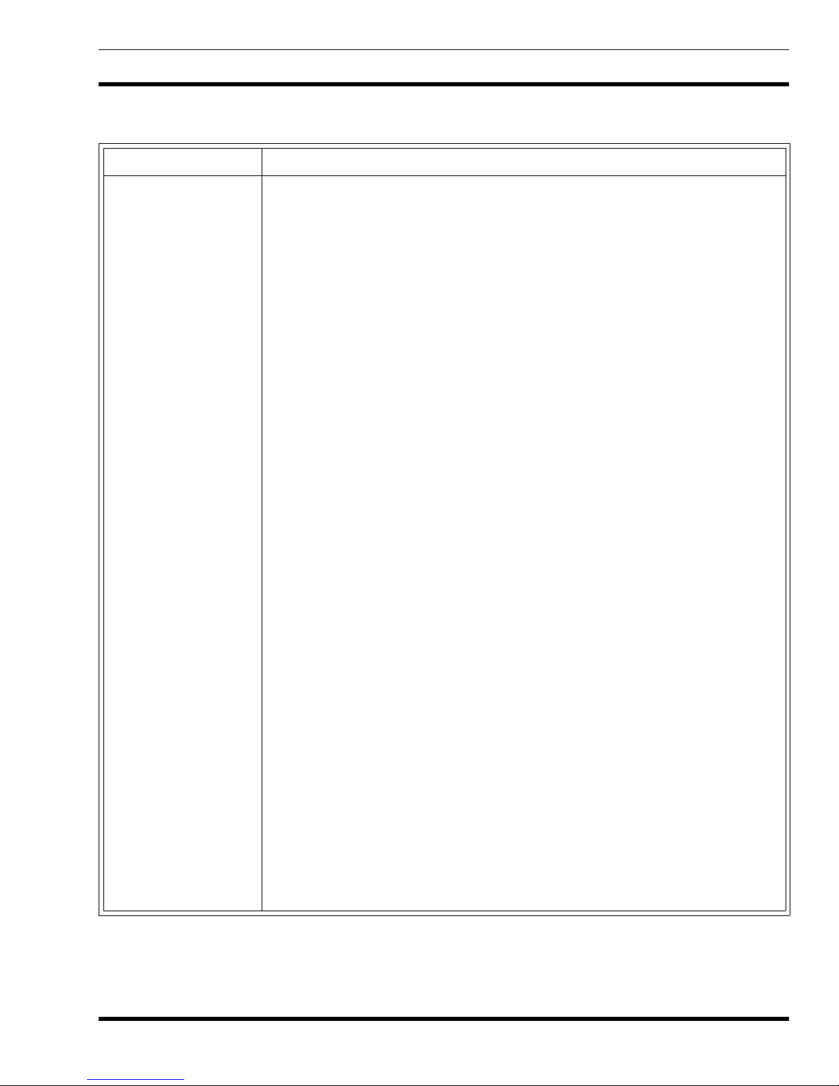
SYMPTOMS AND CHECKS
SYMPTOMS CHECKS
Handset Blank On PowerUpRefer to the Power Distribution Block Diagram. Check for filter ed A+ to the han dset at J701-3,
8 volts at J702-6 o r switched A+ at J905-5 (system board).
Radio Will Not Go Into
Test Mode Operation
Low, Distorted, or No RX
Audio
No RX Alert Tone Check the signalling tone output from the Logic Board. Operate the volume control. If tones
Poor RX Sensitivity Simplex operations: Suspect the RF Board. Check receiver alignme nt. Refer to the RF Board
No TX Power Check the DPTT command to the RF Board. If present, then the problem is likely on the RF
Low TX Power Check the transmit frequency. If its not OK, check the synthesizer on the RF Board and the
The radio m ust b e P C programm ed to enable the test mode. Enable it on the options screen.
Check th e receiver VOL/SQ HI o utput. If distorted, t he proble m is m ost likel y on the RF Board .
If synthesizer lo ad com ma nds a r e not cor rect , the proble m ma y b e on the Logic B oa rd .
If the audio is correct at VOL/SQ HI, check the RX audio out. If improper, check the Audio
Board for pr oper unmute com mands from the Logic Board. Proper commands i ndicate a fau lty
Audio Board.
are not present, the Logic board may be faulty.
maintenance manual.
Duplex Operation: If receiver OK, check lead placement on Duplexer/Talk-Around Board.
Board. If the DPTT is not presen t, th e proble m is likel y on the Logic Bo ard.
synthesizer lo ad comm ands f rom t he L ogic Bo ard. If t he comma nds a re n ot prese nt, a problem
on the Logic Board is likely.
If the TX frequency is correct, refer to the maintenance manual for the RF Board and
troubleshoot the transmitter.
No TX Modulation Check the TX MOD input to the RF Board. If present, the RF Board may be faulty. If not
present, dete r mine w h at is missing: tone, voice , or both .
Missing tones - L ook for the s ignal ling to ne and busy to ne o n th e Au dio Boa rd. If the to nes a re
not presen t, the Logic Board m ay be faulty.
Tones present - look for the proper unmute commands on the Audio Board from the Logic
Board. If the commands are not present, the Logic Boa rd may be faulty. If the commands ar e
present, the Audio Board may be faulty.
Missing Voice Signal - Check the mute comm ands on the Logic Board and th e TX Audio input
to the Audio Board. If all signals are correct, the problem is likely a faulty Audio Board. If no
signal is present at the Audio Board, check the output from the Audio Amplifier board and
handset outputs.
Radio Will Not Program
When Plugged Into The
TQ3310 or TQ3370
Interface Module
The radio must b e tur ne d "on" b efore programming. Connec t the handset and press the on/o f f
power switch.
7
 Loading...