

Page 1

Operator’s Manual
LBI-38795B
AEGIS
ED ACS
®
M-PA
SYSTEM MODEL
PORTABLE RADIO
E
Page 2

Table of Contents
Table of Contents (Cont.)
INTRODUCTION . . . . . . . . . . . . 5
CONTROLS . . . . . . . . . . . . . . 5
INDICATORS . . . . . . . . . . . . . . 10
OPERATION . . . . . . . . . . . . . . 13
POWER-UP . . . . . . . . . . . . . 13
SYSTEM/GROUP/CHANNEL
SELECTION . . . . . . . . . . . . . 14
VOICE MODES . . . . . . . . . . . 15
Clear Modes . . . . . . . . . . . 15
This manual is published by
without any warranty. Improvements and changes
to this manual necessitated by typographical errors, inaccuracies of current information, or improvements to programs and/or equi pment, may be
made by
notice. Such changes will be incorportated into new
editions of this manual. No part of this manual may
be reproduced or transmitted in any form or by an y
means, electronic or mechanical, including photocopying and recording, f or any purpose, without the
express written permission of
Copyright © M ay 1992, Ericsson GE M obile Communicat i ons Inc.
Ericsson Inc.
, at any time and without
Ericsson Inc.
Ericsson Inc.
Aegis Digital Mode . . . . . . . 16
Aegis Private And Voice Guard
Private Modes . . . . . . . . . . 16
TRUNKED MODE OPERATION . . . 20
Receiving A Message . . . . . . 20
Sending A Message . . . . . . 21
Emergency Operation (Trunked
Mode) . . . . . . . . . . . . . . 23
Dynamic Regrouping . . . . . . 23
Wide Area System Scanning . . 24
Scanning Trunked Groups . . . . 24
,
Special Calls . . . . . . . . . . 26
Manually Dialed Telephone Inter-
connect Calls . . . . . . . . . . . . 29
STATUS MESSAGE OPERATION . . 30
CONVENTIONAL MODE
OPERAT ION . . . . . . . . . . . . 30
Receiving A Message . . . . . . 30
Sending A Message . . . . . . 31
Emergency Operation (Conven-
tional Mode) . . . . . . . . . . . 33
Scanning Conventional
Channels . . . . . . . . . . . . 33
2
Page 3

Table of Contents (Cont.)
PRODUCT SPECIFICATION FOR CE
MARKED EQUIPMENT
OPERAT ING TIPS . . . . . . . . . . . 34
OPERATING RULES AND REGULA-
TIONS . . . . . . . . . . . . . . . . . 35
BATTERY PACKS . . . . . . . . . . . 36
INSTALLING THE BATTERY PACK . 36
REMOVING THE BATTERY PACK . . 36
CHARGING THE BATTERY PACK . S38
RECHARGEABLE BATTERY PACK
DISPOSAL . . . . . . . . . . . . . . 38
SWIVEL MOUNT REMOVAL AND
REPLACEMENT . . . . . . . . . . . . 38
GLOSSARY . . . . . . . . . . . . . . 39
WARRANTY . . . . . . . . . . . . . . 44
NICKEL-CADMIUM BATTERY
WARRANTY . . . . . . . . . . . . . . 45
The M-PA Portable conforms to the following
Product Specifications.
EUROPEAN STANDARDS:
Safety: Not applicable
EMC: prETS 300 279 (August 1995)
TTD: Not applicable
SUPPLEMENTARY INFORMATION
At this time, the M-PA portable radio may not
be operated while in a vehicular charger in the
European Community since it has not been evaluated for operation in this mode.
The M-PA portable radio ma y be used in both
trunked and conventional applications.
3
Page 4
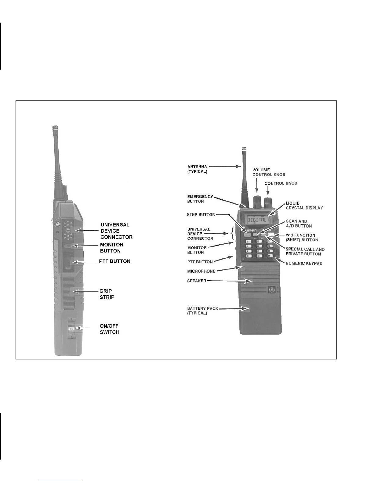
SIDE VIEW
FRONT VIEW
Figure 1 - Aegis EDACS M-PA System Model Radio
4
Page 5

INTRODUCTION
The Aegis
ED AC S M-PA System model
portable radio is a high-performance two-way radio that provides clear voice, Aegis digital, and
Aegis private communications. The radio is also
®
compatible with Voice Guard
communication
systems. Personality programming allows maximum integration flexibility into EDACS and conventional radio systems.
The radio must be equipped with the encrypt/decrypt option before operation in Aegis
private or Voice Guard modes is possible. This
option allows the radio to communicate using
highly secure state-of-the-art Aegis and Voice
Guard encryption and decryption techniques.
Operating controls on the radio include a
rotatable system/group/channel control knob, rotatable volume control, 16-button keypad, pushto-talk, emergency and monitor buttons. The
on/off power switch for the unit is located on the
removable battery pack.
The 8-digit alphanumeric liquid crystal display
(LCD) on the front of the radio displays the oper-
ating status of the radio. This backlit display also
has sixteen status flags that indicate various operating conditions such as private communications enabled, transmitter on, scanning, or
emergency mode enabled.
The exact operation of your radio will vary
depending upon the mode of operation, the radio’s programming, and the par ticular radio system. Consult your radio system’s representative
for particular features that are programmed into
your radio.
CONTROLS
ON/OFF SWITCH
The ON/OFF SWITCH is located on the battery pack. Sliding this s witch up will supply power
to the radio from the battery pack. An audible click
will be heard and the "ON" indicator will be exposed. When the radio is turned on, it will perform
a power-up self test and then resume operation
on the previous operating system, group or channel as displayed in the LCD. Sliding the switch
down will turn the radio off.
5
Page 6

VOLUME CONTROL KNOB
PTT BUTTON
The VOLUME CONTROL KNOB is a rotatable
control on the top of the radio used to adjust the
receiver’ s audio le v el in the speaker . Rotating this
knob in a clockwise direction will increase the
audio level. Counter-clockwise rotation will decrease the audio level. Minimum levels may be
programmed into the radio to pre vent missed calls
due to too low of a volume setting.
CONTROL KNOB
The rotatable 16-position CONTROL KNOB
located on the top of the radio may be programmed to select trunked groups and conventional channels or it may be progr ammed to select
systems. See SYSTEM/GROUP/CHANNEL SE-
LECTION for details.
A stop plate may be installed under the knob
to limit the maximum number of positions to less
than sixteen (16). It is nor mally factory installed
for fifteen (15) positions.
Pressing the PTT BUTT ON on the side of the
radio will enable the radio’s transmitter. The "TX"
status flag in the display will turn on when the radio
is transmitting. Releasing the PTT BUTTON will
return operation to receive mode.
When operating in a trunked system, the radio
may be programmed to automatically transmit
(without the operator pressing the PTT BUTTON)
to maintain communication with the site contr oller.
The "TX" status flag will turn on when the radio is
transmitting.
MONITOR BUTTON
Trunked Mode
When operating in trunked mode, pressing
the MONITOR BUTTON after an individual call
has been received will return the radio to the
group call mode. The r adio will not respond on an
individual basis, but will then transmit group calls
when the PTT BUTT ON is pressed. The radio will
also automatically return to the group call mode
after the programmed call-back time-out period
expi res.
6
Page 7

Pressing the MONITOR BUTTON will also
clear any digits entered from the numeric keypad
and return the radio to the selected group displa y.
In addition, this button is used to toggle between group and regroup settings if the Dynamic
Regrouping mode (with deselect capability) has
been enabled by the site controller.
Conventional Mode
When the radio is operating in conventional
mode the MONITOR BUTTON is used to unsquelch the receiver. If programmed for the selected channel, it will also toggle Channel Guard
(CG) and/or Type 99 (T99) signaling on and off.
Momentarily pressing the MONITOR BUTTON will unsquelch the receiver. If programmed,
pressing and holding the button for at least one
(1) second will toggle CG and/or T 99 signaling on
or off. After a T99 call has been received, pr essing
the MONITOR BUTT ON will reset the radio f or the
next call. Note: Selecting another channel will
turn CG and T99 signaling back on if programmed
for the channel.
EMERGENCY BUTTON
When operating in trunked mode, pressing
and holding the red EMERGENCY BUTTON on
top of the radio for approximately one (1) second
will initiate an emergency call with voice operation
on the programmed home group. If no home
group is programmed into the radio, voice operation will be on the selected group.
In conventional mode, initiating an emergency call by pressing the EMERGENCY BUTTON will cause the radio to transmit GE-STAR
signaling on the programmed emergency channel. If no emergency channel is programmed,
GE-STAR will be transmitted on the selected
channel.
STEP BUTTON
The STEP button located on the keypad may
be programmed to select trunked groups and
conventional channels or it may be programmed
to select systems. See SYSTEM/GROUP/CHAN-
NEL SELECTION for details.
7
Page 8
STEP is also used to scroll through the programmed special call table when the special call
mode is enabled.
SCAN BUTTON
Pressing the SCAN button on the keypad will
toggle scan operation on and off . When the radio
is scanning, the "SCN" status flag in the display
will show and all groups/channels on the scan list
in the current system will be scanned.
SPECIAL CALL BUTTON
When operating in trunked mode, pressing
SPC will switch operation from the group select
mode to the special call mode. The last selected
special call will be displayed.
While in special call mode, the next programmed special call may be selected by pressing STEP. Pressing 2nd then STEP will select the
previous progr ammed special call. The caller’s ID
of the last received individual call and the last
received group call on the selected g roup are also
selectable using this method. See
Special Calls
for details.
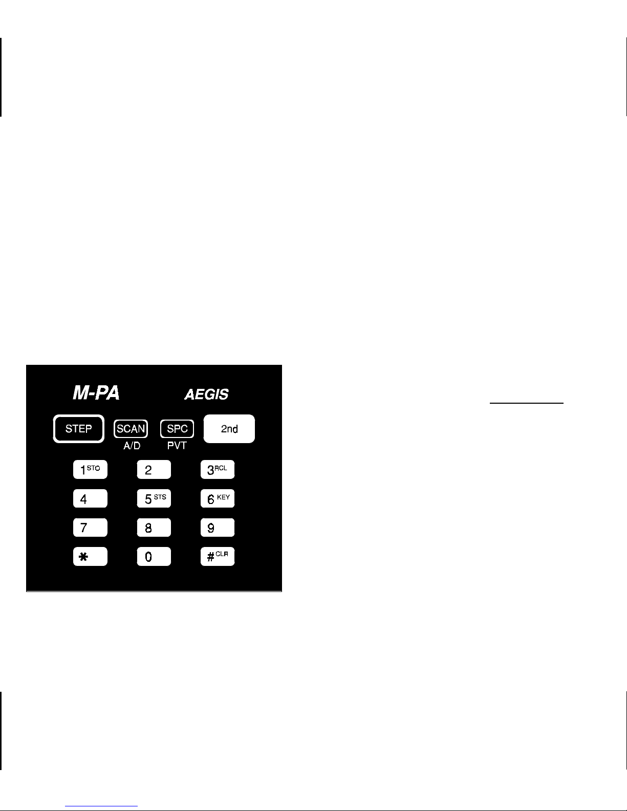
2nd FUNCTION BUTTON
Seven (7) of the buttons on the keypad are
dual-function buttons. Press and release the blue
2nd function button to shift keypad selection to the
A/D, PVT, STO, RCL, CLR, KEY or STS buttons.
The following paragraphs describe operation of
the shifted buttons.
Figure 2 - Keypad
8
Page 9

ADD/DELETE BUTTON (Shifted SCAN
Button)
PVT (shifted SPC button). When enabled, the
"PVT" status flag in the display will turn on.
When in trunked mode, pressing and releasing 2nd and then pressing A/D (shifted SCAN
button) will add the selected group to the scan list
if it is not already on the list. Repeating this
sequence will delete the group from the list. When
the selected group is on the scan list, the "S"
status flag will show in the display.
In conventional mode, pressing and r eleasing
2nd and then pressing A/D will scr oll the selected
channel’ s scan priority between non-priority scan
("S" status flag), priority-two scan ("2" status flag),
priority-one scan ("1" status flag) and no scan (no
status flags).
Scan must be turned off before groups or
channels can be added to or deleted from the
scan list. See SCAN BUTTON for details.
PRIVATE BUTTON (Shifted SPC Button)
Private transmit mode is enabled or disabled
by pressing and releasing 2nd and then pressing
If the radio is programmed for forced private
operation, "FRCD PVT" will be displayed when
2nd-PVT is pressed; private transmit mode is not
disabled. If the selected group or channel is not
programmed f or priv ate operation, "P VT DIS" will
momentarily show in the display when 2nd-PVT
is pressed; the radio will not change to private
mode. See PRIVATE COMMUNICATIONS for
additional details.
STORE BUTTON (Shifted Digit 1)
STO (shifted digit 1) allows ten (10) telephone
numbers and ten (10) radio ID numbers to be
stored and later recalled with the RCL button.
Store a telephone number by entering the
number (up to 29 digits) followed by an asterisk
(*). Next, enter the storage location (1-10) and
press and release 2nd and then press STO.
"STORED" will be displayed for two seconds.
Store individual radio ID numbers b y entering
the ID number (1 - 16382) followed by a pound
9
Page 10

sign (#). Next enter the storage location (1-10) and
press and release 2nd and then press STO.
"STORED" will be displayed for two seconds.
RECALL BUTTON (Shifted Digit 3)
RCL allows the previously stored telephone
or radio ID numbers to be recalled. To recall a
number first enter an * or # (* for telephone
number , # f or radio ID number) and then enter the
storage location (1-10). Next press and release
2nd and then press RCL and the number will be
displayed.
CLEAR BUTTON (Shifted # Button)
To clear the last digit entered, press and release 2nd and then press CLR (shifted # button).
Holding CLR down will repetitively clear previous
digits. The radio will return to the last operating
state when all entered digits are cleared.
KEY BUTTON (Shifted Digit 6)
Pressing and releasing 2nd and then pressing
KEY (shifted digit 6) will display the current oper-
ating cryptographic number . See PRIVATE COM-
MUNICATIONS for details.
STATUS BUTTON
The STS button will be used for future status
operations.
KEYPAD LO CK FEATURE
To prev ent accidental activation of the buttons
on the keypad, simultaneously press SCAN and
SPC to lock the keypad; "LOCKED" will be displayed momentarily. To unlock the keypad, press
SCAN and SPC a second time; "UNLOCKED" will
be displayed momentarily.
INDICATORS
The radio’s liquid crystal display (LCD) located on the front panel has eight (8) alphanumeric characters and sixteen (16) status flags.
This display provides indications of the current
operating system, group or channel and it displays v arious other messages such as special call
ID names or numbers, and telephone interconnect numbers.
10
Page 11

LCD backlighting will turn on f or a short period
anytime an active button is pressed or the CONTROL KNOB is rotated. Backlighting may be
programmed to remain off at all times.
HI HIgh power transmit - On indicates
the selected system or channel has
been programmed for high power
transmit operation. Off indicates low
power transmit.
The sixteen (16) status flags located along the
top and bottom of the display indicate operating
modes and conditions as follows:
Figure 3 - Liquid Crystal Display
EMG EMerGency mode - On indicates an
emergency call has been initiated by
the user. Flashing indicates an emergency call has been received.
NC No Control channel - On indicates the
radio is not receiving the trunked control channel. Flashing indicates the
trunked system is in a failsoft condition
(supervisory radios only).
MSG MeSsaGe - Flashing indicates an in-
dividual call has been received
(trunked mode).
T99 Type 99 tone decode - On indicates
Type 99 tone decoding is enabled on
the selected conventional channel.
Flashing indicates a T99 selective call
has been received and the radio must
be reset to receive another T99 call.
CNV CoNVentional mode - On indicates the
radio is operating in the conventional
mode.
SPC SPecial Call mode - On indicates the
special call mode has been enabled
(trunked mode).
PVT PriVaTe mode - On indicates private
mode is enabled and the radio will
transmit encrypted messages on the
selected group or channel. Flashing
indicates an encrypted message is being received.
11
Page 12

TX Transmitter enabled - On when the
radio is transmitting.
BSY BuSY - When in trunked mode, on
indicates the radio is receiving a call;
flashing indicates a call has been
queued. In conventional mode, on indicates a carrier is being received.
CG Channel Guard - On indicates Chan-
nel Guard encode/decode is enabled
on the selected conventional channel.
BAT BATtery low - On indicates the batter y
pack’s charge is low.
UNIVERSAL DEVICE CONNECTOR
The Universal Device Connector (UDC) is
located on the side of the radio just above the PTT
and MONITOR BUTTONS. This connector provides connections for the external accessories
such as a headset, a speaker-mike, or an emergency lanyard. When the radio is locked in a
vehicular charger/repeater the UDC provides the
audio and control connections between the radio
and the vehicular charger/repeater. The UDC is
also used by the maintenance personnel when
the radio is programmed.
S Scan list - On indicates the selected
group/channel is on the scan list.
1 priority 1 - On indicates the selected
conventional channel is designated as
the priority-one scan channel.
2 priority 2 - On indicates the selected
conventional channel is designated as
the priority-two scan channel.
SCN SCaN mode - On indicates the radio is
scanning.
12
ALERT TONES
The radio soun ds five (5) basic al ert tone s or
"beeps" to in dicate various operatin g conditions.
Aler t tones may be programmed to remain of f at
all times.
•
500 Hz Tone
–
trunked failure tone sounds when a trunked
failure has occurred (call
denied, failed confirmation).
–
low battery - sounds when
the battery pack’s charge
is low.
Page 13

•
‘800 Hz Tone
•
1000 Hz Tone
•
1200 Hz Tone
–
private mode disabled on a conventional channel, sounds when the PTT
BUTTON is pressed if private transmit mode has
previously been disabled.
–
alert tone - sounds when
a button is pressed and a
status change occurs
–
channel access tone sounds when a trunked
channel has been assigned and it is clear to
talk.
–
private mode channel access tone - sounds when
the radio is in the private
transmit mode, a trunked
channel has been assigned and it is clear to
talk.
OPERATION
POWER-UP
After the battery pack and antenna ha ve been
installed, turn the radio on by sliding the ON/OFF
SWITCH on the battery pack up. After the radio
has completed a power-up self-test, it will begin
operation on the last operating state as displayed
in the LCD . If programmed on, the power -up alert
tone (beep) will be heard.
If the radio was previously operating in a
trunking system and communication with this system’s control channel cannot be established, the
"NC" status flag will turn on. This ma y occur if, for
example , the radio is out of range of the previous
trunking site. It may be necessar y move to another location, select another trunking system, or
a conventional channel.
•
2500 Hz Tone
–
call queued tone - sounds
when a trunked call is
queued.
13
Page 14

SYSTEM/GROUP/CHANNEL SELECTION
The radio may be programmed with one of
two different system/group/ channel selection
modes as follows:
•
Systems are selected with the STEP but-
ton; groups and channels are selected with
the CONTROL KNOB.
or
•
Systems are selected with the CONTROL
KNOB; groups and channels are selected
with the STEP button.
down STEP will cause the radio to automatically
scroll through the system list.
Upon reaching an end of the system list, the
radio may be programmed to stop selection or
wrap around (go from one end to the other).
Systems may also be selected by entering the
system number from the numeric keypad and
then pressing STEP. If a number out of the programmed range is entered, "RANGE" will be displayed.
Group/Channel Selection
STEP Button Programmed For System
Selection
CONTROL KNOB Programmed For
Group/Channel Selection
System Selection
Press and release STEP to select the next
system programmed into the r adio as indicated in
the display. To select the previous system, press
and release 2nd and then press STEP. Holding
14
After the desired system is selected with the
STEP button, rotate the CONTROL KNOB to the
desired trunked group or con ventional channel as
indicated in the display. A stop-plate may be
placed under the knob which will limit the maximum positions to less than sixteen (16).
CONTROL KNOB Programmed For System
Selection
STEP Button Programmed For
Group/Channel Selection
Page 15

System Selection
VOICE MODES
Rotate the CONTROL KNOB to the desired
system as indicated in the display. A stop-plate
may be placed under the knob which will limit the
maximum positions to less than sixteen (16).
Group/Channel Selection
After the desired system is selected with the
CONTROL KNOB, press and release STEP to
select the next trunked group or conventional
channel programmed into the radio as indicated
in the display. To select the previous group or
channel, press and release 2nd and then press
STEP. Holding down STEP will cause the radio to
automatically scroll through the group/channel
list.
Upon reaching an end of the group/channel
list, the radio may be programmed to stop selection or wrap around (go from one end to the other).
Groups or channels may also be selected by
entering the group/channel number from the numeric keypad and then pressing STE P. If a number
out of the programmed range is entered,
"RANGE" will be displayed.
Each system (trunked or conventional) in the
radio is programmed for either Aegis or Voice
Guard communications. Aegis programmed systems have three (3) different voice modes: clear,
digital and private. Voice Guard systems hav e two
(2) voice modes: clear and private. The voice
modes are programmed on a per-group basis
within each trunked system and on a per-channel
basis within each conventional system. A radio
must be equipped with the encrypt/decrypt option
before it will operate in Aegis private or Voice
Guard modes.
Clear Modes
Aegis clear and Voice Guard clear modes are
identical voice modes in which the radio tr ansmits
and receives only clear (analog) voice signals.
These analog signals are non-digitized and nonencrypted. Clear m ode transmissions can be easily monitored by unauthorized persons. Groups
and channels programmed for clear operation
cannot transmit or receive Aegis digital or private
messages.
15
Page 16

TRANSMIT/RECEIVE MODE COMPATIBILITY
FOR AEGIS OPERATION
GROUP/CHANNEL
PROGRAMMING
(TRANSMIT)
CLEAR Yes No No
DIGITAL Yes Yes No
PRIVATE Yes No Yes *
RECEIVE CAPABILITY
CLEAR DIGITAL PRIVATE
TRANSMIT/RECEIVE MODE COMPATIBILITY
FOR VOICE GUARD OPERATION
Aegis Digital Mode
Aegis digital mode allows the radio to transmit
and receive digitized voice signals. Aegis digital
signals provide improved weak signal performance and they cannot be easily monitored with a
standard receiver. Groups and channels programmed f or Aegis digital operation tr ansmit only
digital signals and they can receive clear and
digital signals. In other words , with a certain group
or channel selected, the operator cannot change
from the digital transmit mode but the radio will
receive clear or digital signals. Private (encrypted)
messages cannot be received when the radio is
in Aegis digital mode.
Aegis Private And Voice Guard Private
Modes (Optional)
GROUP/CHANNEL
PROGRAMMING
(TRANSMIT)
CLEAR Yes No
PRIVATE Yes Yes *
RECEIVE CAPABILITY
CLEAR PRIVATE
* assumes the proper cryptographic key is loaded
16
The Aegis private and Voice Guard private
modes allow the radio to transmit and receive
encrypted messages. To operate in these voice
modes, the radio must be equipped with the optional encrypt/decrypt feature and the transm itting
and receiving units must have identical cryptographic keys.
Page 17

Aegis transmissions cannot be received by a
radio set to receive a Voice Guard transmission.
Accordingly, a Voice Guard transmission cannot
be received by a radio set to receive an Aegis
transmission.
Cryptographic keys are transferred into the
radio using a cryptographic Keyloader. Up to
sev en (7) diff erent cryptographic ke ys, number ed
1 - 7, can be transferred from a Keyloader and
stored in the radio. An individual key is automatically selected on a per-group/channel basis according to the radio’s programming. Groups and
channels within Aegis systems can be programmed for keys 1 - 6. Groups and channels
within Voice Guard systems can be programmed
for keys 1 - 7.
clear and private signals . The "PVT" status flag in
the display turns on when the private mode is
enabled. If the selected group or channel is programmed for autoselect capability, the mode may
be toggled between private and clear using the
2nd - PVT buttons (shifted SPC). Radios programmed for forced private operation do not allow
a change of the transmit mode; the PVT button
does not function.
Transferring Keys Into The Radio
NOTE
Before private messages can be sent or
received, one or more cryptographic
keys must be transferred into the radio
from the Keyloader.
DES radios require a DES Keyloader (option
V4025). Operating details on the DES Keyloader
are contained in LBI-31541. V GE radios require a
VGE K eyloader (option V4028). See LBI-31685 for
operating details on the VGE Keyloader.
When operating on a group or channel programmed for private mode, all transmissions will
be private transmissions and the radio will r eceive
The following procedure outlines basic key
transferring steps.
1. Turn the radio off.
2. Plug the modular connector of the Key-
loader cable into the Keyloader’s modular jack.
17
Page 18

3. Connect the Ke yloader cable to the UDC
on the radio.
4. Press the PWR button on the Ke yloader
and wait for the Keyloader to display
"MASTER MODE".
5. Press the TRN button on the Keyloader.
If necessary, select a different cryptographic key to be transferred into the
radio.
Key Zero
All cryptographic keys can be zeroed or
"dumped" when the radio is on by simultaneously
pressing the STEP and 2nd buttons for at least
one second. When the ke y(s) ha v e been zer oed,
the radio will display "KEY ZERO" and it will emit
a series of beeps. If the cryptographic ke y( s) ar e
zeroed, one or more k eys must be transf erred into
the radio from the Keyloader before private communications may continue.
6. Tur n the radio on. The display should
read "KEY LOAD".
7. Press the EXE button on the Keyloader
to transfer the key. The Keyloader will
display "GOOD 1.x TRANSFER" where
"x" is the selected cryptographic key
number.
8. Disconnect the cable from the radio’s
UDC. A single beep will be heard from
the radio’s speaker if the power-up alert
tone is enabled. The radio will change to
the selected group or channel as indicated in the display.
18
In addition, removing the battery pack for
sev eral minutes (typically thr ee) or disassemb ling
the front half of the radio from the rear half will also
zero all ke ys. The radio does not have to be turned
on to zero the key(s) using either of these procedures (DES versions only).
Displaying The Cur rently Used
Cryptographic Key Number
To display the cr yptographic key currently in
use, press and release 2nd and then press KEY
(shifted 6). One of the following messages will be
display ed:
Page 19

• "KEY x" - where "x" is the key number (1
- 7) currently in use.
Transmitting An Encrypted Message
• "NO KEY x" - where "x" is the key number
(1 - 7) program med for the selected group
or channel. The selected group or channel
has been programmed for private operation but the ke y has been zer oed or ne v er
transferred into the radio. This message
will periodically show in the display under
this condition.
• "PVT DIS" - the selected group or channel
is not programmed for private operation.
Receiving An Encrypted Message
When receiving, the radio automatically
switches between clear or private operation. If the
transmission being received is an encrypted
transmission, it will be decrypted, the "PVT" status
flag will flash, the receiver will unsquelch, and the
message will be heard in the speaker . For this to
occur, the selected group or channel must be
programmed f or private operation and the corr ect
cryptographic key must be loaded into the radio.
1. Select the desired group or channel.
2. Toggle operation to private transmit by
pressing and releasing 2nd and then
pressing PVT (shifted SPC button).
When private transmit mode is enabled,
the "PVT" status flag in the display will
turn on.
If a group or channel is not progr ammed
for private mode operation, "PVT DIS"
will momentarily show in the displa y if an
attempt is made to enable private transmit mode. It is not possible to oper ate on
this group/channel in private mode.
If the radio is programmed for forced
private transmit operation, "FRCD PVT"
will momentarily show in the displa y if an
attempt is made to disable private transmit mode. It is not possible to transmit
on this group/channel in clear mode.
3. Continue with standard transmission
procedures. In conventional mode, if a
19
Page 20

channel is programmed for private operation and private transmit mode has
been disabled, the radio will sound an
alert tone when the PTT BUTTON is
pressed to warn of the clear (non-encrypted) transmit mode.
TRUNKED MODE OPERATION
Digital trunking provides fast communication
access. In this mode the operator selects a communication system and group and the communication channel is allocated through digital
signaling with the site. The following operation is
applicable to clear, digital and private operation
unless otherwise noted.
Receiving A Message
1. Slide the ON/OFF SWITCH on the bat-
tery pack to the on position. The radio
will initiate and complete the power-up
self-test then the system’s name and
"NC" status flag will be displayed until a
control channel is located. When the
control channel is located, the "NC"
status flag disappears and the group
name is displayed.
2. Adjust the VOLUME CONTROL to an
approximate mid-range position.
3. Select the desired system and group
using the STEP button and CONTROL
KNOB. See the SYSTEM/GROUP/-
CHANNEL SELECTION operating procedures for details. The display
indicates the selected group.
4. The radio is now ready to receive mes-
sages.
5. GROUP CALL - When a group call is
received, the radio unsquelches on the
assigned channel and the "BSY" status
flag turns on. The group name or the
originator’s ID (depending on programming) is display ed. Adjust the v olume as
necessary .
INDIVIDU AL CALL - If an individual call
(a call directed to only one radio) is received, the radio will unsquelch on the
assigned channel and the "BSY" status
flag will turn on. "*INDV*", originators ID ,
or the caller’s name (if programmed) is
20
Page 21

displayed and the "MSG" status flag
flashes. Adjust the volume as necessary.
Responding to an individual call prior to
the programmed call-back time-out will
automatically direct the transmission to
the originating unit on an individual basis.
The "MSG" status flag will remain flashing ev en after the individual call time-out
period expires. Press the SPC button
(SPecial Call) to call the originating unit
back. The originator’ s ID or name will be
displayed. Follow the procedures for
sending a special call.
switches between clear or private operation when it is receiving on a group or
channel programmed for private operation.
Sending A Message
1. Tur n the radio on, set the receive audio
level and select the desired system and
group.
2. When private transmit mode is enabled,
the "PVT" status flag in the display will
turn on. Toggle transmit operation to
private or clear, as desired, by pressing
and releasing 2nd and then pressing
PVT (shifted SPC button).
ENCRYPTED MESSAGE - If the transmission being received is an encrypted
transmission
programmed for private operation
and the selected group is
and
the correct cryptographic key is loaded
into the radio, then the receiver will unsquelch, the "PVT" status flag will flash
and the private message will be heard in
the speaker. The radio automatically
3. Observe the display for the absence of
the "BSY" status flag to ensure no one is
transmitting on the selected group.
4. Press and hold the PTT BUTTON. The
radio will perform the necessary signaling required to obtain a communication
channel.
21
Page 22

5. When the channel has been acquired,
the "TX" and "BSY" status flags are displayed and the channel access alert
tone (one beep) is heard.
6. Hold the radio approximately three
inches from your mouth and speak into
the microphone in a normal voice.
NOTES
If a group is not programmed for private mode operation, "PVT DIS" will
momentarily show in the display if
an attempt is made to enable private
transmit mode. It is not possible to
operate on this group in private mode
7. Release the PTT BUTTON when the
transmission is complete. If the transmission exceeds the programmed Carrier Control Timer limit, the radio will
unkey and an alert tone will sound.
8. Listen for a reply.
If the radio is programmed for forced
private operation, "FRCD PVT" will
momentarily show in the display if
an attempt is made to disable private
transmit mode. It is not possible to
transmit on this group in clear mode.
If a group programmed for private operation has been selected and there is
no key in the radio for the selected
group, "NO KEY x" (where "x" is the
key number) will periodically flash in
the display. If a transmission is attempted, "NO KEY x" will show in the
display and the radio will emit a series
of beeps and will not transmit.
22
Page 23

Emergency Operation (Trunked Mode)
Receiving An Emergency Call
3. Release the PTT BUTTON when the
transmission is complete and listen for a
reply.
If the radio receives an Emergency Channel
Assignment in trunked mode, an alert tone
sounds and the "EMG" status flag starts flashing.
Follow standard emergency procedures.
Sending An Emergency Call
1. To enable an emergency transmission,
press and hold the EMERGENCY BUTTON (small red b utton near antenna) f or
approximately one second. The radio
transmits an emergency message until
an Emergency Channel Assignment is
received. Upon receipt, the "EMG"
status flag turns on and the radio begins
operation on the selected group or the
home group, depending upon programming.
2. Press the PTT BUTTON and speak into
the microphone in a normal voice.
Clearing An Emergency
If programmed for supervisory capabilities,
the M-PA can clear an emergency declared by it
or another radio. To clear an emergency on the
selected talk group, pr ess "2nd", then "CLR" then
press the red EMERGENCY BUTTON near the
antenna. The M-PA will then send a clear emergency message, lighting the "TX" flag. The "BSY "
status flag will come on briefly after the "EMG"
status flag goes out.
Dynamic Regrouping
Dynamic Regrouping is a feature which allows the System Manager to dynamically program
new groups into selected radios. Upon development of the regrouping plan, the site controller
sends each radio the regroup plan number, knob
setting(s), and activate/deactivate commands.
23
Page 24

When the radio is regrouped, it will alert the
user and the display will indicate "REGRP nn" (nn
= 01 - 08 depending upon the CONTROL KNOB
setting).
TON a second time will return operation
to the regroup mode and private or clear
mode as the radio was pre viously operating.
If the regroup plan has deselect capability
active on the selected system, press the MONITOR BUTTON to toggle between the group and
regroup modes.
Private mode Dynamic Regrouping operates
as follows:
• When the radio is regrouped, all regroups
will initially operate in clear mode.
• When regrouped, the operator may toggle between private and clear mode by
pressing 2nd-PVT. There is no forced
private regroup mode.
• Regroup operation always uses cryptographic key 1.
• If the radio is programmed for deselect
capability, pressing the MONITOR BUTTON will return operation to the programmed groups in the radio, and to private or clear mode as the radio is programmed. Pressing the MONITOR BUT-
Wide Area System Scanning
M-PA radios may be programmed for wide
area system scan operation for m ulti-site applications. Upon the loss of the currently selected
system’s control channel, radios may be programmed to automatically scan the control channels of up to six other systems. If a new control
channel is found, the radio will switch to the new
system and sound an alert tone. Group selection
may change upon switching to the new system.
The radio may also be progr am med for priority wide area system scan. A priority system may
be assigned to each system programmed into the
radio. Radios programmed in this manner will
scan the priority trunked system’ s control channel
once ever y one, two, three or four minutes (programmable). This priority scan timer is reset each
time the PTT BUTTON is pressed.
24
Page 25

Scanning Trunked Groups
Groups which hav e been pre viously added to
the scan list on a per system basis may be
scanned. Each system’s scan list is retained in
memory when the radio is turned off or when the
battery pack is removed.
The radio will not scan when the emergency
mode is enabled ("EMG" status flag is on).
status flag will be on if the group is
presently on the scan list.
3. Toggle the "S" status flag on or off, as
desired, by pressing 2nd and then A/D
(shifted SCAN button). When the "S"
status flag is on, the group is on the scan
list. When the "S" status flag is off, the
group has been deleted from the list and
will not be scanned.
The following procedures outline scan operations for trunked groups. See the conventional
mode operating procedures for specific procedures on conventional channel scanning.
Adding Groups To And Deleting Groups
From The Scan List
1. Scan must be off to add groups to and
delete groups from the scan list. The
"SCN" status flag will be on if scan is on.
If necessary , toggle scan operation off by
pressing SCAN.
2. Select the desired group to be added to
or deleted from the scan list. The "S"
Using Scan
1. Toggle scan operation on by pressing
SCAN. The "SCN" status flag will turn on
when the radio is scanning.
2. When a group on the scan list receives
a channel assignment, the radio unsquelches on the assigned channel and
the group name is displayed.
The radio will continue scanning if a new
group is selected when scan is on.
25
Page 26

Pressing the PTT BUTTON when scan
is on will cause the radio to transmit on
the selected group.
A "nuisance" group can be deleted from
the scan list by pressing 2nd-A/D while
the radio is receiving the "nuisance" call.
The group will be deleted from the scan
list. Add the group back to the scan list
by turning the radio off and back on or by
turning scan off, selecting the group, and
pressing 2nd-A/D.
3. Toggle scan operation off by pressing
SCAN. The radio will resume operation
on the selected group.
the assigned channel and the "BSY" status flag
will turn on. "*INDV*", originators ID , or the caller’ s
name (if programmed) is displa yed and the "MSG"
status flag flashes. Adjust the volume as necessary.
Responding to an individual call prior to the
programmed call-back time-out will automatically
direct the transmission to the originating unit.
Follow the instructions for sending a special call.
If the call is not answered, the "MSG" status
flag will remain flashing even after the individual
call time-out period expires. Press SPC (SPecial
Call) to call the originating unit back. The originator’s ID or name will be displayed.
Special Calls
Special calls include individual and telephone
interconnect calls. Up to 99 different special calls
can be programmed into the radio and selected
for transmission.
Receiving An Individual Call
When an individual call (a call directed to only
one radio) is received, the r adio will unsquelch on
26
Sending A Special Call
Use the following procedure to send one of
the special calls programmed into the radio or to
respond to the last received individual or group
caller.
1. Select a special call by following step a
or b:
Page 27

a. Press SPC. The radio enters special
call mode as indicated by the "SPC"
status flag. The last selected special
call will be displayed. Scroll through
the special call table by pressing
STEP or 2nd-STEP until the desired
special call name appears in the display.
b. Using the numer ic keypad, enter the
special call’s table location number
and then press SPC . The radio enters
special call mode. Table location number 1 is the last received individual
caller’s ID number. Table location
number 2 is the last received group
caller’s ID number on the selected
group. Table locations 3 and higher
allow access to the programm ed special calls in the radio.
If a table location number larger than
the special call table is entered,
"RANGE" will be displayed when the
SPC button is pressed and the radio
will then return to the group display.
2. Press and hold the PTT BUTTON. The
radio performs the necessary signaling
required to obtain a communications
channel. When the signaling is complete
the "TX" status flag turns on and the
channel access tone sounds. Speak
into the microphone in a normal voice . If
the call was programmed for private
mode, it will be transmitted in private
mode ("PVT" status flag on).
3. Release the PTT BUTTON when the
transmission is complete. Listen for a
reply and repeat step 2 as necessary.
If no individual calls or group calls
have been received since the radio
was turned on, these first two (2)
locations will display "ID" and "GR"
respectively (no number will follow).
4. When the call is completed, the radio
remains in the special call menu for a
programmed amount of time. To return
to group selection, press and release
SPC or the MONITOR BUTTON. The
27
Page 28

radio will switch to the previously selected group.
Manual Individual Call From Keypad
1. Using the numeric keypad, enter the ra-
dio’s individual identification number or
recall a previously stored number. The
number is displayed in the LCD. If currently in private mode, the call will be
sent in private mode.
2. Press and hold the PTT BUTTON. The
radio performs the necessary signaling
required to obtain a communication
channel. When the channel is obtained,
the "TX" status flag will turn on and the
channel access tone sounds.
5. When the call is completed, the display
will continue to show the radio’s ID until
the special call time-out expires. To return to group selection, press and release SPC or the MONITOR BUTTON.
The radio will return to the previously
selected group.
Telephone Interconnect Calls
Telephone calls programmed into the radio
can be placed using the special call feature as
follows:
1. Press SPC. The radio enters special call
mode as indicated by the "SPC" status
flag. The last selected special call is display ed.
3. Hold the PTT BUTTON depressed and
speak into the microphone in a normal
voi ce.
4. Release the PTT BUTTON when the
transmission is completed and listen for
a reply. Repeat transmissions as necessary.
28
2. Scroll through the special call table by
pressing STEP or 2nd-STEP until the
desired special call name appears in the
display.
3. Press and release the PTT BUTTON.
The radio will perform the necessary
signaling required to obtain a communi-
Page 29

cation channel. When the channel is
obtained, the "TX" and "BSY" status
flags will turn on and the DTMF tones will
be heard in the speaker. The radio enters receive mode.
4. When the called party answers, press
the PTT BUTTON and speak into the
microphone. Unlike a regular telephone,
you may not talk and listen at the same
time. The call is sent in clear or private
mode, depending upon programming.
5. When the call is completed, press the
SPC or MONITOR BUTTONS to hangup. The radio will return to the group
display.
Manually Dialed Telephone Intercon nect Calls
1. Using the numeric keypad, enter the
telephone number. Up to a maximum of
31 digits can be entered, with the last
eight (8) being displa yed. Alternately, recall a previously stored number using the
recall feature. If currently in private
mode, the call will be sent in private
mode.
2. Enter an asterisk (*) from the keypad.
This indicates to the radio that the call
will be an interconnect type.
3. Press and release the PTT BUTTON to
initiate the call. The radio will per form the
necessary signaling required to obtain a
communication channel. When the
channel is obtained, the "TX" and "BSY"
status flags will turn on and the DTMF
tones will be heard in the speaker. The
radio enters receive mode.
If interconnect signaling is not successful, the radio will return to the idle mode
with the telephone number display ed until the time-out expires or another group
or system is selected.
4. When the called party answers, press
the PTT BUTTON and speak into the
microphone, Unlike a regular telephone ,
you may not talk and listen at the same
time.
29
Page 30

5. When the call is completed, press the
SPC or MONIT OR BUT T ON to hang-up .
The radio will return to the group display.
STATUS MESSAGE OPERATION
When programmed for a "status" keypad instead of a "numeric" keypad, the M-PA can send
data MESSAGEs or change the "polled" operator
STATUS with a single keystroke. To change the
polled STATUS simply press the digit corresponding to the desired STATUS. The name programmed into the personality for that particular
STATUS will be transmitted. This new STATUS will
be re-transmitted ever y time the M-PA is polled.
To send a MESSAGE, press the "*" key followed
by the digit corresponding to the desired MESSAGE. The name programmed into the personality for that particular MESSAGE will appear on
the display for approximately 3 seconds after
which the MESSAGE will be transmitted. This
STATUS and MESSAGE information can be
logged using an RSM (Remote Status Monitor)
terminal.
CONVENTIONAL MODE OPERATION
The procedures that follow describe conventional mode operation. Follow these procedures
if operating in a conventional system. Each conventional channel many have one or more features, such as Channel Guard, programmed
when the channel is selected. The following operation is applicable to clear, digital and private
operation unless otherwise noted.
Receiving A Message
1. Slide the ON/OFF SWITCH on the bat-
tery pack to the on position. The radio
will initiate and complete the power-up
self-test and beep if the power-up aler t
tone is programmed on.
2. Using the CONTROL KNOB and STEP
button, select a conventional channel.
See the SYSTEM/GROUP/CHANNEL
SELECTION operating procedures for
details. The display will indicate the selected channel’s name.
30
3. Press the MONIT OR BUTTON to disable
squelch and adjust the VOLUME CON-
Page 31

TROL for the approximate desired
speaker audio level.
tween clear or private operation when it
is receiving.
NOTE
Pressing the MONITOR BUTTON
may affect Channel Guard and/or Type
99 tone signalling if program med for
the selected channel.
4. When a message is received (and the
correct Channel Guard or Type 99 signal
is decoded, if programmed and enabled), the receiver will unsquelch and
the message will be heard in the
speaker.
If the transmission being received is an
encrypted transmission
and the selected
channel is programmed for private operation
and the correct cryptographic
key is loaded into the radio, then the
receiver will unsquelch, and the "PVT"
status flag will flash and the Voice Guard
message will be heard in the speaker.
The radio automatically switches be-
5. Adjust the volume as necessary.
Sending A Message
1. Tur n the radio on, set the receive audio
level and select the desired channel.
2. When private mode is enabled, the
"PVT" status flag in the display will turn
on. Toggle operation to private or clear,
as desired, by pressing and releasing
2nd and then pressing PVT (shifted SPC
button).
3. Ensure no one is transmitting on the
selected channel by pressing the MONITOR BUTTON to disable squelch or observing the display for the absence of the
"BSY" status flag. If the Channel Busy
Lockout feature is programmed for the
selected channel, the radio will not transmit when the channel is busy.
31
Page 32

4. Press and hold the PTT BUTT ON. If the
selected channel is programmed for
Voice Guard operation and clear mode
has been selected, an alert tone (lowpitched beep) will be heard in the
speaker when the PTT BUTTON is
pressed as a warning that the radio is not
in private mode. The "TX" and "BSY"
status flags are displayed.
5. Hold the radio approximately three
inches from your mouth and speak into
the microphone in a normal voice.
NOTES
If a channel is not programmed for private
mode operation, "PVT DIS" will momentarily show in the display if an attempt is
made to enable private transmit m ode. It is
not possible to operate on this channel in
private mode.
If the radio is programmed for forced private operation, "FRCD PVT" will momentarily show in the display if an attem pt is
made to disable private transmit mode. It is
not possible to transmit on this channel in
clear mode.
6. Release the PTT BUTTON when the
transmission is complete. If the transmission exceeds the programmed Carrier Control Timer limit, the radio will
unkey and an alert tone will sound.
7. Listen for a reply.
32
If a channel programmed for private operation is selected and there is no key in the
radio for the selected channel "NO KEY x"
(where "x" is the key number) will periodically flash in the display. If a transmission is attempted, "NO KEY x" will show in
the display and the radio will emit a series
of beeps and will not transmit.
If a channel programmed for Aegis digital
operation is selected, all transmissions will
be digital transmissions and the radio will
receive clear and digital signals.
Page 33

Emergency Operation (Conventional Mode)
To enable an emergency transmission, press
the EMERGENCY BUTTON for approximately
one (1) second. If an emergency channel is programmed, the radio will switch to the emergency
channel, turn on the "EMG" status flag and transmit GE-STAR emergency signaling. If no emergency channel is programmed, the radio will
transmit GE-STAR emergency signaling on the
selected channel.
Scanning Conventional Channels
rate. All scan functions are retained in memory
when the battery pack is removed.
The radio will not scan when the emergency
mode is enabled ("EMG" status flag is on).
Adding Channels T o And Deleting Channels
From The Scan List
1. Scan must be off to add channels to or
delete channels from the scan list. If the
"SCN" status flag is on, press SCAN to
turn scan off.
In conventional mode, the M-PA may be programmed f or non-priority scan, dual-priority scan,
or scan operation may be disabled. Scan programming options include a front keypad enter ed
scan list or a fixed scan list. Priority scan programming options include a fixed priority-one channel
or the selected channel as the priority-one channel.
Scan rate will vary depending upon the number of channels on the scan list and whether or
not the radio is programmed to scan for Channel
Guard. F e wer channels will r esult in a f aster scan
2. Select the desired channel using the
CONTROL KNOB and/or STEP button.
If the selected channel is currently on the
list, the "S" status flag will be on.
3. Press the 2nd then A/D repetitively (or
hold the A/D key down after pressing
2nd) until the desired priority indicator
appears: "S" for non-priority, "2" for priority-two, "1" for a priority-one, or no
indicator to remov e the channel from the
scan list. If a new priority channel is
selected the previous corresponding pri-
33
Page 34

ority channel will become a non-priority
scan channel. One of the f ollowing messages may be momentarily displayed:
•
"SCAN DIS"–The radio is not pro-
grammed to scan.
•
"FIXED P1"
–
A priority-one channel
has been programmed into the radio. A new priorityone channel cannot
be selected.
•
"FIXD LST"
–
A fixed scan list is programmed into the radio. It is not possible
to change the list without reprogramming
the radio.
4. To add or delete additional channels,
repeat steps 2 and 3.
Using Scan
Toggle scan on or off by pressing SCAN. T he
"SCN" status flag turns on when the radio is
scanning.
ing channels will be scanned. Once a carrier is
detected and if programmed, the correct Channel
Guard is decoded, the display will indicate the
channel. Scanning of the priority-one and priority-two channels will continue. Should a priorityone or two channel carrier, regardless of Channel
Guard, be detected while a non-priority channel
is being received, the display name is updated,
the applicable status indicator, "1" or "2" lights,
and the channel is switched to the priority channel.
Scanning of the priority-one channel will continue
if a message is being received on the priority-two
channel.
If programmed for non-priority scan operation, once a carrier is detected, and if programmed, the correct Channel Guard is decoded,
the display will indicate the detected channel.
Scanning will stop and the radio will remain on the
channel until the carrier ceases. Scanning will
then resume with the selected channel’s name
displayed.
OPERATING TIPS
If programmed for dual-priority scan opera-
tion, the priority-one, priority-two and the remain-
34
Antenna location and condition is important
when operating a portable radio. Operating the
Page 35

radio in low areas of terrain, under po w er lines or
bridges, inside of a vehicle or in a metal or steel
framed building can se verely reduce the range of
the unit. Mountains and buildings can also reduce
the range of the unit.
In areas where transmission or reception is
poor, some improvement may be obtained by
insuring that the antenna is vertical. Moving a few
yards in another direction or moving to a higher
elevation may also improve communication. Vehicular operation can be aided with the use of an
externally mounted antenna.
Battery condition is another impor tant factor
in the trouble free operation of a por table radio.
Always properly charge the batteries.
Always obser ve all of the Federal Communication Commission’s rules and regulations.
OPERATING RULES AND REGULATIONS
must be thoroughly familiar with the rules that
apply to your particular type of radio operation.
Following these rules will help eliminate confusion, assure the most efficient use of the existing
radio channels, and result in a sm oothly functioning radio network.
When using your two-way radio, remember
these rules:
1. It is a violation of FCC rules to interrupt
any distress or emergency message. As
your radio operates in much the same
way as a telephone "party line", always
listen to make sure that the channel is
clear and/or observe the display for the
absence of the "BSY" status flag before
transmitting. Emergency calls have priority over all other messages. If someone is sending an emergency message
- such as reporting a fire or asking for
help in an accident - KEEP OFF THE
AIR!
Two-way FM radio systems must be oper ated
in accordance with the rules and regulations of
the Federal Communications Commission ( FCC).
As an operator of two-way radio equipment, you
2. The use of prof ane or obscene language
is prohibited by Federal law.
35
Page 36

3. It is against the law to send false call
letters, or false distress or emergency
messages.
4. The FCC requires that you keep con versations brief and confine them to business. To save time, use coded
messages whenever possible.
8. No changes or adjustments shall be
made to the equipment except by an
authorized or certified electronic technician.
BATTERY PACKS
INSTALLING THE BATTERY PACK
5. Using your radio to send personal mes-
sages (except in an emergency) is a
violation of FCC rules. You may send
only those messages that are essential
for the operation of your business.
6. It is against Federal law to repeat or
otherwise make known anything you
overhear on your radio. Conversations
between others sharing your channel
must be regarded as confidential.
7. The FCC requires that you identify yourself at certain specific times by means of
your call letters. Refer to the rules that
apply to your particular type of operation
for the proper procedure.
1. Ensure the ON/OFF SWITCH on battery
pack is in the off position.
2. Hold the radio and battery pack with the
back of them facing you.
3. Align the battery pack and radio slide
grooves. See Figure 4.
4. Slide the battery pack fully into the radio
until the battery release latch clicks into
place.
REMOVING THE BATTERY PACK
1. Ensure the ON/OFF SWITCH on the
battery pack is in the off position.
36
Page 37

Figure 4 - Installing the Battery Pack
Figure 5 - Removing the Battery Pack
2. Press down on the battery release latch
and slide the battery pack out in the
direction of the release latch. See Figure
5.
CHARGING THE BATTERY PACKS
After receiving a new rechargeable battery
pack from the factor y, it should be fully charged
before placing it into service. This also applies to
rechargeable batteries that have been stored for
long periods. When the battery pack requires
charging the radio will signal the operator with an
alert tone and the "BAT" status flag will turn on.
Chargers are available with nominal charge
times of 1 hour (rapid) and 14 hours (standard).
Combinations include single (1) and multi (5)
37
Page 38

position, standard and rapid charge units. In addition, the vehicular chargers/repeaters simultaneously charge the battery packs while the radio
is operating. For specific instructions refer to the
applicable charger Operating Manual.
The rechargeable batteries used with the radio can develop a reduced capacity condition
sometimes called the "Memory Effect". This condition can occur when a batter y is continuously
charged for long periods or when a regularly
performed duty cycle allows the battery to expend
only a limited portion of its capacity. The battery
pack may show a severe decrease in its ability to
deliver full capacity for an extended period. Any
rechargeable battery pack showing signs of reduced capacity should be returned to a qualified
service center for inspection.
RECHARGEABLE BATTERY PACK DISPOSAL
may be illegal to dispose of this battery into the
municipal waste stream. Check with your local
solid waste officials for details concerning recycling options or proper disposal in your area. Call
Toll Free 1-800-8-BATTER Y f or information and/or
procedures for returning rechargeable batteries in
your state.
SWIVEL MOUNT REMOVAL AND
REPLACEMENT
To remove the swiv el mount, slide a flat b lade
screwdriver underneath the spring retainer and
twist. While twisting, slide the swivel mount out
from under the holder.
To replace the swivel mount, place the end of
the swiv el in the grooves in the radio and slide the
mount up until it snaps in place.
The product you have purchased contains a rechargeable, recyclable battery. At
the end of its useful lif e under
various state and local laws it
38
Page 39

Figure 6 - Swivel Mount Removal and
Replacement
INTRINSICALLY SAFE USAGE
Division 2 hazardous locations in the presence of
Groups A, B, C and D atmospheres.
Hazardous locations are definedin the National Electrical Code. Useful standards NFPA
437A and NFPA 437M for the classifications of
hazardous areas can be ordered from the National Fire Protection Association, Batter ymarch
Park, Quincy, MA 02269.
BATTERY PACKS
Only battery packs identified with a green
latch shall be used with a por table radio that is
rated and labeled as Factory Mutual Intrinsically
Safe. Use of nonspecified battery packs voids
Factory Mutual approval. The following battery
pack options are approved for use in intrinsically
safe radios.
Selected portable radios with appropriate factory installed F4 Options are cer tified as Intrinsically Safe by the Factory Mutual Research Corporation. Intrinsically Safe approval includes
Class l, II, Ill, Division 1 hazardous locations in the
presence of Groups C, D, E, F and G atmospheres. Non-Incendive appro val includes Class I,
PAPA1F Rechargeable Battery Pack,
Extra High Capacity (Tall Case)
PAPA1G Rechargeable Battery Pack,
High Capacity (Short Case)
39
Page 40

ACCESSORIES
The accessories that follow are approved for
use with intrinsically safe radios. Use of accessories other than those listed voids Factory Mutual
approval.
PAAB1A Headset/Microphone
PAAC1J EarpieceKit
PANC1N Antenna,440-512MHz, Whip
PANC1H Antenna, 806 - 870 MHz, Ele-
vated Feed
PANC1K Antenna, 806-870MHz, Flex
PANC1U Antenna, 378-440MHz, Helical
PAAC1B GE-STAR Lanyard
PAAE3R Speaker/Microphone
PAAE1B Speaker/Microphone with GE-
STAR Lanyard
PAAE3T Speaker/Microphone/Antenna
PANC1B Antenna, 136- 151 MHz, Helical
PANC1F Antenna, 440-470MHz, Helical
PANC1L Antenna,378-440MHz, Whip
PANC1Z Antenna,896-941MHz, Whip
PAHC1C Belt Clip
PAHC1D Swivel Mount with Belt Loop
PAHC3W Case, Leather, with Belt Loop
(Short Case)
PAHC1K Shoulder Strap, Leather,
with Mounting Plate
PAHC5R Holster, Plastic.
40
Page 41

GLOSSARY
clear mode - communicating in an analog
format which is non-digitized
and non-encrypted.
control channel - a radio channel in a trunked
system that is used to digitally communicate with the
radios operating on the system when they are not engaged in active voice
communications.
tion circuitry to encode and
decode a signal.
CCT - Carrier Controlled Timer - a
programmable timer that will
disable a transmission if the
timer length is exceeded.
CG - Channel Guard - a method of
controlling squelch with a
tone or digital code (Channel
Guard is GE’ s trade name f or
coded squelch).
conventional
channel -
conventional
mode -
cryptographic
key -
a radio channel (transmit/receive) that is allocated for
conventional (non-trunked)
use and may be manually selected by the operator.
communicating on radio
channels allocated for conventional use.
the number or code used by
the encryption and decryp-
DES - Data Encryption Standard - a
Federally accepted encryption/decryption algorithm
used to scramble or descramble a signal.
decryption - the process of decoding or
descrambling a signal according to a predetermined
algorithm.
digital mode - communicating using digi t-
ized voice signals.
41
Page 42

encryption - the process of encoding or
scrambling a signal according to a predetermined algorithm.
private mode - communicating in an en-
crypted format (scrambled).
queuing - the process that occurs when
all channels in a trunked system are busy and calls must
be addressed on a priority
basis.
trunked radio
system -
a radio system in which a limited number of radio channels is dynamically allocated
to groups of people for communication purposes.
trunked system - a set of one or more trunked
groups.
VGE - an proprietary encryption/de-
cryption algorithm used to
scramble or descramble a
signal.
site controller - the computer controlled radio
equipment at the repeater
site that controls a trunking
system.
System Manager - a computer that performs the
data basing and system
monitoring for the site controller.
trunked group - a radio communications path
shared by two or more users
42
T99 - Type 99 - a method of open-
ing squelch for selective
page operations using sequential tones.
working channel - a radio channel (transmit/re-
ceive) that is automatically
assigned by the site controller for voice or data communications.
Page 43

RADIO TYPE ___________________________________________________________________
FREQUENCY BAND _____________________________________________________________
OPERATOR’S NAME _____________________________________________________________
EMERGENCY GROUP ___________________________________________________________
SYSTEM
NUMBER
SYSTEM
NAME
TRK/
CNV
GRP/CHN
NUMBER
GRP/CHN
NAME
VOICE
MODE*
USE
*C=Clear, D=Digital, P=Private, V=Voice Guard Private
43
Page 44

SYSTEM
NUMBER
SYSTEM
NAME
TRK/
CNV
GRP/CHN
NUMBER
GRP/CHN
NAME
VOICE
MODE*
USE
44
*C=Clear, D=Digital, P=Private, V=Voice Guard Private
Page 45

SYSTEM
NUMBER
SYSTEM
NAME
TRK/
CNV
GRP/CHN
NUMBER
GRP/CHN
NAME
VOICE
MODE*
USE
*C=Clear, D=Digital, P=Private, V=Voice Guard Private
45
Page 46

WARRANTY
A. Ericsson Inc. (hereinafter "Seller") warrants to the original purchaser for use (hereinafter "Buyer") that Equipment manufactured by Seller shall
be free from defects in material, workmanship and title, and shall conform to its published specifications. With respect to any Equipment not
manufactured by Sell er (except for integral p ar ts of Sel ler’s Equipment to which th e warranties set forth above shall apply) . Seller gives no
warranty , and only the warranty, if any, given by the manufacturer shall apply. Batteries are excluded from this warranty but are warranted under
a separate Nickel-Cadmium Battery Warranty.
B. Seller’s obligations set forth in Paragraph C below shall apply only to failures to meet the above warranties (except as to title) occurring within
the f ol lo win g p eri od s o f tim e f r om da te o f sa le t o t he Bu y e r an d ar e co ndit i on ed o n Bu y e r’s giving written no t ic e to Se ll er wi thi n t h irty (3 0) days
of such occurrence:
1. for fus es, incandescent lamps, vacuum tubes and non-rec hargeable batteries, o perable on arrival
only.
2. for parts and accessories (except as noted in B.1) sold by Seller’s Service Parts Operation, ninety (90) days.
3. for all other Equipment of Seller’s manufacture, one (1) year.
C. If any Equipme nt fails to m ee t the foregoing warra nti es, Se ller shall c orre ct the failur e at its option (i) by repa ir i ng any defective or damage d
part or parts thereof, or (ii) by making available at Seller’s factory any necessary repaired or replacement parts. Any repaired or replacement
part furnished hereunder shall be warranted for the remainder of the warranty period of the Equipment in which it is installed. Where such
failure cannot be corrected by Seller’s reasonable efforts, the parties will negotiate an equitable adjustment in price. Labor to perform warranty
service will be provided at no charge only for the Equipment covered under Paragraph B.3, and only during the first three (3) months following
the date o f s a le t o th e Bu y e r. The re af te r, labo r wi ll b e ch ar ge d at pr evailin g r ate s . To be elig ib le for no-cha rg e l ab or, service must be p er formed
by an Authorized Service Center or other Servicer approved for these purposes either at its place of business during normal business hours,
for mobi le or pe rs on al eq ui pm en t, or at t h e B uyer’s lo ca t ion, for fix e d l oc at i on eq ui pm en t. Service on fix e d l oc ati on eq ui pm ent mo re tha n t h irty
(30) miles from the Service Center or other approved Servicer’s place of business will include a charge for transportation. .
D. Seller’s obligations under Paragraph C shall not apply to any Equipment, or part thereof, which (i) has been modified or otherwise altered other
than pursuant to Seller’s written instructions or written approval or, (ii) is normally consumed in operation or, (iii) has a normal life inherently
shor ter tha n the wa rranty pe rio ds sp ecifi ed in Paragraph B, or (iv) is not pr oper ly st ored , insta lled , used , main taine d o r repair ed, or, (v) has
been subjected to any other kind of misuse or detrimental exposur e, or has be en involved in an ac cident.
E. The preceding pa ragraphs set forth the exclusive remedies for cla ims (except as to title) base d upon defects in or no nconformity of the
Equipment, whether the claim is in contract, warranty, tort (including negligence), strict liability or otherwise, and however instituted. Upon the
expiration of the war ranty per iod, al l such lia bility sh all ter minate. The foregoing warranti es are exclusive and in lie u of all other warranties,
whether o ral , wr i tten, expressed, i mp li ed or statutory. NO IMPLIED OR S TATUTORY WARRANTIES OF MERCHANTABILITY OR F IT N ES S
FOR PARTICULAR PURPOS E SHAL L APP LY. IN NO EVENT SHALL TH E SEL LER BE L IAB LE FOR A NY INC IDENTAL, CONSEQUENTIAL,
SPECIAL, INDIRECT OR EXEMPLARY DAMAGES.
This warranty applies only within the United States.
1-800-528-7711 (Outside USA, 804-528-7711)
46
ECX-362S
Page 47

NICKEL-CADMIUM BATTERY WARRANTY
A. Ericsson Inc. (hereinafter "Seller") warrants to the original purchaser for use (hereinafter "Buyer")
that nickel-cadmium batteries supplied by Seller shall be free from defects in material and
workmanship, and shall conform to its published specifications for a period of twelve (12) months
from the date of purchase.
B. For purposes of this warranty, batteries shall be deemed defective if (1) the battery capacity is less
than 80% of rated capacity, or (2) the battery develops leakage.
C. If any battery fails to meet the foregoing warranty, Seller shall correct the failure by issuing a
replacement battery upon receipt of the defective battery at an Authorized Service Center (ASC).
To obtain the name and address of an ASC, ask your salesperson, consult the Yellow P ages, or call
the number printed at the bottom of this page.
D. Replacement batteries shall be warranted only for the remaining unexpired warranty period of the
original battery. This warranty becomes void if:
(1) The battery has been subjected to any kind of misuse, detrimental exposure, or has been
involved in an accident.
(2) The battery is used in equipment or service other than the radio equipment for which it is
specified.
E. The preceding paragraphs set forth the exclusive remedies for claims (e xcept as to title) based upon
defects in or non-conf ormity of any battery, whether the claim is in contract, warranty, tort (including
negligence), strict liability or otherwise, and howev er instituted. Upon the expiration of the warranty
period, all such liability shall terminate. The foregoing war ranties are exclusiv e and in lieu of all other
warranties, whether oral, written, expressed, implied or statutory. NO IMPLIED OR STATUTORY
WARRANTIES OF MERCHANTABILITY OR FITNESS FOR PARTICULAR PURPOSE SHALL
APPLY . IN NO EVENT SHALL THE COMP ANY BE LIABLE FOR ANY INCIDENT AL, CONSEQUENTIAL, SPECIAL, INDIRECT OR EXEMPLARY DAMAGES.
This warranty applies only within the United States.
1-800-528-7711 (Outside USA, 804-528-7711)
ECX-841C
47
Page 48

Police
State Police
Fire
Poison Control
Ambulance
Life Saving and
Rescue Squad
EMERGENCY NUMBERS
Ericsson Inc.
Private Radio Systems
Mountain View Road
L ynchburg, V irginia 24502
1-800-528- 7 71 1 ( O ut s i d e US A , 80 4- 5 28 - 77 11) Printed in U.S.A.
 Loading...