

Page 1
LBI-38732E
Operator’s Manual
EDACS® M-RK II
PORTABLE RADIO
e
Page 2

NOTICE!
This manual co v ers Ericsson and Gener al Electric products
manufactured and sold by Ericsson Inc.
NOTICE!
Repairs to this equipment should be made only by an
authorized service technician or facility designated by the
supplier. Any repairs, alte rations or substitution of recommended parts made by the user to this equipment n ot approved by the manufacturer could void the user’s authority
to operate the equipment in addition to the manufacturer’s
warranty.
NOTICE!
The software containe d in this device is copyrighted by
Ericsson Inc. Unpublished rights are reserved under the
copyright laws of the United States.
This manual is published by
ments and changes to this manual necessitated by typographical errors,
inaccuracies of current information, or improvements to programs and/or
equipment, may be made by
Such changes will be incorportated into new editions of this manual. No part
of this manual may be reproduced or transmitted in any form or by any means,
electronic or mechanical, including photocopying and recording, for any
purpose, without the express written permission of
Copyright © October 1992, Ericsson GE Mobile Communications Inc.
Ericsson Inc.,
Ericsson Inc
without any warranty. Improve-
., at any time and without notice .
Ericsson Inc.
2
Page 3

TABLE OF CONTENTS
SAFETY INFORMATION . . . . . . . . . . . . . . 7
BATTERY CHARGING AND CARE . . . . . . . . 8
FOR BEST PERFORMANCE . . . . . . . . . 10
EXTENDED OPERATIONS . . . . . . . . . . . . 11
FCC LICENSING . . . . . . . . . . . . . . . . . . 12
TRANSCEIVER SERVICE . . . . . . . . . . . . . 12
INTRODUCTION . . . . . . . . . . . . . . . . . . 13
USER INTERFACE . . . . . . . . . . . . . . . . . 14
BUTTONS AND KNOBS . . . . . . . . . . . . 17
KEYPAD . . . . . . . . . . . . . . . . . . . . 19
DISPLAY . . . . . . . . . . . . . . . . . . . . 22
Messages . . . . . . . . . . . . . . . . . . 23
Status Indicators . . . . . . . . . . . . . . . 28
UNIVERSAL DEVICE CONNECTOR (UDC) . 31
ALERT TONES . . . . . . . . . . . . . . . . . 32
Call Originate . . . . . . . . . . . . . . . . . 32
Autokey (Trunked Mode Only) . . . . . . . . 32
Call Queued (Trunked Mode Only) . . . . . . 32
System Busy (Trunked Mode Only) . . . . . 33
Call Denied (Trunked Mode Only) . . . . . . 33
Carrier Control Timer . . . . . . . . . . . . . 33
Low Battery Warning . . . . . . . . . . . . . 33
Low Battery Alert (Transmit Lockout) . . . . 34
Key Press Alert . . . . . . . . . . . . . . . . 34
OPERATION . . . . . . . . . . . . . . . . . . . . 34
KEYPAD LOCK/UNLOCK . . . . . . . . . . . 34
TURNING ON THE RADIO . . . . . . . . . . . 35
SELECTION MODE RULES . . . . . . . . . . 35
MENU . . . . . . . . . . . . . . . . . . . . . . 38
FEATURE ENCRYPTION DISPLAY . . . . . . 42
Serial Number ROM (12 Hex Digits) . . 43
Feature Encryption Data Stream . . . . 44
Number Fields . . . . . . . . . . . . . . 44
Features Enabled . . . . . . . . . . . . 45
SYSTEM/GROUP/CHANNEL SELECTION . . 46
System Selection . . . . . . . . . . . . . . . 47
Group And Channel Selec ti on . . . . . . . . 49
EMERGENCY/HOME BUTTON DEFINITION . 50
Home . . . . . . . . . . . . . . . . . . . . . 50
3
Page 4

AEGIS AND VOICE GUARD OPERATION . . . 51
V oice Modes . . . . . . . . . . . . . . . . . 51
Clear Modes . . . . . . . . . . . . . . . . . 52
Aegis Digital Mode . . . . . . . . . . . . . 52
DTMF . . . . . . . . . . . . . . . . . . . . 53
Error Messages . . . . . . . . . . . . . . . 54
AEGIS PRIVATE AND VOICE GUARD
PRIVATE MODES . . . . . . . . . . . . . . . . 54
Transferring Ke y s In to T he Ra di o . . . . . . 55
Displaying The Currently Used Cryptographic
Key Number . . . . . . . . . . . . . . . . . 56
Key Zero . . . . . . . . . . . . . . . . . . . 57
PRIVATE OPERATION . . . . . . . . . . . . . . 58
Receiving An Encrypted Call . . . . . . . . 58
Transmitting An Encrypted Call . . . . . . . 58
Scanned Group Calls . . . . . . . . . . . . 59
LAST SYSTEM/GROUP OR CHANNEL RECALL
(SUPERVISORY RADIO UNITS ONLY) . . . . . 60
EDACS TRUNKED MODE OPERATION . . . . . 61
RECEIVING A CALL . . . . . . . . . . . . . . . 61
SENDING A CALL . . . . . . . . . . . . . . . . 62
CONVENTIONAL FAILSOFT . . . . . . . . . . 63
SCAT OPERA TION . . . . . . . . . . . . . . . . 64
EMERGENCY OPERATION . . . . . . . . . . . 64
Receiving An Emergency Call . . . . . . . 65
Declaring An Emergency Call . . . . . . . . 65
SCANNING TRUNKED SYSTEMS . . . . . . . 66
Wide Area System Scan . . . . . . . . . . 66
ProSound . . . . . . . . . . . . . . . . . 67
Priority System Scan . . . . . . . . . . . . 67
Menu Selection . . . . . . . . . . . . . . . 67
Pre-Programmed Keypad Key . . . . . . . 68
SCANNING TRUNKED GROUPS . . . . . . . . 68
Adding Groups To A Scan List . . . . . . . 68
Deleting Groups From A Scan List . . . . . 68
Nuisance Delete . . . . . . . . . . . . . . . 69
Turning Scan On . . . . . . . . . . . . . . 69
Turning Scan Off . . . . . . . . . . . . . . 70
PROGRAMMABLE ENTRIES . . . . . . . . . . . 71
INDIVIDUAL CALLS . . . . . . . . . . . . . . . 72
Receiving And Responding To An Individual
Call (Trunked Mode Only) . . . . . . . . . . 72
4
Page 5

Call Storage Lists . . . . . . . . . . . . . . 74
Sending An Individual Call
(Trunked Mode Only) . . . . . . . . . . . . . 75
TELEPHONE INTERCONNECT CALLS . . . . 76
Receiving A Telephone Interconnect Call
(Trunked Mode Only) . . . . . . . . . . . . . 76
Sending A Telephone Interconnect Call
(Trunked Mode Only) . . . . . . . . . . . . . 76
DTMF Overdial/Conventional Mode Telephone
Interconnect . . . . . . . . . . . . . . . . . 77
PORTABLE DATA . . . . . . . . . . . . . . . . 79
Data Displays . . . . . . . . . . . . . . . . 80
Data Off Operation . . . . . . . . . . . . . . 81
Data On Operation . . . . . . . . . . . . . . 81
Exiting Data Calls . . . . . . . . . . . . . . 82
Scan Lockout Mode . . . . . . . . . . . . . 82
Data Lockout Mode . . . . . . . . . . . . . 83
ProFile Select Option . . . . . . . . . . . . 83
Menu Option . . . . . . . . . . . . . . . 83
Option Availability . . . . . . . . . . . . 84
STA T US/M ESSAGE OPERATION . . . . . . . 85
Status Operation . . . . . . . . . . . . . . . 85
Message Operation . . . . . . . . . . . . . 86
EDACS CONVENTIONAL P1 SCAN . . . . . . 87
D YNAMIC REGROUP OPERA TION . . . . . . 87
Emergency Operati on . . . . . . . . . . . . 88
MACRO KEY OPERATION . . . . . . . . . . . 88
CONVENTIONAL MODE OPERATION . . . . . . 89
SQUELCH ADJUST
(256K & UP VERSION RADIOS ONLY) . . . . 89
Menu Selection . . . . . . . . . . . . . . . . 90
Pre-Programmed Keypad Key . . . . . . . . 91
RECEIVING A CALL . . . . . . . . . . . . . . 91
SENDING A CALL . . . . . . . . . . . . . . . 92
EMERGENCY OPERATION . . . . . . . . . . 92
Using 5-Tone Signalling For Emergency
Declaration . . . . . . . . . . . . . . . . . . 94
TONE ENCODE TRANSMISSION . . . . . . . 94
SCANNING CONVENTIONAL CHANNELS . . . . 95
ADDING CHANNELS TO A SCAN L IST . . . . 96
DELETING CHANNELS FROM A SCAN LIST 97
NUISANCE DELETE . . . . . . . . . . . . . . 97
5
Page 6

TURNING SCAN ON . . . . . . . . . . . . . . . 98
TURNING SCAN OFF . . . . . . . . . . . . . . 98
TYPE 99 DECODE (CONVENTIONAL ONLY) . . 99
Menu Selection . . . . . . . . . . . . . . . 100
Pre-Programmed Keypad Key . . . . . . . 100
OPERAT ING RULES AND REGULATIONS . . . 101
OPERATING TIPS . . . . . . . . . . . . . . . . . 102
INTRINSICALLY SAFE USAGE . . . . . . . . . . 103
BATTERY PACKS . . . . . . . . . . . . . . . . . 103
ACCESSORIES . . . . . . . . . . . . . . . . . . 104
GLOSSAR Y . . . . . . . . . . . . . . . . . . . . 105
OPERATOR’S RADIO SETUP . . . . . . . . . . 108
WARRANT Y . . . . . . . . . . . . . . . . . . . . 110
NICKEL-CADMIUM BATTERY WARRANTY . . . 111
PRODUCT SPECIFICATION FOR CE MARKED EQUIPMENT
M-RK Portables conform to the following Product Specifications.
EUROPEAN STANDARDS:
Safety Not Applicable
EMC: prETS 300 279 (August 1995)
TTD: Not Applicable
SUPPLEMENT ARY INFORMATION
At this time, the M-RK port able radio may not be operated while in a
vehicular charger in the European Community since it does not meet
immunity requirements when operated in this mode.
The M-RK portable radio may be used in both trunked and conv entional
applications.
6
Page 7

SAFETY INFORMATION
The Federal Communications Commission (FCC),
with its action in General Docket 79-144, March 13, 1985,
has adopted a safety standard for the human exposure
to radio frequency (RF) electromagnetic energy emitted
by FCC regulated equipment. Pr oper operation of this
radio will result in user exposure far below the Occupational Safety and Health Act and Federal Communication
Commission limits.
DO NOT
antenna is close to, or touching, exposed parts of the
body -- especially the eyes or face --while the radio is
transmitting.
DO NOT
blasting caps or in an explosive atmosphere, unless it is
a type specifically designed and qualified for such use.
DO NOT
nector is secure and any open connectors are properly
terminated.
DO NOT
equipped radio equipment.
This device complies with Part 15 of the FCC
rules. Operation is subject to the condition that this
device does not cause harmful interference.
hold the radio in such a manner that the
operate the radio near unshielded electrical
operate the radio unless the antenna con-
allow children to operate transmitter-
7
Page 8

BATTERY CHARGING AND CARE
Do not dispose of the battery pack in fire - it may
explode, causing injury or death.
Do not replace the battery in hazardous atmosphere
locations.
Do not carry battery loose in your pocket or purse.
Do not attempt to repair battery.
The product you have purchased
contains a rechargeable, recyclable battery. At the end of its useful life under
various state and local laws it may be
illegal to dispose of this batter y into the
municipal waste stream. Check with
your local solid waste officials for details
concerning recycling options or proper
disposal in your area. Call Toll Free 1-800-8- BATTERY
for information and/or procedures for returning rechargeable batteries in your state.
Your radio comes supplied with a Ni-Cd battery pack
which can be recharged from 500 to 1000 times before
requiring replacement. The actual number of charge/recharge cycles vary depending upon usage. We recommend that the battery be charged 14 to 16 hours on the
first charge cycle and then in accordance with the
charger model instructions thereafter.
8
Page 9
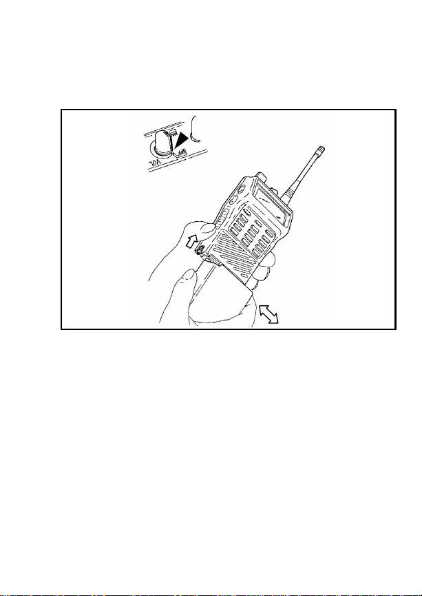
To remove the battery pack, push up on the battery
latch and slide the battery pack to the right. To replace
the battery , align the battery on the track and slide to the
left until a click is heard, indicating the battery is correctly
installed.
Figure 1 - Installing And Removing The Battery Pack
If the battery is to be charged on the radio, turn the
power switch on the radio to the off position before
charging. F ailing to turn the power s witch to off during the
charge cycle will result in a less than full charge condition,
which will noticeably reduce the operating time between
charges!
Normal battery operation time is 8 hours. This may
vary depending upon how much the receiver audio is
present and how much you transmit. The actual time may
vary from day to day depending upon operational requirements.
9
Page 10

FOR BEST PERFORMANCE
1. Charge battery to full capacity , 14 hours at the standard C/10 rate (capacity X .10). For "rapid" chargers,
allow additional time (2-3 hours) for "topping off" the
charge after it switches from "fast" to "slow".
2. Use the battery soon and use as much of the battery
capacity as possible or practical. A battery that is
charged and discharged completely will maintain the
longest running time capacity. Also, several
charge/discharge cycles are recommended to bring
a new battery up to its rated capacity.
3. Store and charge the batteries at room temperature
65°F to 75°F. Batteries that have been stored f or over
a month should be recharged before putting into
service due to chemical self-discharge which occurs
at a rate of approximately 1% per da y. Do not charge
cold batteries (40°F or below).
4. Reduced capacity or "memory effect" may result
from repeated identical shallow discharge/full recharge cycles. If such a condition is suspected, run
the battery until the instrumentation loses all power,
then fully recharge and discharge again. Repeat this
cycle 3-4 times.
10
Page 11

EXTENDED OPERATIONS
When operating in "Fringe Areas" at some distance
from the System, the other par ty may not receive your
transmission clearly . Also, you may notice that the background noise will increase on received signals. Moving
to higher ground or moving closer to the System will help
alleviate these problems. If moving closer to the System
is not practical, communication may be improved by
moving away from shielding structures. If you are in a
building interior, mo ve closer to a window (preferab ly one
generally in the direction of the System). At 800 MHz the
wave length is very short, sometimes moving a few
inches to a few feet can mak e significant signal strength
changes. Finding the best location can also be done
while listening to the background noise while moving
about; attempt to find a spot where the background noise
is reduced to a minimum or eliminated entirely. This may
make the difference from not being heard, to being heard
loud and clear when operating in the fringe areas of your
System coverage.
The fringe distance will vary greatly from plains areas ,
hilly terrain and mountain top sites.
11
Page 12

FCC LICENSING
This unit may or may not require a specific FCC
license to operate. The FCC requires all tr ansmitters
in the conventional and some Trunked Systems to be
licensed by the F ederal Communications Commission.
Some Tr unked operations a re now exempt from in dividual licen sin g r e qu ir e me nt s but must be op erat ed in
a licensed System.
Consult your dealer regarding specific licensing information, or contact the Federal Communications Commission.
For more information regarding the FCC license application (Form 571), call 717-337-1212, or contact the
FCC District Office nearest your location.
TRANSCEIVER SERVICE
There are no user serviceable components inside the
radio. Altering the inter nal components or adjustments
may result in illegal emissions, including off-frequency
operation, or damage to the radio.
Should an
display , or the LCD f ails to display information, or all icons
and display segments are shown, turn the POWER
ON-OFF/VOLUME control OFF then ON to reset the
microprocessor. Ensure that the battery is fully charged
and check that the antenna is securely tightened.
If the unit still fails to operate properly, refer to an
Authorized Service Center for servicing.
UNLOCK
condition be shown in the LCD
12
Page 13

INTRODUCTION
This manual describes how to use the EDA CS M-RK
II Portable Radio. The M-RK II is a synthesized, micr oprocessor-based, high performance portable FM radio
providing reliable two-way communications in both the
Enhanced Digital Access Communications System
(EDACS) trunking environment and conventional communication systems.
In the EDACS or trunked system mode, the user
selects a communications system and group. In this
mode, channel selection is transparent to the user and
is controlled via digital communication with the system
controller. This provides advanced programmable features and fast access to communication channels.
In the conventional mode, the user selects a channel
and directly communicates on that channel. In this mode,
a system refers to a set of channels. A channel is a
transmit/receive radio frequency pair.
The exact operation of the radio will depend on the
operating mode, the radio’s programming, and the particular radio system. Most features described in this
manual may be enabled or disabled through programming. Consult the system administrator f or the particular
features that are programmed into the M-RK II.
13
Page 14

USER INTERFACE
The M-RK II operating controls are located on the
radio’s front, top and left panels. A 15-button keypad,
liquid crystal display (LCD) for radio status information,
microphone and speaker are on the front panel. The top
panel houses a rotary SYSTEM/GROUP/CHANNEL
knob, POWER ON-OFF/VOLUME control knob and a
protected red EMERGENCY button. An OPTION button,
CLEAR/MONITOR button and the Push-To-Talk (PTT)
button are all located on the left side panel. The Universal
Device Connector (UDC) is located on the right panel
and is used while programming the radio and for accessory connection.
The keypad is used for manual number entry for
individual calls, access to a telephone interconnect system, and activation of various EDACS or conventional
features such as menu selection or scan operations.
The display has two, eight-alphanumeric-character
lines used to show the operational mode of the radio.
Fifteen status indicators, used to indicate various operating conditions such as transmitter on, channel busy,
scanning, or low battery, are located above and to the
right side of the character lines within the display. A back
light illuminates the display and the k eypad for nighttime
use.
14
Page 15

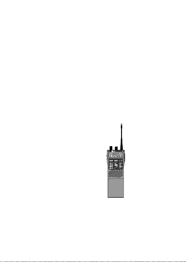
Figure 2 - M-RK II Portable Radio
15
Page 16
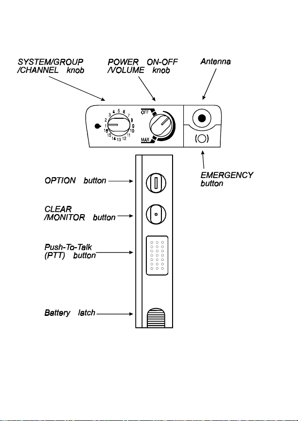
Figure 3 - Top And Partial Left Panel Views
16
Page 17

BUTTONS AND KNOBS
This section describes the primary function of the
button and knob controls. Other functions associated
with these controls are detailed in later sections.
SYSTEM
/GROUP
/CHANNEL
KNOB
PO WER
ON-OFF
/VOLUME
KNOB
Selects systems or groups/channels
(depending on programming). T his is
a 16 - position rotary knob. See SYSTEM/GROUP/CHANNEL SELECTION for details.
Applies power to the radio and adjusts the receiver’s volume. Rotating
the control clockwise out of detent
applies power to the radio. A single
alert tone sounds (if enabled through
programming) to indicate the radio is
operational.
Rotating the control clockwise increases the volume level. Minimum
volume levels may be programmed
into the radio to prevent missed calls
due to a low volume setting. While
adjusting the volume the display will
momentarily indicate the volume
level (i.e.
range is from a minimum programmed level of zero (displa yed as
OFF
the loudest level.
VOL = 31
in the display) up to 31 which is
). The volume
17
Page 18

EMERGEN-
CY/HOME-
BUTTON
The EMERGENCY/HOME button is
used to automatically select a desired Group and/or System by pressing and holding the button for a preprogrammed duration. The EMERGENCY/HOME button is also used
to declare emergencies by pressing
and holding the button for a pre-programmed duration. Emergency
messages may only be issued on
EDA CS system s.
OPTION
BUTTON
/MONITOR
BUTTON
18
CLEAR
(1) Programmable per system.
(2) Perf orms the backspace function
during data entry. In Phone and Individual Call modes the OPTION button can be used to recall the last
phone number or radio ID entered.
Serves several purposes depending
on the operating mode. In trunked
mode, the CLEAR/MONITOR b utton
exits the current operation and removes all displays associated with it.
The radio and display then return to
the group receive state. In conventional mode, pressing this button unmutes the receiver so activity on the
selected channel can be monitored.
When pressed and held for approximately 3 seconds, this button toggles
conventional channel decoding/encoding (Channel Guard, Digital
Channel Guard, T99) on and off if
Page 19
programmed for the selected channel.
PUSH-TO-
TALK BUT-
TON (PTT)
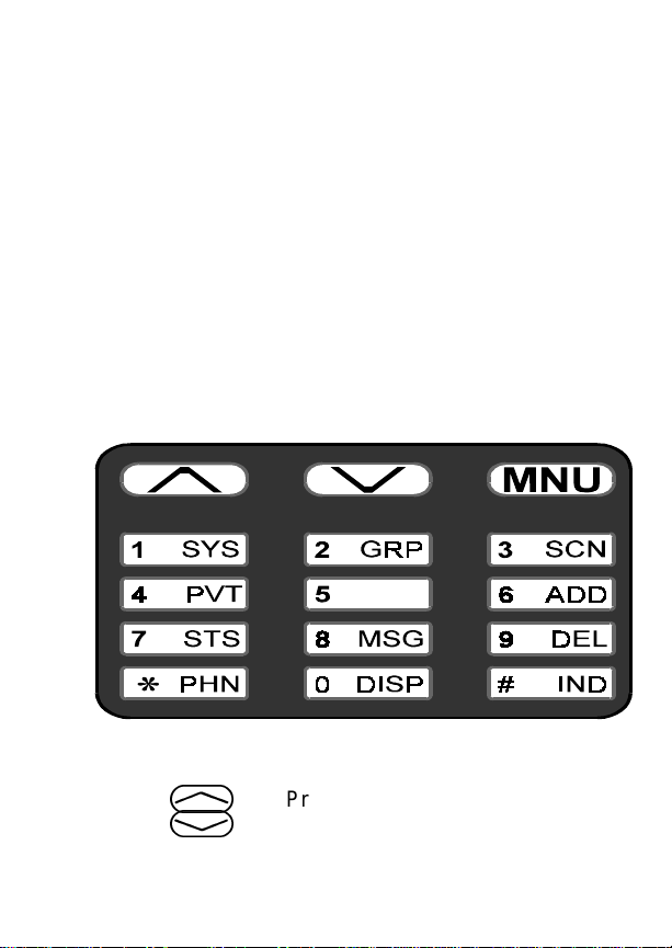
KEYP AD
The keypad layout is similar to a standard telephone
keypad but with three additional buttons at the top for a
total of 15 keys. In addition to numbers, most of the keys
have special functions and are labeled as such using a
symbol or abbreviated word describing its primary function. Numeric entry is a secondary function of the keys.
Each key is described below.
Enables the radio’s transmitter. Releasing PTT returns the radio to the
receive mode.
Figure 4 - M-RK II Keypad
,
.
Primary function - changes the s ys tem or group/channel (depending on
programming); secondary function changes to a selection for items
19
Page 20

within a list. Press
increasing order,
decreasing order. To auto-ramp
press and hold either key .
,
.
to scroll in
to scroll in
m
1
Primary function - accesses the
menu list. This is a list of additional
features that are not available directly from the keypad. See MENU
for details. Secondary function - activates a selected item within a list. After the menus list is accessed, select
a menu item from the list via
or
.
and activate it with this
key. Once activated,
ues its secondary function for activating a selected parameter setting
until the radio returns to its nor mal
receive state. This is similar to an enter key.
Used to directly access systems via
the keypad and to access system selection in increasing or decreasing
order, or to select a set (bank) of systems for SYSTEM/GROUP/CHANNEL knob selection (depending on
programming). See SYSTEM/
GROUP/CHANNEL SELECTION
for details.
m
,
contin-
20
2
Used to directly access groups via
the keypad and to access group selection in increasing or decreasing
Page 21
order, or to select a set (bank) of
groups for SYSTEM/GROUP/
CHANNEL knob selection (depending on programming). See SYSTEM/
GROUP/CHANNEL SELECTION
for details.
3
6
9
7
8
*
Toggles scan operation on and off.
When the radio is scanning, is
on and all groups or channels in the
scan list of the currently selected
system are scanned.
Adds or deletes selected groups or
channels from the scan list of the currently selected system. See the
trunked and conventional scan sections for details.
The Status key is used to send a preprogrammed status message to the
EDA CS site .
The Message key is used to send a
pre-programmed status message to
the ED ACS si te.
Used to place a telephone call
through the radio by selecting the
telephone interconnect special call
function. See Telephone Interconnect Calls for details.
SCN
#
Used to call an individual or make an
all-call by selecting the individual call
21
Page 22
special call function. See Individual
Calls for details.
0
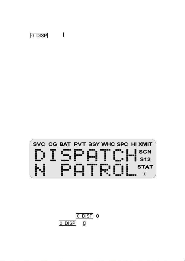
DISPLA Y
The radio’ s display is shown below . The two character
lines are used to display system, group and channel
names and also operational messages to the user. Each
line contains eight alphanumeric character blocks. The
15 status indicators are used to show the various operating conditions of the radio. If the display back-lighting
is programmed on, the display will illuminate for a short
period when any of the controls are operated.
Line 1
Line 2
The two display lines can be inverted to permit easy
viewing if the radio is worn on a belt or placed into a
vehicular charger. Press
acter lines, press
display. Refer to the MENU section to change the display’s contrast.
Inverts the display’s two alphanumeric character lines for viewing
from above; useful when the radio is
attached to the user’s belt.
Figure 5 - M-RK II Display
0
once to invert the char-
0
again to return to the normal
22
Page 23

Messages
During radio operation, various messages are displayed on either line one or line two. Typical messages
include control channel status information, such as system busy or call denied, or messages associated with the
radio’s operation, (i.e. volume or contrast adjust). These
messages are described below.
Message Name Description
QUEUED Call Queued
SYS BUSY System Busy
DENIED Call Denied
-
Trunked mode
only. Indicates
the system has
placed the call in
a request queue.
-
Trunked mode
only. Indicates
the system is
busy, no channels are currently
available, the
queue is full or an
individual call is
being attempted
to a radio that is
currently transmitting.
-
Trunked mode
only. Indicates
the radio is not
authorized to operate on the selected system.
23
Page 24

CC SCAN Control Channel Scan
-
Trunked mode
only. Indicates
the control channel is lost and the
radio has entered the Control
Channel Scan
mode to search
for the control
channel.
WA SCAN Wide Area Scan
TALKARND Talk-around
*RXEMER* Receive Emergency
24
-
Trunked mode
only. Indicates
the control channel is lost and radio has entered
the Wide Area
Scan mode to
search for a new
system (if enabled through
programming).
-
Conventional
mode only. Indicates the radio is
operating on
conventional
channels in talkaround mode (no
repeater).
-
Trunked mode
only . Indicates an
emergency call
Page 25

is being received.
This message
will be flashing
on line two.
*TXEMER* Transmit Emergency
VOL = 31 Volume Level
LOW BATT Battery Low
-
Trunked mode
only . Indicates an
emergency call
has been transmitted. This message will be
flashing on line
two.
-
Indicates the current volume lev el.
The volume level
display ranges
from OFF (silent)
to 31 (loudest).
-
Indicates the battery level is too
low for transmission. This message displays
when pressing
PTT and transmitting is disabled due to the
low battery condition.
UNKNOWN Unknown ID
-
Trunked mode
only . Indicates an
25
Page 26

individual call is
being received
by an unknown
radio ID. This bypasses when the
call is updated.
TX DATA Transmit Data
RX DATA Receive Data
DATA OFF Data Off
DATA ON Data On
-
Trunked mode
only. Indicates
when a data call
is being transmitted. Displayed on
line one.
-
Trunked mode
only. Indicates
when a data call
is being received.
Displayed on line
one.
-
Trunked mode
only. Indicates
when radio is in
data disable
state. Displayed
on line one.
-
Trunked mode
only. Indicates
when radio is
toggled to data
enable state. Displayed on line
26
Page 27

one for two seconds.
SYSC ON System Scan
Features On
SYSC OFF System Scan
Features Off
T99 ON Type 99 Decode On
T99 OFF Type 99 Decode Off
KEY ZERO Key Zero
-
Trunked mode
only. Indicates
the System Scan
features are enabled.
-
Trunked mode
only. Indicates
the System Scan
features are disabled.
-
Conventional
mode only. Indicates the T ype 99
Decode feature
is enabled.
-
Conventional
mode only. Indicates the T ype 99
Decode feature
is disabled.
-
Indicates that
cryptographic
keys have been
erased from radio memory .
PVT DIS Private Disabled
-
Indicates that the
group or channel
is not pro-
27
Page 28

grammed for private mode operation.
FRCD PVT Forced Private
NO KEY # No Key Number
Status Indicators
The 15 status indicators show the various operating
characteristics of the radio. The indicators show operating modes and conditions as follows:
SVC Trunked mode only .
ON - indicates the radio is in an EDACS
service area and is in communication with
the site controller via the control channel
(CC).
FLASHING - indicates the EDACS is in the
failsoft mode (if enabled through programming).
-
Indicates that
group or channel
is pre-programmed for private mode operation and clear
mode is not possible.
-
Indicates that the
correct cryptographic key is not
loaded for the selected group or
channel.
28
Page 29

OFF - indicates the radio is out of range or
the control channel is not available.
CG Conventional mode only.
ON - indicates Channel Guard encode/decode is enabled on the selected conventional channel.
FLASHING - indicates Channel Guard is
temporarily disabled.
BAT ON - indicates the battery pack’s charge is
low and needs recharging.
PVT Private
ON - indicates the group or channel is enabled to receive encrypted messages.
FLASHING - indicates an encrypted
transmission is being received.
BSY Channel Busy -
In trunked mode:
ON - indicates the radio is transmitting
or receiving a call on the working channel.
FLASHING - indicates a call has been
queued.
In conventional mode:
ON - indicates a call is being receiv ed.
WHC Who Has Called (trunk ed mode only)
ON - indicates an individual call has been
received, but not responded to . The indicator turns OFF if the individual call mode is
entered, the system is changed or the radio is turned off and back on.
29
Page 30

SPC ON - indicates the radio is in the special
call select/entry mode ( Individual or Telephone Interconnect).
HI ON - indicates the selected group or chan-
nel is selected to transmit at high power .
OFF - indicates the selected group or
channel is selected to transmit at low
power.
XMIT ON - indicates the radio is transmitting.
When operating in a trunked system, the
radio may be programmed to automatically transmit (without pressing PTT) to
maintain digital communication with the
site controller. will turn on whenever
the radio is transmitting.
SCN ON - indicates the scan mode is enabled.
FLASHING - indicates Scan is temporarily
disabled.
S ON - indicates the selected group or chan-
nel is in the scan list.
XMIT
30
1 ON - (conventional mode only) indicates
the selected channel is designated as the
priority-one scan channel.
2 ON - (conventional mode only) indicates
the selected channel is designated as the
priority-two scan channel.
Page 31

ON - (conventional mode only) indicates
that the selected channel has T99 decode
option enabled.
FLASHING - indicates Type 99 is temporarily disabled.
UNIVERSAL DEVICE CONNECTOR (UDC)
The Universal Device Connector (UDC) provides
connections for external accessories such as a headset
or a speaker-microphone. When the radio is locked in a
vehicular charger/repeater, the UDC provides the audio
and control connections between the radio and the vehicular charger/repeater. The UDC is also used to program and service the radio.
31
Page 32

ALERT T ONES
The M-RK II radio also provides audible alert tones
or "beeps" to indicate the various operating conditions.
These alert tones can be enabled or disabled through
programming.
Call Originate
A short mid-pitched alert tone sounds after keying the
radio (Push-T o-Talk button is pressed). This indicates the
radio has been assigned a working channel or that the
radio is transmitting on a conventional channel and voice
communication may begin immediately. In conventional
mode, this tone may be delayed after the PTT button is
pressed due to GE-STA R signalling (if enabled through
programming).
Autokey (Trunked Mode Only)
After being placed in queue or releasing the PTT
button prior to a working channel assignment, the site
calls the radio when a channel becomes available. At this
point, the radio automatically keys the transmitter
(autokey) for a short period to hold the channel. The radio
sounds a mid-pitched tone when it is clear to talk; immediately press the PTT button to keep the assigned channel.
Call Queued (Trunked Mode Only)
A high-pitched tone after pressing the PTT button
indicates the system has placed the call request in the
queue. The receiving unit(s) also hear the tones, indicating they will receive a call shortly . If the the PTT button is
32
Page 33

released, the radio will autokey whenever a channel
becomes available (see Autokey).
System Busy (Trunked Mode Only)
Three low-pitched beeps will be heard if the radio is
keyed when the system is busy, if no channels are
available for sending the message, if the call queue is
full, or if an individual call is being attempted to a radio
that is transmitting. Releasing the PTT button and reke ying initiates a new channel request.
Call Denied (Trunked Mode Only)
If the radio is keyed and a low pitched tone is heard
then the radio is not authorized on the system that has
been selected.
Carrier Control Timer
If the programmed time for continuous transmission
is exceeded, five short high-pitched warning tones followed by a long low-pitched tone will be heard. The
transmitter will shut down shortly after hearing the alert,
interrupting communications. Release and re-key the
PTT button to maintain communications. This will reset
the carrier control timer and turn the transmitter back on.
Low Battery W arning
A low-pitched tone is heard and comes on
indicating that the battery voltage is low. The radio will
continue to receive and transmit.
BA T
33
Page 34

Low Battery Alert (Transmit Lockout)
If the radio is keyed and the user hears either a
low-pitched tone or two tones and the LOW BATT status
indicator is displayed, the battery is discharged and the
radio will not transmit. Pressing the PTT or CLEAR
button will reset the LOW BATT status indicator if either
is pre-programmed to perform this function. The radio
will still be able to receive calls until the batter y is discharged beyond the point of operation, after which the
battery will need to be recharged to resume normal
operation.
Key Press Alert
A short tone or "beep" sounds to indicate a key has
been pressed. A short low-pitched tone indicates no
action was taken because the key is not active in the
current mode.
OPERA TION
KEYPAD LOCK/UNLOCK
The keypad can be locked at any time to prevent
undesired key presses. To lock the keypad when it is in
the unlocked state, press and release the
then within one (1) second press the OPTION button. All
buttons and keys except the PTT, OPTION,
CLEAR/MONITOR and EMERGENCY/HOME buttons
will now be inhibited. If the emergency function of the
EMERGENCY/HOME button is disabled, the home function will also be inhibited. If the button is enabled for
emergency or emergency/home function, the key is not
inhibited and an emergency can still be declared on the
m
key and
34
Page 35

home System/Group or the current System/Group (however programmed).
To unlock the keypad when it is in the locked state,
press and release the
second press the OPTION button.
TURNING ON THE RADIO
Rotate the POWER ON-OFF/VOLUME knob clockwise, out of detent to turn the radio on. (Ensure the
antenna and battery pack are properly connected prior
to power on.) A short beep (if enabled through programming) indicates the radio is ready for operation. The
display indicates, if programmed, the last selected system name on line one and the last selected group or
channel name on line two.
In the EDACS trunked en vironment, upon acquisition
of the control channel, will come on. If communi-
cation with the system’s control channel cannot be established, will not turn on. This may occur if, for
example, the radio is out of range of the trunking site. It
may be necessary to move to another location or select
another trunking system to re-establish the control channel link for trunked mode operations.
SVC
m
SVC
key and within one (1)
SELECTION MODE RULES
Many operations require selection from a list such as
system, group or phone number. This selection process
is handled in the same manner for all lists.
., m, 0- 9, *, #
OPTION button and the CLEAR/MONITOR button are
,
, the
35
,
Page 36

used during the selection process . The follo wing example
systems list is used to explain the process:
SYSTEM
1NORTH
2SOUTH
3EAST
4WEST
After entering a selection mode, the following generic
display format will appear.
XXXXXXXX
YYY =ZZZ
Line one shows the currently selected item name
(XXXXXXXX) from the list. Line two indicates the list
(YYY) that the selection is to be made from and the
number of the selected item (ZZZ) within the list. (In some
cases the information on lines 1 and 2 will be the opposite
of this example.) If SYSTEM 2 is the current selection,
the display appears as follows:
SOUTH
SYS = 2
Line one contains the current system name,
and line two,
system list and it is the second system within the list.
A new system from the list is selected by using
and
.
with the numeric keys.
the list in increasing and decreasing order respectively.
SYS = 2
or by directly entering the system number
, indicates that selection is from the
,
and
.
SOUTH
,
scroll through
36
,
Page 37

In the previous example, pressing
EAST system as shown in the next display.
EAST
SYS = 3
The radio may be programmed to wrap around from
one end of a list to the other end or to stop at the ends.
To directly access a selection, enter the corresponding number (i.e., 4) followed by
selection. Special calls (Individual Calls or Telephone
Interconnects) list selections or directly entered ID or
phone numbers are activated upon the press of the PTT
button and not
on line two as shown below. Line one shows the current
list being used for selection.
If a mistake is made while entering the number, press
the OPTION button to backspace once and correct the
entry . If an inv alid number is entered, a short low-pitched
tone sounds when
m
. The entered number is display ed
SEL SYS
m
is pressed.
.
m
4
selects the
to activate the
To exit the selection mode, press the CLEAR/MONITOR button or wait for the timeout. If the selection mode
is cleared while an entry is pending (i.e., numbers are
entered on line 2, but
entry on line two will be disregarded and the previous
selection will remain active. If the timeout activ ates while
an entry is pending, the entry on line two will be selected
if it is within the valid range; if it is out of range the entry
m
has not been pressed), the
37
Page 38

on line two will be disregarded and the previous selection
will remain active.
NOTE
While in system, group or channel selection mode,
the radio continues to receive calls normally and
continues scanning if it is enabled. If a call is received
during the selection mode process the radio will return to the normal rec eive mode display. Continuing
with the selection process will return the displa y to the
same point in the selection process if the selection
mode time out has not yet expired. Any press of the
PTT button during the selection mode process will
initiate transmission and exit the selection mode.
MENU
The menu function accesses features that are not
available directly from the ke ypad. The order and specific
number of menu items available is configurable through
programming. Upon radio power up, the menu item that
is at the beginning of the menu list will always be displayed first. Subsequent access to the menu function will
return the last menu item that was shown in the display.
To enter the menu mode, press
.
ing the selection process. All of the selection mode rules
previously detailed apply to the menu item selection
process with the exception of direct access. The radio will
continue to receive and transmit normally while in the
menu function.
, and the CLEAR/MONITOR button are used dur-
m
.
m, ,
,
A new item is displayed by using
to scroll through the list in increasing and decreasing
,
and
.
38
Page 39

order respectively. The displayed menu item is made
active by pressing
After entering the menu selection mode, the following
generic display format will appear.
Line one indicates the radio is in the menu selection
mode. Line two indicates the menu item (YYYYYYYY)
that is to be viewed or changed (some menu items
provide radio information and do not have changeable
parameters).
An example of the menu item selection process and
menu item parameter change is detailed below for the
backlight menu item.
m
.
ME N U
YYYYYYYY
PRESS:
The menu mode is entered.
PRESS:
PRESS:
The backlight menu item is activated and the display
will be similar to the following:
m
,
m
or
.
until the display shows:
ME N U
BCK LGHT
BCKL=XXX
YYYYYYYY
39
Page 40

Line one shows the active menu item and its current
parameter setting (XXX). Line two shows the currently
selected system or group name (YYYYYYYY).
The menu item’s parameter setting shown in the
display can now be changed by using
to scroll through the list of parameter values. Onc e the
desired setting is reached press
and return the normal display. For menu items that display radio information pressing
scroll through a list of informational displays. The menu
items are listed Table 1.
m
,
to store the value
,
or
or
.
.
will
NOTE
The TX POWER menu item, when selected,
toggles HI/LO power. It does not use
.
to scroll nor an additional press of the
m
button.
,
or
40
Page 41

Table 1 - Menu Item Information
FEATURE DISPLAY
Keypa d Lock KEY LOCK
Backlight Adjust BCK LIGHT
Contrast Adjust CONTRAST
Transmit Power Select TX POWER
Radio Revision REVISION
Invert (View) Display INVERT
Toggle Scan On/Off SCAN
Toggle Private Mode On/Off PRIV ATE
Display Current AEGIS
Encryption Ke y
Display Current Home
Group/Channel
Select Desired System SYS SEL
Add Group/Channel to
Scan List
Delete Group/Channel From
Scan List
Add/Delete Scan List SCAN A/D
Select Telephone Numbers
From Phone List
Toggle Data Operation On/Off NO DATA
Toggle Conv P1 Scan On/Off ECP1SCAN
Select Individual Call from IC
List
DISP KEY
HOME
SCAN ADD
SCAN DEL
PHN CALL
Trunked Only
Trunked Only
IND CALL
Trunked Only
41
Page 42

FEATURE DISPLAY
Select Status Message STATUS 0 - STATUS 9
Select Group GRP SEL
Toggle Talkaround Feat ure
On/Off
Select Channel CHN SEL
ProFile Select PROF ON, PROF OFF
Feature
Encryption Display
System Scan
Enable
Type 99 Decode Enable T99 ENAB
Trunked Only
Trunked Only
TALKARND
Conventional Only
Conventional Only
FEATURES
SYS SCAN
Trunked only
Conventional only
FEATURE ENCRYPTION DISPLAY
Feature Encryption Display is available through the
menu function and, if programmed, appears in the menu
FEATURES.
as “
” This data indicates current features
programmed into the radio as well as information required to add features to the radio. This feature applies
to 512K RAM radios only.
42
Page 43

Once the feature has been accessed, all normal
menu functions work. The user can scroll up or down
through all of the entries.
Feature Encryption Display provides the ability to
view, in the order displayed, the following:
Serial number ROM data - serial number of the ROM
•
Feature encryption data stream - used to enable
•
features
Number Fields - defines limits
•
Features enabled - displays bit fields of enabled
•
features
Serial Number ROM (12 Hex Digits)
Example:
When the user wants to enable a feature in his radio ,
he will need to call Ericsson Inc. They will ask for the ROM
serial number. The serial number shown here is for
example only.
43
Page 44

Feature Encryption Data Stream
Example:
These data streams define the features the user has
enabled in his radio and are required by Ericsson Inc. to
enable other features. The data streams shown here are
for example only.
FD2, FD3. All three are required.
Number Fields
Example:
Note:
There are three displays: FD1,
These number fields show the set limits of the of the
user’s radio as:
SG# -XXX - Maximum number of system/groups
•
combination available
44
Page 45

SY#_XXX - EDACS maximum trunked system limit
•
CH#_XXX - Maximum number of conventional chan-
•
nels available
The user needs to know the limits of his radio before
attempting to enable other featur es. The numbers shown
here are for example only.
Features Enabled
These numbers indicate which features are enabled.
Example:
The following numbers indicate features available in the
user’s radio.
Bit Fields Possible Features
01 Conventional mode Priority Scan
02 EDACS 3 Site System Scan
04 EDACS Group Scan operation
05 EDACS Priority System Scan
06 EDACS Wide Area System Scan/
PROSOUND
45
Page 46

Bit Fields Possible Features
07 EDACS Dynamic Regroup operation
08 EDACS Emergency operation
09 Type 99 Encode
10 Conventional mode Emergency
operation
12 AEGIS Digital Voice Operation
13 VGE encryption
14 DES encryption
15 User-defined speech encryption
16 Mobile Data operation
17 Status and Message operation
21 Alternate Language
22 Over The Air Personality
Programming (ProFile)
23 Narrow Band Operation 12.5 kHz
Channel Spacing
SYSTEM/GROUP/CHANNEL SELECTION
In the following description of SYSTEM/GROUP/
CHANNEL SELECTION, the term group is used for both
group and channel.
The M-RK II SYSTEM/GROUP/CHANNEL knob and
the
,, .
pair are programmable for maximum
flexibility. If the SYSTEM/GROUP/CHANNEL knob is
assigned to select groups, then the
,, .
keys
46
Page 47

are assigned to select systems. If the SYSTEM/GROUP/CHANNEL knob is assigned to select systems, then the
select groups. System, group and channel selection is
the primary function for these controls.
Either systems or groups can also be selected by
entering the select mode and following the selection
mode rules described earlier. Only the selection assigned as the primary function of the
will be available for this method of direct selection. For
example, if system selection is the primary function of the
,, .
be usable and direct group select will be unavailab le. The
system select or group select modes are entered by
pressing SYS or GRP, respectively, from the standard
receive mode. Using
particular selection mode in this manner is the secondary
function of these keys.
System Selection
Several methods, some of which depend on programming, can be used to select a new system. These procedures are presumed to be starting from the normal
receive display.
,, .
pair then only the system select mode will
,, .
keys are assigned to
,, .
after entering a
pair
METHOD 1: If system selec tion is programmed to the
SYSTEM/GROUP/CHANNEL knob, select a system by turning the SYSTEM/GROUP/CHANNEL knob to the desired system number position (1-16). The
display registers the new system name on
line one. If the knob is mo ved to a position
47
Page 48

greater than the number of programmed
systems, the highest programmed system
will remain selected.
METHOD 2: If system selection is programmed as the
primary function of
lect a system by pressing
.
to scroll through the system list.
The display registers the new system
name on line one.
,
and
.
,
, se-
or
METHOD 3:
48
Press
1
to enter the system select
mode and follow the selection mode rules
detailed earlier. If system selection is programmed to the SYTEM/GROUP/CHANNEL knob, direct access to systems will
not be available. Presses of
.
will scroll through different sets of
16 systems each (banks) if more than 16
systems are programmed into the radio.
The systems within each bank are then
selectable via the SYSTEM/GROUP/CHANNEL knob as described previously
in METHOD 1.
,
or
Page 49

Group And Channel Selection
Several methods, some of which depend on programming, can be used to select a new group or channel.
These procedures are presumed to be starting from the
normal receive display.
METHOD 1: If group selection is programmed to the
SYSTEM/GROUP/CHANNEL knob, select a group by turning the SYSTEM/GROUP/CHANNEL knob to the desired group number position (1-16). The
display registers the new group name on
line two. If the knob is moved to a position
greater than the number of programmed
groups, the highest programmed group
will remain selected.
METHOD 2: If group selection is programmed as the
primary function of
lect a group by pressing
to scroll through the group list. The display
registers the new group name on line two.
,
and
,
.
or
.
, se-
METHOD 3:
Press
mode and follow the selection mode rules
detailed earlier. If group selection is programmed to the SYSTEM/GROUP/
CHANNEL knob, direct access to groups
will not be available. Presses of
.
16 groups each (banks) if more than 16
groups are programmed into the radio.
The groups within each bank are then selectable via the SYSTEM/GROUP/CHAN-
2
to enter the group select
,
or
will scroll through different sets of
49
Page 50

NEL knob as described previously in
METHOD 1.
EMERGENCY/HOME BUTTON DEFINITION
The EMERGENCY/HOME button can be pro-
grammed in one of the following conditions:
1. Emergency Enabled and Home Enab led - The radio
will switch to the programmed home System and/or
Group and send an emergency transmission.
2. E mergency Enable and Home Disabled - The radio
will send an emergency transmission on the current
System/Group.
3. Emergency Disab led and Home Enabled - The radio
will switch to the home System and/or Group.
4. E mergency Disabled and Home Disabled - the button is not active.
Home
The radio can be programmed to automatically switch
to a home System and/or Group by pressing and holding
the EMERGENCY/HOME button for the pre-programmed duration. The radio will also transmit an emergency message on the home System and/or Group if
programmed (see the Emergency Operation section).
50
Page 51

AEGIS AND VOICE GUARD OPERATION
Voice Modes
Each system (trunked or conventional) in the radio is
programmed for either Aegis or Voice Guard communications. Aegis programmed systems have three (3) different voice modes: clear (analog), digital and private.
Voice Guard systems have two (2) voice modes: clear
(analog) and private. The voice modes are programmed
on a per-group basis within each trunked system and on
a per-channel basis within each conventional system. A
radio must be equipped with the encrypt/decr ypt option
before it will operate in Aegis or Voice Guard modes.
TRANSMIT/RECEIVE MODE COMPATIBILITY
FOR AEGIS OPERATION
GROUP/CHANNEL
PROGRAMMING
(TRANSMIT)
CLEAR Yes No No
DIGITAL Yes Yes No
PRIVATE Yes No Yes*
CLEAR
RECEIVE
DIGITAL
RECEIVE
PRIVATE
RECEIVE
*assumes the proper cryptographic key is loaded
51
Page 52

TRANSMIT/RECEIVE MODE COMPATIBILITY
FOR VOICE GUARD OPERATION
GROUP/CHANNEL
PROGRAMMING
(TRANSMIT)
CLEAR Yes No
PRIVATE Yes Yes*
CLEAR
RECEIVE
PRIV ATE
RECEIVE
*assumes the proper cryptographic key is loaded
NOTE
Conventional Aegis or encrypted channels
require Channel Guard on the channel to operate
correctly.
Clear Modes
Aegis clear and Voice Guard clear modes are identical voice modes in which the radio transmits and receives
only clear (analog) voice signals. These analog signals
are non-digitized and non-encrypted. Clear mode transmissions can be easily monitored by unauthorized persons. Groups or channels programmed for clear operation cannot transmit or receive Aegis digital or private
messages.
Aegis Digital Mode
Aegis digital mode allows the radio to transmit and
receive digitized voice signals. Aegis digital signals pro-
52
Page 53

vide improved weak signal performance and they cannot
be easily monitored with a standard receiver. Groups and
channels programmed for Aegis digital operation transmit only digital signals. Private calls cannot be received
or transmitted when the radio is in the Aegis digital mode
because the radio does not know the cryptographic key
used. Message trunked group calls and individual calls
will be answered back in the mode they were received,
assuming the call or hangtime is still active. Individual,
phone, all and emergency calls will be transmitted clear
if digital mode is disabled or inoperative.
1. If receiving an analog message trunked call, the
radio will respond in analog mode during the hang
time on the working channel.
2. If receiving an analog I-Call, the radio will respond in
analog mode during the hang time.
3. When using the "WHC" feature to respond to an
I-Call (after the hang time has expired), the call will
be transmitted in the mode defined by the system
mode as programmed for the current system if the
ID being called is not in the I-Call list. If the ID is in
the I-Call list, then the call will be transmitted as
defined by the I-Call mode programmed in the list for
that ID.
DTMF
The overdial and hot ke ypad f eatures f or tr ansmitting
DTMF tones are not available while in the Aegis Digital
Mode.
53
Page 54

Error Messages
If either of the following error messages is display ed,
the radio was either programmed incorrectly or needs
servicing:
DSP ERR
ERR=xxxx
DSP ERR
Po wer Up Only
If the Aegis circuit board is not responding, the following error message will be displayed and the radio needs
servicing:
HARDWARE
ERR= 30
AEGIS PRIV ATE AND VOICE GUARD
PRIVATE MODES
The Aegis private and Voice Guard private modes
allow the radio to transmit encrypted messages and
receive clear or private transmissions. The radio will
transmit private if the group/channel is programmed for
private operation and forced operation is pre-programmed. If autoselect operation was pre-programmed
and the radio is in private mode, the radio will transmit in
the mode of the received call if the hang time is active. If
no hang time is active, the radio will transmit private.
Aegis transmissions cannot be received by a radio set
to receive a Voice Guard transmission. Accordingly, a
V oice Guard transmission cannot be received by a radio
set to receive an Aegis transmission.
54
Page 55

Cryptographic keys are transferred to the radio using
a cryptographic Keyloader. Up to seven (7) different
cryptographic keys, numbered 1-7, can be transferred
from a Keyloader and stored in the radio. An individual
key is automatically selected on a per-group/channel
basis according to the radio’s programming. Groups and
channels within Aegis systems can be programmed for
keys 1-7. Groups and channels within Voice Guard systems can be programmed for keys 1-7. Up to 8 banks of
7 keys can be stored for Aegis (DES and VGE) systems
and up to 4 banks of 7 keys for V oice Guard systems. The
bank is specified per system.
DES radios require a DES Keyloader (Option V4025
with software version 3.N or later). VGE radios require a
VGE K eyloader (Option V4028 with software version 2.N
or later).
When operating on a group or channel programmed
for private mode, all transmissions will be private transmissions and the radio will receive clear and private
signals. The status flag in the display turns on when
the private mode is enabled. If the selected group or
channel is programmed for autoselect capability, the
mode may be toggled between private and clear with the
PVT button. Radios programmed for forced private operation do not allow a change of the transmit mode;
therefore, the PVT button has no effect.
PVT
T ransferrin g Keys Into The Radio
The following procedure outlines basic key transferring steps.
1. Turn the radio off.
55
Page 56

2. P lug the modular connector of the Keyloader cable
into the Keyloader modular jack.
3. Connect the Keyloader cable to the UDC on the
radio.
4. Press the PWR button on the Ke yloader and wait for
the Keyloader to display "MASTER MODE".
5. Press the TRN button on the K eyloader. If necessary,
select a different cryptographic key to be transf erred
into the radio.
6. Turn the radio on. The top line on the radio display
will read "KEY LOAD" and the second line will read
"BANK = N" where N= keybank number. Press the
,
beep will indicate that the Keyloader is connected.
7. P ress the EXE button on the Keyloader to transfer
the key. The Keyloader will display "GOOD 1.x
TRANSFER" where "x" is the selected cryptographic
key number.
8. Disconnect the cabl e from the radio’s UDC . The radio
will change to the selected group or channel as
indicated in the display.
or
.
button to select the keybank. A
Displaying The Currently Used Cryptographic K e y
Number
To display the cryptographic key currently in use for
either the system encryption key (for special call such as
individual, phone, all, agency or fleet) or the group/chan-
56
Page 57

nel key (for group or conventional calls), perform the
following procedure:
1.
2.
Press the
Use the
m
,
button.
or
.
button to select "DISP
KEY".
3.
Then use the
,
or
.
button to toggle
between displaying the system key or the
group/channel key.
ENCRYPTION KEY
DISPLAYED
System
Group/Channel
MESSAGE DISPLAYED
"SYS KEY"
"KEY = 1"
"GRP KEY"
"KEY = 2"
Key Zero
All cryptographic keys can be zeroed (erased from
radio memory) by pressing the MONITOR/CLEAR b utton
and while still pressing this button, press and hold the
OPTION button. Press both buttons for 2 seconds. A
series of beeps will begin at the start of this 2 second
period and then switch to a solid tone after the keys have
been zeroed. The display will indicate "KEY ZERO"
If the cryptographic key(s) are zeroed, one or more
keys must be transferred from the Keyloader into the
radio before private communications may continue.
57
Page 58

PRIVATE OPERATION
Receiving An Encrypted Call
When receiving, the radio automatically switches between clear or private operation. If the transmission being
received is an encrypted transmission, it will be decrypted, the status flag will flash, the receiver will
unsquelch and the message will be heard in the speaker.
For this to occur, the selected group or channel must be
programmed for private operation and the correct cryptographic key must be loaded into the radio.
Transmitting An Encrypted Call
1. Select the desired group or channel.
2. Place the radio in private mode by pressing the
4
PVT
If the last state of the radio was private mode, the
private mode will be enabled on power up. Also the
private mode will be enabled if forced operation has
been programmed in the radio.
PVT
key. When private mode is enabled, the
status flag will be on.
If a group or channel is not programmed for private
mode operation, "PVT DIS" will be displayed if an
attempt is made to enable private transmit mode. It
is not possible to operate on this group/channel in
private mode.
58
Page 59

If the radio is programmed for forced private tr ansmit
operation, "FRCD PVT" will be displayed if an attempt is made to disable private transmit mode. It is
not possible to transmit on this group/channel in
clear mode.
If the radio does not have the correct encryption key
loaded, "NO KEY #" will be displayed and the call will
not be transmitted.
3. Continue with standar d transmission procedures. A
private mode access tone will be heard when the
PTT button is pressed.
Scanned Group Calls
Receiving a scanned group call is the same as receiving a selected group call. During the scan hang time, if
the radio was programmed for autoselect, it will transmit
back in the same mode it received the call. For e xample,
if a clear group is entered in the scan list, it will only
receive clear calls. If the same group was available in
private and entered in the scan list, it can receive clear
and private calls, provided autoselect was programmed
in the radio. The user can select transmitting on the
scanned or selected group. If a group is entered in the
scan list more than once and in different modes (clear,
digital, private), only the first occurrence of the group will
be used.
59
Page 60

LAST SYSTEM/GROUP OR CHANNEL RECALL
(SUPERVISORY RADIO UNITS ONLY)
This feature enables the user to recall the last selected system/group after an EDACS emergency or
home function, a conventional emergency or home function or system/group key function. This feature must be
pre-programmed as "Enabled" to function. For e xample,
if the Home button (pre-programmed) is pressed, the
radio will go to the designated Home system/group or
channel. If the Home button is pressed again, the radio
returns to the previous system/group or channel. At this
time the user can toggle between the Home system/group or channel and the previous system/group or
channel.
60
Page 61

EDA CS TR UNKED MODE OPERATION
Digital trunking provides fast communication access
at all times, even during busy hours. In this mode the
operator selects a communications system and group,
and the audio communication or working channel (WC)
is allocated through digital signalling with the site.
RECEIVING A CALL
1. Turn on the radio by rotating the POWER ON-
OFF/VOLUME knob clockwise (out of detent). A
short aler t signal (if enabled through programming)
indicates the radio is ready to use.
2. The display shows the last selected or the power up
(depending on programming) system and group
names and indicates if the radio has acquired the
system control channel by turning on . If the
radio is unable to obtain a control channel, line two
shows CC SCAN and will remain off .
3. A djust the POWER ON-OFF/VOLUME knob to the
desired volume level.
4. S elect the desired system and group. The display
indicates the current system and group names.
SVC
SVC
5. The radio is now ready to receive calls.
61
Page 62

6. G ROUP CALL - When the radio receives a group
call, it unmutes on the assigned working channel and
BSY
comes on. Line one shows GR f ollowed by the
logical ID number (if received) of the unit sending the
message, or the associated name if the ID number
is found in the individual call list.
7. INDIVIDUAL CALL - When the radio receives an
individual call (a call directed only to the user’s radio),
it unmutes on the assigned working channel and
turns on and . Line one shows ID followed by the logical ID number of the unit sending
the message, or the associated name if the ID number is found in the individual call list.
Responding to the call prior to the programmed
call-back time-out will automatically direct the call to
the originating unit. If the caller’s ID is not received,
UNKNOWN will display and there will be no call-back
hangtime.
SENDING A CALL
1. T urn on the radio and set the PO WER ON-OFF/VOLUME knob to the desired volume level. Select the
desired system and group.
BSY
WHC
2. Press and hold the PTT button. The radio will display
XMIT
, the system and group names and perform
the necessary signalling r equired to obtain a communication channel.
62
Page 63

3.
When the working channel is assigned, and
BSY
are turned on and a short beep sounds indicat-
ing that communication can begin.
XMIT
NOTE
If two or more tones, or a high pitched tone is
heard, the system may be busy and the call
request has been placed in queue or the request
has been denied for some reason. Refer to the
ALERT TONES section for more details.
4. Hold the radio approximately three inches from the
mouth and speak in a normal voice into the microphone (located between
keypad).
5. Releas e the PTT button when the transmission is
complete and listen for a reply.
CONVENTIONAL FAILSOFT
In the unlikely event of a failur e of the EDACS System,
communications may take place in conventional failsoft
mode. The radio will be automatically directed to a
communications channel set up for this purpose. During
this mode of operation, the control unit will display
in the alphanumeric display. An increase in activity
FS
on the channel during conventional failsoft operation may
be noticed, so be careful not to transmit until the channel
is clear.
,
and
.
on the
CONV
Operation during conventional failsoft will be the
same as operation on a conventional system, except that
63
Page 64

it will not be possible to select a communications c hannel, or use emergency and special call. When trunking
is restored, the radio will automatically be returned to
normal operation.
NOTE
Emergency and Special Call are not operational
during conventional failsoft. Also, the
control will not operate.
SCAT OPERATION
A SCAT (Single Channel Autonomous Trunking) System operates with the same set of features as a standard
EDACS system. The only significant user change relates
to the
BSY
indicator. Since only one channel, operating
as both control and working channel, exists in a SCAT
System, the
channel is in the working channel mode. When the
transmission on the channel is completed, the indicator
turns OFF and indicates the return of SCAT control
channel signaling.
EMERGENCY OPERATION
BSY
indicator will be ON when the SCAT
GROUP
The radio’s ability to declare an emergency, clear an
emergency , remain locked on an emergency system and
group, and the emergency audio and display freeze can
each be enabled or disabled through programming.
When an emergency is declared, scanning will stop and
restarts only after the emergency has been cleared.
64
Page 65

Receiving An Emergency Call
When receiving an emergency call from the selected
group and system, an alert beep is heard and
comes on. The message
play on line two until the emergency condition is cleared.
Follow standard emergency procedures.
Declaring An Emergency Call
To send an emergency call to the selected sy stem
and group (or on an optionally preprogrammed group),
proceed as follows:
1. Press and hold the red EMERGENCY button that is
on top of the radio in front of the antenna for approximately one second (this time is programmable and
therefore could be longer or shorter; check with the
system administrator). The radio will transmit an
emergency call request with the radio ID until an
emergency channel assignment is received.
2. W hen the working channel assignment is rec eived,
the radio sounds a single beep (Autokey alert tone)
indicating it is ready for voice transmission.
*TXEMER*
emergency is cleared.
flashes on line two in the display until the
*RXEMER*
flashes in the dis-
BSY
3. Press PTT and speak into the microphone in a
normal voice. turns on.
4. Release PTT when the transmission is complete and
listen for a reply.
BSY
65
Page 66

5. The emergency can be cleared by pressing and
holding the CLEAR/MONITOR button followed by
pressing the EMERGENCY button then releasing
both buttons.
SCANNING TRUNKED SYSTEMS
The following features allo w interaction with systems
other than the selected system to meet specific customer
needs. Wide Area System Scan and ProSound are
mutually exclusive options; however, Priority System
Scan will operate while ProSound is active.
The radio can be programmed with the following
System Scan features. These features are automatically
enabled upon radio power up. A key or menu option is
also defined to allow the System Scan features to be
toggled during radio operation. This is covered in the
MENU SELECTION and PRE-PROGRAMMED KEYPAD KEY sections. The System Scan state will be
maintained through system changes but will default to
ON at power up.
Wide Area System Scan
The M-RK II radio may be programmed for wide area
system scan operation for multi-site applications. Upon
the loss of the currently selected system’s control channel, radios may be programmed to automatically scan the
control channels of other systems. If a new control channel is found, the radio will switch to the new system and
sound an alert tone.
66
Page 67

ProSound
The radio may be progr ammed f or ProSound system
scan operation for multi-site applications. ProSound
scanning is an enhanced replacement for wide area
system scanning. This algorithm insures that the radio
continually receives high quality audio. When the selected system degrades to a pre-programmed level, the
radio changes to the new system and sounds a tone.
Should the control channel be lost completely, the radio
will scan the adjacent systems until a suitable one is
found.
Priority System Scan
The radio may also be programmed for priority system scan. A priority system may be assigned among the
systems programmed into the radio. Radios programmed
in this manner will check for the priority trunked system’ s
control channel at a programmable rate ranging from 1
to 16 minutes. This priority scan timer is reset each time
the PTT button is pressed or when a call is received. If
the priority system control channel is found, the r adio will
automatically switch to the priority system.
Menu Selection
Press
M
to scroll through the selections until SYS SCAN is displayed. Then press
state. T he SY SC ON or SYSC OFF display message is
displayed f or two seconds to show the new state.
and then use the
M
to toggle the System Scan
< >
control
67
Page 68

Pre-Programmed Keypad Key
Press the pre-programmed key and the SYSC ON or
SYSC OFF display message is displayed for two sec-
onds to show the new state.
SCANNING TRUNKED GROUPS
Groups which have been previously added to the
scan list on a per system basis may be scanned. Each
system’s group scan list is retained in memory when the
radio is turned off or when the battery pack is removed.
The following procedures outline scan operations for
trunked groups. See the conventional mode operating
procedures for specific procedures on conventional
channel scanning.
Adding Groups To A Scan List
1. W ith scan operation turned off, select the desired
group to add to the selected system’s group scan list.
2.
Press
6
system’s group scan list will show when it is the
selected group.
Deleting Groups From A Scan List
1. W ith scan operation turned off, select the desired
group to delete from the selected system’s group
scan list.
S
. comes on. Any group that is in a
S
68
Page 69

NOTE
Scan will be disabled temporarily when an
emergency is declared.
2.
Press
9
system’s group scan list will not show when it is
the selected group.
A group can also be deleted from the scan list, if it is
not the currently selected channel, by pressing
during scan operation while the radio is displaying the
unwanted group. The group will be deleted from the
system’s group scan list in the same manner as if done
using the steps above. Deletions done in this manner will
not remain deleted if the radio is turned off and then back
on.
Nuisance Delete
A group can also be deleted from the scan list, if it is
not the currently selected group, by pressing the
key during scan operation while the radio is displaying
the unwanted group. The group will be deleted from the
system’s group scan list in the same manner as if done
using the steps above. Deletions done in this manner will
not remain deleted if the radio is turned off and then back
on.
Turning Scan On
S
. turns off. Any group that is not in a
S
9
9
1.
Toggle scan operation on by pressing
will turn on when the radio is scanning.
3
SCN
.
69
Page 70

NOTE
Scan will be disabled temporarily when an
emergency is declared.
2. W hen a group on the scan list receives a channel
assignment, the radio unmutes on the assigned
channel and c omes on. Line one shows
followed by the logical ID number (if received) of the
unit sending the message, or the associated name
if the ID number is found in the individual call list. The
group name displays on line two.
If the radio detects a call from the currently selected
-
group, it has priority and the radio will switch to the
selected group call.
The radio will continue scanning if a new group is
-
selected when scan is on.
Pressing the PTT button when scan is on will cause
-
the radio to transmit on the display ed group or to the
currently selected group (depending on programming).
BSY
GR
Pressing
-
to recall the scanned group that was last received.
This group is recalled for a period equal to the scan
hang time.
Turning Scan Off
Toggle scan operation off by pressing
radio will resume operation on the selected group.
70
6
when scan is on will cause the radio
3
. Th e
Page 71

PROGRAMMABLE ENTRIES
Individual call ID numbers, telephone numbers and
other number sequences for overdialing are stored in the
special call lists when programming the radio. The first
ten entry locations of these lists can be changed by the
radio operator. The keypad is used when adding, changing and storing numbers in these entry locations.
Use the following procedure to store a number in one
of the first ten entries of a special call list:
1.
Press
#
or
*
to enter the individual call list
or the phone call list. turns on. The selection
mode rules apply.
2.
Scroll through the list using
one of the first ten entries is reached.
displayed if the location is empty.
3. Enter the desired number . If necessary, a pause can
be entered by pressing and holding
*
display. The individual call list entries will accept up
to 5 digits. The phone call list entries accept a combination of up to 31 digits and pauses.
or
#
SPC
,
or
.
until
NO ENTRY
0- 9
until an underscore appears in the
is
,
4.
Press and hold
indicating that the number has been stored.
5. Repeat the steps above if the number stored in an
entry location needs to be changed.
m
until the display changes
71
Page 72

INDIVIDUAL CALLS
Receiving And Responding To An Individual Call
(Trunked Mode Only)
When the radio receives an individual call (a call
directed only to the user’s radio), it unmutes on the
assigned working channel and turns on the indicator. Line one shows ID followed by the logical ID
number of the unit sending the message, or the associated name if the ID number is found in the individual call
list. The individual call indicator display
played on line two . The radio can be programmed to ring
when an individual call is received. If enabled, the ring
begins five seconds after the caller unkeys and will
continue until the PTT button, the CLEAR button or
#
grammed call-back time-out, the call will automatically be
directed to the originating unit. If a response is not made
before the call-back time-out, the radio will return to
normal receive mode, but will be displayed. If the
caller’s ID is not received,
duration of the call and there will be no call-back hangtime.
is pressed.
If a response is made to the call prior to the pro-
WHC
UNKNO WN
will display for the
BSY
*INDV*
is dis-
To respond after the call-back time-out, press the
#
on the first line and
the PTT button at this point will initiate an individual call
back to the original caller. (If the last call was a group
call, the display will show
button will place the call as an individual call.) The radio
key. The radio’s display will show the caller’s ID
WHCI=1
on the second line. Pressing
WHCG=1
. Pressing the PTT
72
Page 73

stores the ID’s of the last 10 callers in the Calls Received
List as shown. Individual calls are stored in the top half
of the list (1-10), and group calls are stored in the bottom
half of the list (1-10). The most recent call is stored in
position 1, the second most recent call is stored in
position 2, etc.
To access the list, press the
the
,
or
.
keys to scroll through the list.
Pressing the
since the call was received.
m
key will display the time elapsed
#
key twi ce. Use
73
Page 74

Call Storage Lists
There are two lists available for call storage in the
radio, the calls received list (1-10) and the personality list
(1-99 as defined by the user). When the individual call
mode is entered by pressing
list is available. The user can toggle to the personality
list by selecting any key other than
between the two lists by pressing the
is enabled, the calls received list wraps on itself and not
into the other list.
The saved call list shows all ten storage locations. If
no calls have been received, the saved call list will be
empty and the pre-stored list will be available upon
entering the individual call mode.
#
, the calls received
0
#
(or toggle
key. If wrap
When in the saved call list, pressing
the time stamp on and off. The time stamp indicates how
long ago the call was received. The display indicates this
information as HH:MM:SS where HH=hours, MM=minutes and SS=seconds.
m
toggles
74
Page 75

When in the pre-stored list, pressing
the Logical IDentification (LID) on and off.
Sending An Individual Call (Trunked Mode Only)
The following procedures describe how to initiate and
complete an individual call.
1. To select a previously stored individual, select the
I-Call mode from the menu or press
by the RAMP control
through the list of stored individuals. The selection
mode rules apply . While in the individual call list, the
m
name and the unit ID number. If the individual is not
stored in this list but the individual’s unit ID is known,
it can by entered directly from the keypad.
2. Press the PTT b utton; the radio perf orms the necessary signaling to obtain a communication channel.
When the signalling is complete and the radio is clear
to transmit, indicator turns on and the channel
access tone sounds. Line one shows the called
individual’s name if f ound in the list of stored individuals or
being called. The message
two. Proceed with the message.
key will toggle the display between the call
XMIT
ID
followed by the logical ID number of the unit
,
*INDV*
m
#
or
.
displays on line
toggles
followed
to scroll
75
Page 76

TELEPHONE INTERCONNECT CALLS
Receiving A Telep hone Inter connect Call (Trunked
Mode Only)
Receiving a telephone interconnect call is identical to
receiving an individual call. See the DTMF Overdial
Operation section if access to ser vices requir ing "overdial" is needed. Over dial operations are av ailable f or any
special call whether it is an individual call or a telephone
interconnect call.
Sending A T elephon e Inter connect Call ( Trunked
Mode Only)
Use the following procedures to initiate and complete
a Telephone Interconnect call:
1. To select a previously stored phone number, press
*
the list of stored phone numbers. turns on. The
selection mode rules apply. If the phone number is
not stored in this list but the phone number is known,
it can be entered directly from the keypad. If necessary, a pause can be entered by pressing and holding
derscore appears in the display. The last entered
phone number can be recalled by pressing the OPTION button.
followed by
0 - 9
,
*
,
or
.
SPC
or
#
to scroll through
until an un-
2. Press and release the PTT button; the radio performs
the necessary signalling to obtain a communication
channel. When the signalling is complete and the
radio is clear to transmit, turns on, turns
XMIT
BSY
76
Page 77

off and the channel access tone sounds. Line one
shows the accompanying name if selected from the
list of stored numbers or the phone number if entered
directly . T he message
The radio then automatically transmits the programmed number stored in the special call queue.
3. The telephone ringing will be heard. When someone
answers the phone, press the PTT button and speak
into the microphone. Release the PTT button to listen
to the callee. Unsuccessful interconnect signalling
returns the radio to the normal receive mode and the
number remains displayed until the special call is
cleared or the time-out expires or another group or
system is selected. Terminate a call by pressing the
CLEAR/MONITOR button.
*PHONE*
displays on line two.
NOTE
The M-RK II radio is capable of simplex (one wa y)
conversation only. The callee can only hear the
radio if the PTT button is pressed (the radio is
transmitting) and the callee can only be heard
when PTT is released (the radio is receiving).
4. To terminate the call, momentarily press the
CLEAR/MONITOR button.
DTMF Overdial/Con ventional Mo de Telephone
Interconnect
Once the radio has established a connection to the
public telephone system, it may be necessary to "overdial" more digits to access banking services, answering
machines, credit card calls or other types of systems that
77
Page 78

require DTMF (Dual-Tone Multi-Frequency) access digits. Overdial operation can also be used to initiate a
telephone interconnect call via DTMF signalling if a dial
tone has already been accessed on the system. This is
the method that is used for making a telephone interconnect call while operating in the conventional mode but will
also function in trunked mode if a dial tone is directly
accessible. Telephone numbers and other number sequences for overdialing can be stored in the phone list
when programming the radio or stored by the operator in
the first ten phone list entries. These numbers are accessed by pressing
mode rules.
The following steps are required to dial these numbers:
1. Follow the procedure in Sending A Telephone In-
terconnect Call (Trunked Mode Only) to establish
a connection to the telephone system or consult the
system administrator for the procedure to access a
dial tone on the trunked or conventional system.
2. Overdial numbers are transmitted using either
method below:
METHOD 1: Press and hold PTT while entering the
*
then following the selection
overdial number sequence from the keypad. This method sends DTMF tones during individual, telephone interconnect,
trunked group or conventional channel
calls. Anytime the PTT button is pressed
and held, the keypad is enabled f or DTMF
entry .
78
Page 79

METHOD 2:
PORTABLE DATA
When operating in the EDACS configuration, M-RK
radios permit either voice or data calls to be transmitted
or received. The radio can handle only one type of call
at a time; however, selection of either data or voice is
elected transparently by the operator through normal
usage of the radio. Data communications is not supported in the conventional mode. D A TA, RS2-Type DAT A,
and ProFile are EDACS enhanced, separately purchased features that when turned on can be used to
configure M-RK radios.
Press
lect/entry mode and follow the selection
mode rules to call up a stored number
from the phone list or to directly enter the
overdial digits. turns on. Press PTT
to send the overdial sequence once. If the
number needs to be transmitted again, it
must be selected or entered again (this
prevents unwanted numbers from being
sent the next time the PTT button is
pressed during the call).
This overdial select/entry mode remains
active until the call is dropped, cleared, or
m
try mode can be re-entered if the call is still
active by pressing
*
to enter the overdial se-
SPC
is pressed. The ov erdial select/en-
*
.
"Data" now applies to two classes of data: External
Device Data Applications (Mobile Data Terminals ) and
Radio Destined Data Applications (ProFile). For External Device Data Applications, both destination and
79
Page 80

source are from applications external to the radio. For
Radio Destined Data Applications (ProFile) one side of
the conversation is an e xternal device (i.e ., ProFile Mangager), but the other side is now an application internal
to the radio. Data applications can be common between
both application classes, or specific to a data application.
Each programmable data option is organized as the
following:
Universal Options - Apply to ALL data applications.
•
Specific Options - Apply only to either ProFile or
•
MDT.
The radios can be connected to Mobile Data Ter minals (MDT) or to a host computer/radio. A host radio
routes all data (MDT and ProFile) externally . Any RS-232
compatible device that supports the Radio Data Interface
(RDI) protocol (V ersion 1.91 or higher) may be connected
to the radio. Support for MDT’s or host computers is a
programmable option per radio. Additionally, radio programmed for host computers may also be programmed
for data only operation (no voice calls transmitted or
received).
Data Displays
The following will be displayed during the various
states of data mode operation:
TX DATA Shown on top display line when the
radio is transmitting a data call.
RX DATA Shown on top display line when the
radio is receiving a data call.
80
Page 81

DATA OFF Shown on top display line when the
radio is in the data disabled state.
DATA ON Shown for two seconds on top display
line when the radio is toggled to the data
enabled state.
Data Off Operation
DATA OFF suspends TX/RX data activity until it is
re-enabled via DATA ON. When the data state is disabled, the display shows "DAT A OFF" on the top line. The
radio can be placed in the data disabled state by any of
the following methods.
Declaring an emergency (not to be used unless an
•
actual emergency condition exists). Aler t tone will
sound.
Pressing the OPTION button (if pre-programmed f or
•
no data key). Alert tone will sound.
Pressing the no data (ND) key (pre-programmed).
•
NOTE
If DATA OFF is active, neither ProFile nor MDT
will function.
Data On Operation
DATA ON/OFF applies to all radio data (i.e., MDT and
ProFile). D AT A ON will be displayed on the top line in the
display for two seconds then the display returns to normal. The data state is enabled by one of the following
(depending on how it was disabled).
81
Page 82

Pressing the no data (ND) key toggles data state on
•
or off.
Clearing an emergency (valid only if emergency
•
caused data off operation)
Exiting Data Calls
Under normal conditions, the radio enters the scan
lockout mode and returns to the control channel after
completion of a data call (transmit or receive). If, during
a data call, one of the following conditions occurs, the
data call is immediately terminated and the radio performs the desired function:
PTT activated.
•
Emergency declared by pressing the pre-pro-
•
grammed emergency button.
A group or system change.
•
Scan Lockout Mode
Following the transmission or reception of a data call,
if scan is enabled, scanning will stop temporarily [two
independent pre-programmed times (after receive data
call and after transmit data call)]. During this time the
scan indicator will flash to indicate that scan is enabled
but temporarily suspended. This mode is normally exited
when the pre-programmed time expires; however, the
following actions will terminate the scan lockout mode
before the time-out is completed.
The clear button is pressed.
•
The PTT is pressed.
•
A group or system change.
•
82
Page 83

Entering phone call mode.
•
Entering individual call mode.
•
A new emergency assignment has been received.
•
An emergency declared or cleared.
•
Receiving an individual or phone call.
•
Receiving Agency, Fleet or System All Call.
•
Pressing the
•
Data Lockout Mode
During the voice call scan hang time (pre-pro-
grammed) the radio will not receive data calls.
ProFile Select Option
The ProFile Select Option enables/disables all ProFile reading and writing functions. ProFile Select is part
of the standard menu list, and it can be mapped to a k ey
on the radio.
Menu Option
The ProFile Select Option has its own key code. After
locating and selecting ProFile using the menu instr uctions in this manual, the ProFile Select Menu Option
displays MENU PROFILE. Pressing the
displays the current ProFile state - PROF OFF - which
has a programmable time out after no k e ys are pressed.
Pressing the
tween PROF OFF and PROF ON.
3
,
button to turn scan on or off.
m
or the
.
buttons toggles be-
button
83
Page 84

NOTE
ProFile Off terminates any ongoing
conversation(s) with ProFile Manager. If this
occurs ProFile Manager must restart
communication with the radio from the beginning
- it does NOT restart where it was interrupted as
DATA OFF does.
If the MDT cable is not attached when ProFile On
is selected, DATA ON shows on the menu screen
for two seconds; and the radio is now capable of
receiving ProFile data - calls.
If the MDT cable is attached when ProFile On is
selected, DATA ON will not be displayed.
Pressing the
displayed chooses the new ProFile state. The display
then returns to the system/group display. If a selection
is not made before the display time-out time the current
menu selection becomes the new selection. If a selection is not made before the
the pre-menu state remains active.
Option Availability
If the ProFile Select Option is not in the menu list,
mapped to a key, or part of a macr o, the option will not
be available. Also, if the radio is in one of the following
modes, ProFile is not available:
Radio Disabled
•
Conventional Failsoft
•
84
m
button when the desired state is
CLEAR
button is pressed,
Page 85

Transmitting Voice
•
Diagnostic/Test Keyload
•
All Conventional Modes
•
PA is PTT’d
•
STATUS/MESSAGE OPERATION
Status Operation
Status operation permits the transmission of a pre-
programmed status condition to the EDACS site.
T o send a status condition, press the
press one of the number keys (
the pre-programmed status. If no status has been programmed for the selected number key, the radio will
display "NO ENTRY". A valid selection will permit the
status text to appear in the display for a pre-prog rammed
time. After the time-out expires or the
been pressed (the
period), the status is selected and will be transmitted to
the site or stored in the radio memory where it can be
polled by the site at a future time. If the site does not
receive the status properly, the radio will sound a low
pitched tone.
If an incorrect status was selected or the incorrect
number key was pressed, the status can be changed
during the pre-programmed time-out period by pressing
another number key. The status selection can also be
cancelled by pressing the CLEAR button prior to the
time-out period.
m
0- 9
key will override the time-out
7
m
key then
) to select
key has
85
Page 86

To view the currently selected status after it has been
transmitted, press the
button prior to the time-out period. If the status was not
sent successfully to the site, the text associated with the
status will flash in the display.
The radio can also be pre-programmed to redesignate the keypad buttons for
condition. In this configuration the r adio status operation
will operate as previously described except the
key is not required.
Message Operation
Message operation permits the transmission of a
pre-programmed message text to an EDACS site.
7
key and then the CLEAR
ST0
thru
ST9
to send status
7
To send a message, press the
one of the number keys (
pre-programmed message text. If no message text has
been programmed for the selected number ke y, the radio
will display "NO ENTRY". A valid selection will permit the
message text to appear in the display for a pre-programmed time. After the time-out expires or the
key has been pressed (the
time-out period), the message text is selected and will be
transmitted to the site. If the site does not receive the
message properly, the radio will sound a low pitched
tone.
If an incorrect message text was selected or the
incorrect number key w as pressed, the me ssage te xt
can be changed during the pre-programmed time-out
period by pressing another number key . The message
0 - 9
8
m
key will override the
key then press
) to select the
m
86
Page 87

text selection can also be cancelled by pressing the
CLEAR button prior to the time-out period.
To view the currently selected message text after it
has been transmitted, press the
CLEAR button prior to the time-out period. If the message
text was not sent successfully to the site, the text associated with the message will flash in the display.
EDACS CONVENTIONAL P1 SCAN
This feature permits the radio user to scan a pre-programmed conventional system and channel as a Priority
1 (P1) channel while the radio is selected for EDACS
trunked system. If activity is detected on the conventional
P1 channel, the radio will unmute and remain on this
conventional channel for the prog rammable hang time.
The radio must be pre-programmed to designate a
key for scan on/off operation.
DYNAMIC REGROUP OPERATION
Dynamic group operation permits multiple talk groups
(up to eight) to be added to a radio via the system
manager. The radio must be pre-programmed to respond to regrouping. Dynamic regrouping will not be
activated in a radio until an activation message is sent by
the system manager. Each radio that receives and acknowledges the regrouping instructions is successfully
regrouped.
8
key and then the
Pressing and holding the CLEAR/MONITOR button
for 2.5 seconds toggles the user into and out of the
dynamic regroup groupset. A double beep will sound for
87
Page 88

entry or exit. The display will indicate "REGRP_0x"
where "x" is a digit of 1 to 8 indicating the group when
dynamic regroup has been enabled by the user. If the
radio is in dynamic regroup and the user selects a group
that has not been regrouped, the display will show "NO
ENTRY". The radio will be prevented from transmitting
and receiving calls in this condition except for scanned
groups.
Emergency Operation
If the pre-programmed groupset on the currently selected system contains an EMER/HOME group and the
radio is in dynamic regroup, the radio will declare the
emergency on the currently selected dynamic group.
MACRO KEY OPERATION
Macro key operation permits the user to accomplish
a series of key strokes with a single "macro" key stroke.
Up to ten (10) macro keys can be defined, each capab le
of executing up to twenty (20) key strokes, to any pushbutton input (i.e., ke ypad b uttons , OPTION b utton, etc.).
Each macro key can be pre-programmed to activate
when pressed or when released.
A macro key may also be pre-programmed to change
the key stroke sequence the next time the macro key is
activated. A macro key function will be aborted if the user
changes a button or knob position.
For detail operation and assignment of macro keys,
contact your communications supervisor or administrator.
88
Page 89

CONVENTIONAL MODE OPERATION
The radio functions in the conventional mode when
using conventional communications channels (nontrunked). Each channel consists of a preset frequency
pair for transmit and receive during repeater operation,
or a single frequency for both transmit and receive during
talk-around (no repeater) operation. To use this mode,
the operator selects a conventional system which includes one or more conventional channels. Each conventional channel may have one or more features, such as
Channel Guard, programmed when the channel is selected.
The CLEAR/MONITOR button unmutes the receiver
so activity on the selected channel can be monitored.
When pressed and held for approximately 3 seconds this
button toggles conventional channel decoding (Channel
Guard, Digital Channel Guard or T99) on and off if
programmed for the selected channel.
SQUELCH ADJUST
(256K & UP VERSION RADIOS ONLY)
In the conventional mode of operation, the squelch
may be re-adjusted in the MENU selection mode or from
a front panel key on the keypad that has been pre-programmed by the PC programming software. A default
value of 9 or any user level between 1 and 16 can be
selected by the PC programming software. The user can
change this setting either of two ways from the front panel
keys.
89
Page 90

NOTE
A value of 16 requires a strong signal to open
squelch, a value of 2 requires a very weak signal
to open squelch and a value of 1 is open squelch.
NOTE
When squelch adjust feature is activated,
Channel Guard, T99 decode and Scan are
disabled. When the squelch adjust feature is
exited, Channel Guard, T99 decode and Scan are
restored to their previous states.
Menu Selection
1.
Press the
,
SQUELCH is displayed. Then press
LECT) again.
or
m
key and then use the RAMP control
.
to scroll through the selections until
m
(SE-
2. The displa y will show
value between 1 and 16.
3.
Use the RAMP control
through the values. Then press the
save the new value after the display time-out (2
seconds). The displayed value will be selected and
saved.
4.
If the
m
key is pressed before the time-out, the
menu feature will exit and the squelch level will not
be updated. The original value will be restored.
SQLCH=xx
,
or
, where "xx" is the
.
m
90
to scroll
key to
Page 91

Pre-Programmed Keypad Key
1. Press the pre-programmed key and the display will
indicate
1 and 16.
2.
Use the RAMP control
through the values. Then press the
save the new value or wait for the displa y time-out (2
seconds). The displayed value will be selected and
saved.
3. If the CLEAR button is pressed before the time-out,
the squelch level will not be updated and the original
value will be restored.
RECEIVING A CALL
1. Turn on the radio by rotating the POWER ON-
OFF/VOLUME knob clockwise (out of detent). A
short aler t signal (if enabled through programming)
indicates the radio is ready to use.
2. A djust the POWER ON-OFF/VOLUME knob to the
desired volume level.
SQLCH=xx
, where "xx" is the value between
,
or
.
m
to scroll
key to
3. Select the desired conv entional system and channel.
The display indicates the current conventional system and channel names.
4. The radio is now ready to receive calls.
91
Page 92

5. When the radio receives a call (and the correct
encoding is decoded, if programmed and enabled),
,
BSY
and
XMIT
.
on the
it unmutes on the channel and comes on.
SENDING A CALL
1. T urn on the radio and set the PO WER ON-OFF/VOLUME knob to the desired volume level. Select the
desired conventional system and channel.
2. Ensure that the channel is not busy by pressing the
CLEAR/MONITOR button to momentarily disable
any channel decoding and unmute the receiver or
observe the display for the absence of . If the
Channel Busy Lockout feature is programmed for the
selected channel, the radio will not transmit when the
channel is busy.
3. Press and hold the PTT button. The radio will display
and a short beep sounds ( if programmed)
XMIT
indicating that communication can begin.
4. Hold the radio approximately three inches from the
mouth and speak in a normal voice into the microphone (located between
keypad).
5. Releas e the PTT button when the transmission is
complete and listen for a reply.
EMERGENCY OPERATION
If enabled, GE-STAR emergency signalling can be
transmitted when operating in the conventional mode.
92
Page 93

This GE-ST AR signalling will transmit 5 times with a delay
between each transmission. To send an emergency call
on the selected conventional system and channel (or on
an optionally pre-programmed conventional emergency
system and channel), proceed as follows:
Press and hold the RED EMERGENCY button that is
on the top of the radio in front of the antenna for
approximately one second (this time is programmable
and therefore could be longer or shorter; check with
the system administrator). The radio displays
and proceeds to transmit the pre-programmed GESTAR emergency signalling sequence.
GE-STAR is programmed to transmit in one of the
following methods:
METHOD 1: GE-STAR is transmitted on the selected
channel. If the channel is changed, the
emergency signalling will continue to be
transmitted on the newly selected channel.
METHOD 2: Same as METHOD 1 but the radio will lock
on to the currently selected channel. Any
attempts to change the channel will be disabled.
XMIT
METHOD 3: GE-STAR is transmitted on a pre-pro-
grammed conventional emergency system and channel regardless of the selected channel. In this case the selected
channel is available f or voice transmission
and the radio will periodically change to
93
Page 94

the pre-programmed emergency system
and channel to send the emergency signalling and then change back to the selected channel.
METHOD 4: Same as METHOD 3 but the radio will lock
on to the pre-programmed emergency
system and channel. Any attempts to
change the channel will be disabled.
The emergency state can be cleared by turning the
radio off and then back on.
Using 5-Tone Signalling For Emergency
Declaration
If 5-Tone signalling is defined for emergency declaration in place of GE-STAR emergency signalling, a preprogrammed tone sequence will be transmitted instead
of the GE-STAR sequence. This emergency declaration
functions as the GE-STAR emergency in all other respects.
TONE ENCODE TRANSMISSION
In conventional mode two keys can be defined to be
tone encode triggers. If one of the pre-programmed tone
encode triggers is pressed, a pre-programmed tone sequence will be transmitted on the curr ent system and
channel. (See
GENCY/HOME button is used.) The indicator will
light during tone transmission and a beep will sound at
the end of the transmission. If enabled, audible side tones
will be heard in the radio speaker as well. If PTT is
pre-programmed as one of the triggers, the microphone
Emergency Operation
XMIT
if EMER-
94
Page 95

will become active for voice communication after the tone
sequence is complete.
Tone encode will be transmitted with Channel Guard,
if one is defined, and tones are always transmitted in
clear voice mode, even if the channel is set for digital or
private (see
transmission will resume normally after the tone transmission.
SCANNING CONVENTIONAL CHANNELS
Channels which have been previously added to the
scan list on a per system basis may be scanned. The
selected channel is scanned (if enabled through programming) whether or not it is in the scan list. Each
conventional system’s channel scan list is retained in
memory when the radio is turned off or when the battery
pack is removed.
The scan rate will vary depending upon the number
of channels in the scan list and whether or not the radio
is programmed to scan for channels with decoding enabled. Fewer channels will result in a faster scan rate. If
programmed for dual-priority scan operation, the priorityone, priority-two and the remaining scan list channels are
scanned. Once a signal is detected and the correct
encoded squelch signal is decoded (if progr ammed), the
radio receives the message and displays the received
scan channel. At the same time, scanning continues on
the priority-one and priority-two channels. Should the
priority-one or priority-two channel carrier, regardless of
encoded squelch decoding, be detected while a non-priority channel is being received, the display name is
updated, or comes on and the received channel is
VOICE MODES
2
1
). Digital or private voice
95
Page 96

switched to the priority channel. Scanning of the priorityone channel will continue if a message is being received
on the priority-two channel.
While receiving a call on a non-priority or a priority
two channel, the radio periodically checks the priority one
and two channels. If Scan with Channel Guard is enabled, the radio will use Channel Guard to decide
whether to unmute on a priority channel. The radio will
stop, on squelch detection, on a priority channel. In
normal operation, the radio will unmute only on detecting
the correct Channel Guard; otherwise, it will remain
muted until the priority channel call and hang time have
ended.
An optional feature allows the radio to continue scanning upon the detection of the wrong Channel Guard on
a priority channel. The user can then select the rate this
channel is scanned until the call there ends.
The following procedures outline scan operations for
conventional channels.
ADDING CHANNELS TO A SCAN LIST
1. With scan operation turned off select the desired
channel to add to the selected conventional system’s
channel scan list.
2.
Press
6
channel for non-priority scanning. A second press of
6
channel for priority-one scanning and comes on. If
sets the channel for priority-two scanning and
2
comes on. An additional press of
S
. comes on. This sets the selected
6
1
96
sets the
Page 97

the priority-one or priority-two channels are already
set and a new channel is then assigned as the
priority-one or priority-two channel, the previously
assigned priority channel with change to non-priority
scanning. The priority setting selection sequence is
set and stops at priority-one; therefore, the channel
must be deleted from the scan list by pressing
before the channel is set to a previous priority setting.
Any channel that is in a system’s channel scan list
will show , or when it is the selected channel.
DELETING CHANNELS FROM A SCAN LIST
1. With scan operation turned off select the desired
channel to delete from the selected conventional
system’s channel scan list.
S 2
1
9
2.
Press
9
is not in a conventional system’s channel scan list
will not show , or when it is the selected
channel.
NUISANCE DELETE
A channel can also be deleted from the scan list, if it
is not the currently selected channel, by pressing
during scan operation while the radio is displaying the
unwanted channel. The channel will be deleted from the
conventional system’s channel scan list in the same
manner as if done using the steps above. Deletions done
in this manner will not remain deleted if the radio is turned
off and then back on.
S
. , or turns off. Any channel that
S 2
1
2
1
9
97
Page 98

TURNING SCAN ON
1.
Toggle scan operation on by pressing
SCN
will turn on when the radio is scanning.
2. When a channel on the scan list receives a channel
assignment, the radio unmutes on the assigned
channel, comes on and the received scan channel is displayed.
The radio will continue scanning if a new channel is
-
selected when scan is on.
Pressing the PTT button when scan is on will cause
-
the radio to transmit on the displayed channel or to
the currently selected channel (depending on programming).
BSY
9
.
Pressing
-
to recall the scanned channel that was last receiv ed.
This channel is recalled for a period equal to the scan
hang time.
TURNING SCAN OFF
Toggle scan operation off by pressing
radio will resume operation on the selected channel.
98
6
when scan is on will cause the radio
3
. Th e
Page 99

TYPE 99 DECODE (CONVENTIONAL ONLY)
If the Type 99 Decode Option has been pre-programmed, individual selective calling is possible. The
radio can now decode individual, group or supergroup
paging calls. Two sets of T ype 99 paging codes must be
pre-programmed into the radio. When the radio decodes
an appropriate T ype 99 code sequence, an alert tone and
visual indicator is provided to the user. The receiver then
operates as a noise squelched unit until T ype 99 is reset.
Type 99 decode continues to operate during this noise
squelched period. The appropriate T ype 99 alert tone will
sound again if it detects a valid two-tone sequence.
Type 99 operation can be pre-programmed to be
enabled or disabled using the OPTION button or a selected keypad key. Type 99 operation may be reset
manually or automatically (pre-programmed). Manual
reset is achieved by briefly pressing the CLEAR button.
Automatic reset, if enabled, occurs after a 30 second
interval following the most recent decode of a Type 99
tone sequence.
NOTE
T99 is automatically disabled when Scan is
enabled.
99
Page 100

Menu Selection
Press
M
and then use the
to scroll through the selections until T99 ENAB is displayed. Then pr ess
state. The T99 ON or T99 OFF display message is
displayed f or two seconds to show the new state.
Pre-Programmed Keypad Key
Press the pre-programmed key and the T99 ON or
T99 OFF display message is displayed for two seconds
to show the new state.
M
to toggle the T ype 99 decode
< >
control
100
 Loading...