

Ericsson LBI-38707, 344A3072P1, 344A3072P2 Maintenance Manual
LBI-38707A
Maintenance Manual
Universal Desk Charger
Rapid - 344A3072P1
Standard - 344A3072P2
CAUTION
THESE SERVICING INSTRUCTIONS ARE FOR USE BY
QUALIFIED PERSONNEL ONLY. TO AVOID ELECTRIC
SHOCK DO NOT PERFORM ANY SERVICING OTHER
THAN THAT CONTAINED IN THE OPERATING INSTRUCTIONS UNLESS YOU ARE QUALIFIED TO DO SO. REFER
ALL SERVICING TO QUALIFIED SERVICE PERSONNEL.
WARNING:
DO NOT EXPOSE THIS PRODUCT TO RAIN OR MOISTURE.
CAUTION:
(POLARIZED) PLUG WITH AN EXTENSION CORD, RECEPTACLE OR
OTHER OUTLET UNLESS THE BLADES CAN BE FULLY INSERTED TO
PREVENT BLADE EXPOSURE
TO PREVENT FIRE OR ELECTRIC SHOCK HAZARD,
TO PREVENT ELECTRIC SHOCK DO NOT USE THIS
ericssonz

LBI-38707
TABLE OF CONTENTS
SPECIFICATIONS............................................................................................................................... 3
IMPORTANT SAFETY INFORMATION .......................................................................................... 3
DESCRIPTION..................................................................................................................................... 5
ACCESSORIES AND REPLACEMENT PARTS.................. ........ ........ ........ ........ ........ ........ ........ .... 6
INSTALLATION .................................................................................................................................. 7
INDICAT ORS...................... .. .... .. .... .. .... .. .. .... .. .... .. .... .. .... .. .... .. .. .... .. .... .. .... .. .... .. .... .. .. .... .. .... .. .... .. .... .. ... 8
OPERATION......................................................................................................................................... 9
MAINTENANCE INSTRUCTIONS .................................................................................................. 9
Removal and Replacement Instructions....................................................................................... 9
Troubleshooting P ro ce du re s ......................................................................................................... 12
SCHEMATIC DIAGRAMS ..................................... .............................. ............................................ .. 15
PARTS LISTS ............... .... .. .... .. .... .. .... .. .... .. .... .. .... .. .... .. .... .. .... .. .... .. .... .. .... .. .... .. .... .. .... .. .... .. .... .. .... .. .... .. 18
ILLUSTRATED PARTS BREAKDOWN........................................................................................... 19
NOTICE!
This manual covers Ericsson and General Electric products manufactured and sold by Ericsson Inc.
NOTICE!
Repairs to this equipment should be made only by an authorized service technician or facility designated by the supplier. Any
repairs, alterations or substitution of recommended parts made by the user to this equipment not approved by the manufacturer
could void the user’s authority to operate the equipment in addition to the manufacturer’s warranty.
NOTICE!
The software contained in this device is copyrighted by Ericsson Inc. Unpublished rights are reserved under the
copyright laws of the United States.
This manual is published by Ericsson Inc., without any warranty. Improvements and changes to this manual necessitated by
typographical errors, inaccuracies of current information, or improvements to programs and/or equipment, may be made by
Ericsson Inc., at any time and without notice. Such changes will be incorporated into new editions of this manual. No part
of this manual may be reproduced or transmitted in any form or by any means, electronic or mechanical, including
photocopying and recording, for any purpose, without the express written permission of Ericsson Inc.
Copyright ©January 1992, Ericsson GE Mobile Communications Inc.
2

SPECIFICATIONS
VOLTAGE SOURCE 120/230 Vac ±10%, 50/60 Hz
POWER CONSUMPTION
Rapid Charger 33 watts
Standard Charger 6 watts
FUSE RATING
Rapid Charger 1 Amp 250 volt, slow blow
Standard Charger 1Not fused
RECHARGE TIME
Rapid Charger 1 hour
Standard Charger 14 hours
OPERATING TEMPERATURE RANGE +5° to +45°C
DIMENSIONS (HxWxD)
Height 4.4 inches (112 mm)
Width 4.7 inches (118.5 mm) (front)
5.3 inches (134.5 mm)(rear)
Depth 6.6 inches (168 mm)
LBI-38707
WEIGHT
Rapid Charger 2.0 lb. (0.91 kg)
Standard Charger 1.4 lb. (0.64 kg)
IMPORTANT SAFETY INFORMATION
1. SAVE THIS MANUAL - It contains important safety
and operating instructions for Universal Desk Charger.
2. Before using the battery charger, read all instructions and
cautionary markings on (1) the battery charger, (2) the
battery, and (3) the product using the battery.
3. CAUTION - To reduce the risk of injury, charge only
Ericsson battery packs using the proper battery sleeve.
Charging any other battery pack or batteries may cause
the battery to burst and cause person al injury or damage.
4. Do not ex pose charger to rain or snow.
5. Do not use auxiliary equipment not recommended or sold
by the manufactu rer. To d o so ma y r esu lt i n a ri sk of fir e,
electric shock, or injury to persons.
TABLE 1
RECOMMENDED MINIMUM SIZE FOR
EXTENSION CORDS
6 To reduce risk of damage to electric plug and cord, pull
by the plug rather than the cord when disconnecting the
charger.
7. Make sure the cord is located so that it will not be stepped
on, tripped over, or otherwise subjected to damage or
stress.
8. An extension cord sh ould not be used unless absolutely
necessary. Use of an improp er extension cor d could result
in a risk of fire and electric shock. If an extension cord
must be used, make sure:
a. That pins on the plug of the extension cord are the
same number, size, and shape as those on the
charger’s plug;
LENGTH OF EXTENSION CORD (Ft.) 25 50 100 150
AWG SIZE OF EXTENSION CORD 18 18 18 16
3

LBI-38707
IMPORTANT SAFETY INFORMATION
b. That the extension cord is prop erly wired and in good
condition; and
c. That the wire size is large enou gh for the AC am pere
rating of the charger as specified in Table 1.
9. Do not operate charger with damaged cord or plug replace them immediately.
10. Do not operate charger if it has received a sharp blow,
been dropped, or other wise dam aged in a ny way; ret urn it
to a qualified service shop.
11. Do not disassemble the charger; return it to a qualified
service shop when service or repair is required. Incorrect
reassembly may result in a risk of electrical shock or fir e.
12. To reduce risk of electric shock, unp l ug t h e charger from
the outlet before attempting any maintenance or c leaning.
13. GROUNDING AND AC POWER CORD CONNECTION - To reduce the risk of electrical shock use only a
properly grounded outlet. The charger is e quipped with an
electric cord having an equipment-grounding conductor
and a grounding plug. Be sure the outlet is properly
installed and grounded in accordance with all local codes
and ordinance s .
16. DANGER - Before using an adapter as illustrated, be
certain the center screw of the outlet p late is grounded.
The green- color rigid ear or lug extending from the
adapter must be connected to a properly grounded outlet-
-make certain it is grounded. If necessary, replace the
outlet cover plate screw with a longer screw that will
secure adapter ear or lug to outlet plate and make ground
connection to grounded outlet.
17. Care should be taken when placing the charger in service
to insure proper top and bottom ventilation. A minimum
of 1/4" is required between the bottom of the charger and
the surface on which it sits.
NOTE
Due to the temperature characteristics of nickel-cadmium batteries, the batteries will not accept a full
charge at temperature extremes. For maximum capacity, rechar ge the battery pack at a room temperature of
65° to 85 ° Fahrenheit, whenever possible.
14. DANGER - Never alter the AC cord or plug. If it will not
fit in the outlet, have a proper outlet installed by a qualified
electrician. Improper connection can result in risk of an
electric shock .
15. The Rapid Charger 120 Vac line cord has a grounding
plug that looks like the plug illustrated in Figure 1. A
temporary adapter, which looks like the adapter illustrated
in sketches B and C, may be used to connect this plug to
a two-pole receptacle as shown in sketch B if a properly
grounded outlet is not available. The temporary adapter
should be used only until a properly grounded outlet can
be installed by a qualified electrician.
NOTE: The Universal Chargers 344A3072P1 & P8 have
been tested and found to comply with the limits for a Class
B digital devi c e, pu rsu an t to p ar t 15 of t he F CC ru les . Th ese
limits are designed to provide reasonable protection against
harmful interference in a residential insta llation. This equipment generat es, us es an d can ra dia t e radi o fr eque nc y e ne r gy
and, if not installed and used in accordance with the instructions, may cause harmful interference to radio communications. However, there is no guarantee that interference will
not occur in a particular installation. If this equipment does
cause harmful interference to radio or television reception,
which can be determined by turning the equipment off and
Figure 1 - Grounding Methods
on, the user is encouraged to try to correct the interference
by one or more of the follow in g measu res :
Reorient or relocate the receiving antenna.
•
Increase the separation between the equipment and
•
receiver.
Connect the equipment into an outlet on a circuit
•
different from that to which the receiver is connected.
Consult the dealer or an experienced radio/TV techni-
cian for help.
4
LBI-38707
DESCRIPTION
The Universal Desk Charger is designed to charge
Ericsson personal radio battery packs. The charger has one
insert sleeve to securely hold one battery pack. The sleeve
has spring loaded electrical contacts to mate with the charging and thermistor contacts on the battery pack. The sleeves
are designed so a battery pack alone or attached to a radio
can be easily installed or removed from the charger.
The sleeve contains the charging contacts and any circuitry unique to charging a particular family of battery packs.
The sleeve is designed to easily plug into the charger base
using grooves in the base for self alignment.
Battery Pack sleeves are available for most Ericsson
personal radios including M-PA, M-PD, PCS etc. The following listing identifies the sleeve required for each radio.
STANDARD CHARGER
The Standard Desk Charger is powered by a 120/230
Vac power source through the use of a plug-in power transformer called a "Wall Cube" power supply adapter. The
charger is capable of fully charging the battery pack in 14
hours.
The charge current for the charger is provided by the
"wall cube" step-down transformer. A series resistor, selected
by the long or short battery pack m icroswitch, controls the
amount of charge current. A portion of the current flows
through the CHARGE LED indicating the battery pack is
connected and is being charged.
RAPID CHARGER
The Rapid Desk Charger has a built-in power supply and
plugs directly into a 120/2 30 Vac power source . Th e ch ar ger
is capable of char ging mos t batte ry packs in one hour or less.
PACKAGE BASE SLEEVE CORD
120V M-PA RAPID
(CH1RA1)
120V M-PA STANDARD
(CH1SA1)
120V PCS RAPID
(CH1RS1)
120V PCS STANDARD
(CH1SS1)
230V M-PA RAPID
(CH1RA2)
230V M-PA STANDARD
(CH1SA2)
230V PCS RAPID
(CH1RS2)
230V PCS STANDARD
(CH1SS2)
344A3072P1 344A3072P5 344A3072P10
344A3072P2 344A3072P5 344A3072P3
344A3072P1 344A3072P6 344A3072P10
344A3072P2 344A3072P6 344A3072P3
344A3072P1 344A3072P5 344A3072P11
344A3072P2 344A3072P5 344A3072P4
344A3072P1 344A3072P6 344A3072P11
344A3072P2 344A3072P6 344A3072P4
5
LBI-38707
The Rapid Charger is microprocessor controlled and
uses switching current regulators to regulate the charge current. Battery voltage and temperature are monitored by the
microprocessor which controls the CHARGE and READY
LEDs and the charge enable transistor . Input power is applied
directly to the switching power supplies. The use of the
switching power supplies and feedback current regulation
allows the cha rger to operate at 120 o r 230 Vac, 50 or 60 Hz
without adjustment.
CAUTION
Recharging any battery pack or batteries other than the
ones your equipment was designed to charge may
result in damage to equipment, leakage or explosion.
ACCESSORIES AND
REPLACEMENT PARTS
The following accessories and replacement parts are
available for the Universal Desk Chargers:
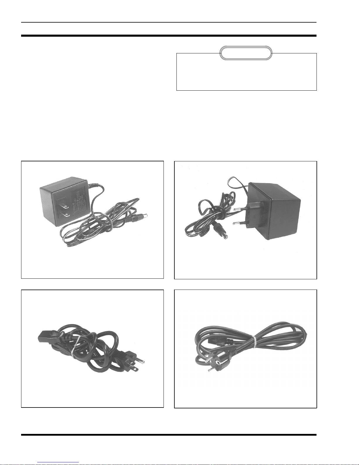
120 Vac Wall Transformer
344A3072P3
120 Vac Wall Transformer
344A3072P10
230 Vac Wall Transformer
344A3072P4
230 Vac Wall Transformer
344A3072P11
6
LBI-38707
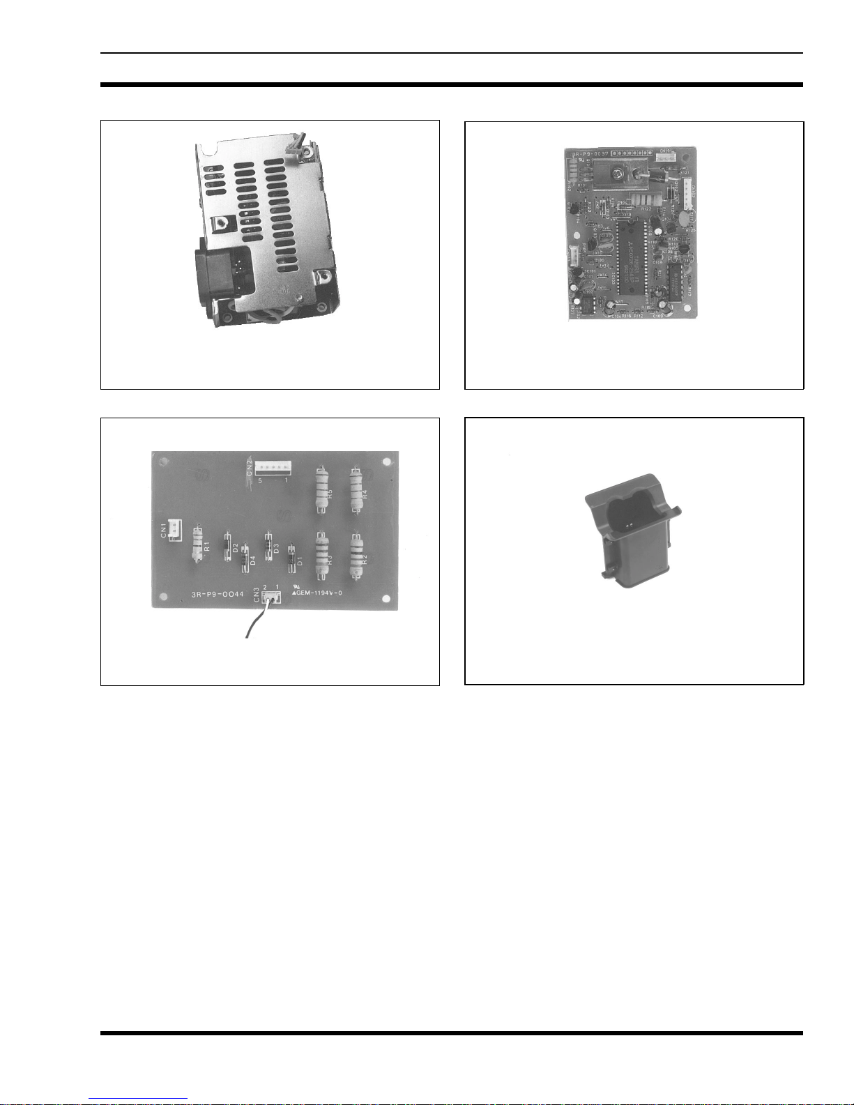
Rapid Charger Powe r S up ply
F29/4R - A9 - 0082
Standard Charger Board
F29/4R - A9 - 0086
INSTALLATION
RAPID DESK CHARGER
Charger on a desk or other flat surface near a 120/230 Vac
50/60 Hz source. Plug the power cord into the charger and
plug the other end into the outlet. (To insure adequate ventilation, allow for a minimum of 1/4" clearance around the top
and bottom covers.)
: Locate the Rapid Desk-
Rapid Charger Control Board
F29/4R - A9 - 0083
Charger Sleeve
M-PA/M-PD 344 A3072P5
PCS 344A3072P6
STANDARD DESK CHARGER
Desk Charger on a de sk or ot her fl at surf ac e ne ar a 120 / 23 0
Vac 50/60 Hz source. Connect the plug end of the power
cable into the power jack located on the rear of the charger.
Plug the "wall cube" power supply end of the power cable
into the outlet. (To insure adequate ventilation, allow for a
minimum of 1/4 " c lea ranc e arou nd th e top an d b otto m cov ers.)
: Locate the Standard
7
 Loading...