

Ericsson LBI-38701 Maintenance Manual

LBI-38701
MAINTENANCE MANUAL
SERVICE SECTION
800 MHZ TRUNKED MOBILE RADIO
TABLE OF CONTENTS
Page
Description............................................................................................................................................ 3
Initial Ad justment................................................................................................................................. 3
Tra nsmitter Adj ustment .. .............................................................................................................. 3
Rec eiver Adjustmen t..................................................................................................................... 3
Re-installation ................................................................................................................................ 3
Preventative Maintenance.................................................................................................................... 3
Connections ................................................................................................................................... 3
Electrical System........................................................................................................................... 3
Mechanical Inspection .................................................................................................................. 3
Antenna .......................................................................................................................................... 3
Alignment....................................................................................................................................... 3
Fre q uency Check........................................................................................................................... 3
Dis assembly Procedures.......... ............................................................................................................. 3
To Remove Top Cover.................................................................................................................. 4
To Remove Bottom Cover............................................................................................................ 4
To Remove The Duplexer Assembly........................................................................................... 4
To Remove The RF Board............................................................................................................ 4
To Remove The Audio Board ...................................................................................................... 5
To Remove The Front Cap Assembly ......................................................................................... 5
To Remove The Logic Board....................................................................................................... 5
To Remove The Duplexer/Interface Board................................................................................. 7
To Remove The System Board .................................................................................................... 7
To Remove The Handset Interface Board........ .. ......................................................................... 7
Chip Component Replacement............................................................................................................ 7
To Remove Chip Components ..................................................................................................... 7
To Replace Chip Components...................................................................................................... 7
Troublesho oting Procedures ................................................................................................................ 8
Self Diagnostics/Error Messages................................................................................................. 8
Test Preparation.................................................................................................................................... 11
Test Mode Commands.......................................................................................................................... 11
Default Conditions ........................................................................................................................ 11
Channel Frequen cy S elect ............................................................................................................ 11
Test Mode Commands and Functions................................................................................................. 11
Single Key Tests............................................................................................................................ 12
Three Key Function Tests............................................................................................................. 14
1

LBI-387 01
TABLE OF CONTENTS
(CONTINUED)
Rad io Alignment Procedure.. ............................................................................................................... 17
Test Equipment And Service Aids............................................................................................... 17
Transmitter Alignmen t.................................................................................................................. 17
Rec eiver Alignment....................................................................................................................... 18
Transm itter Verification................................................................................................................ 19
Rec eiver Verification .................................................................................................................... 20
Diagrams
Audio Signal Flow Diagram......................................................................................................... 21
Control Signal Flow Diagram....................................................................................................... 22
Power Distribution Diagram......................................................................................................... 23
Page
Copyright© March 1992, Ericsson GE Mobile Communications, Inc.
2

LBI-38701
DESCRIPTION
The Service Section contains the information neces-
sary for aligning and troubleshooting the MDR Series
mobile radio. In addition, info rmation is pro v ided for dis assembli ng the radio and replacing c hip c o mpo ne nts.
INITIAL ADJUSTMENT
After the radio has been installe d as described i n the
Installation Manual, the following adjustments should be
made by a certified electronics technician.
TRANSMITTER ADJUSTMENT
The transmitter has been adjusted at the factory and
should require no readjustment. However, the antenna
length should be adjusted for optimum VSWR, and the
freque ncy a nd modul atio n meas ured and recorded for future reference. For the complete transmitter alignment,
refer to the Transmitter Alignment Procedure.
RECEIVER ADJUSTMENT
No initial adjustments to the receiver are required.
Refer to the Receiver Alignmen t Procedure.
ELECTRICAL SYSTEM
Check the vo ltage regulato r and alt ernator or generator per io dically to kee p th e e lectrica l system within safe
and economical operating limits. Overvoltage is indicated
when the battery loses water rapidly. Use of 1 or 2 ounces
of wate r per cell per week is acceptab le for batterie s in
continuous operation. A weak battery will often cause
excessive noise or faulty operation.
MECHANICAL INSPECTION
Since mobile units a re subject to consta nt shock and
vibration, check for loose plugs, nuts, screws a nd other
parts to make s ure that no thing is working loose.
ANTENNA
The antenna, antenna base and all contacts may become coated or poorly grounded; loss of radiation and a
weak signal will result.
ALIGNMENT
The transmitter and receiver meter readings should be
checked periodically, and the alignment "touched up"
when necessa ry . Ref er to the Alignment Procedure in this
manual.
RE-INSTALLATION
The ra dio is des igned to op erate i n 12 volt, negative
ground vehicles only. If the mobile radio is moved to a
different vehic le, alway s che ck t he batt ery po larity of the
new vehicle system.
PREVENTATIVE MAINTENANCE
To ensure high operating efficiency and to prevent
mechanical and electrical failu res from inter rupting system operatio ns, routine check s shoul d be mad e of all mechanical and electric al parts at regula r intervals. Preventive mainten a nce shoul d inclu de t he followi ng che cks.
CONNECTIONS
Ground connections to the voltage source should be
periodically checked for tightness. Loose or poor connections to the power source will cause excessive voltage
drops and faulty operatio n. When ground connections are
not made direct ly to the batte ry, the co nnection from the
battery to vehicle chassis must be checked for low impedance. A high impedance may cause excessive voltage
drops and alternator noise probl ems.
FREQUENCY CHECK
Check transmitter frequency and deviation. Normally,
these checks are made when the unit is first put into
operation, after the first six m onths, and once a year thereafter.
DISASSEMBLY PROCEDURES
Disassembly procedures are provided to completely
disassemble the radio. In general, reassembly is in the
revers e orde r. Inc luded are p roced ures to remo ve t he top
and bottom covers, duplexer, RF board, Audio Board,
Logic Board, Duplexer/Interface Board, System Board,
and Front Cap Assembly inc luding the Hands et/Inte rface
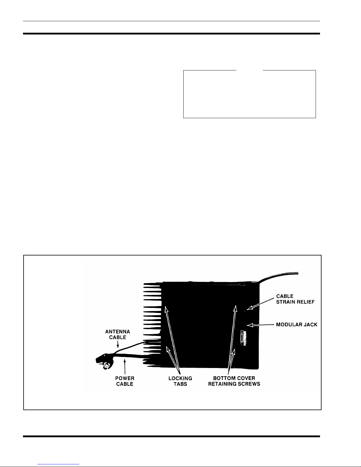
board. Refer to Figure 1, Radio Disassembly.
NOTE
Remove power from the radio before servicing.
3
LBI-387 01
TO REMOVE THE TOP COVER
l. Insert a small standa rd s crewdriver under one side o f the
top cover and gently pry t he side of the c over away from
the frame releasing the locking ta b.
2. Using the screwdri v er, press in on t he ta bs on the r ear of
the radio and release the tw o l ocking tabs.
3. Insert the screwdriver under the other side of the radio
top cover, releasing the remaining locking tab, and remove the cover from the rad io.
TO REMOVE THE BOTTOM COVER
1. Remove the two screws securing the bottom cover to the
radio. (Refer to Figure 1.) The bottom cover can then be
removed from the radio.
TO REMOVE THE DUPLEXER ASSEMBLY
1. Remove the bottom cover of the radio.
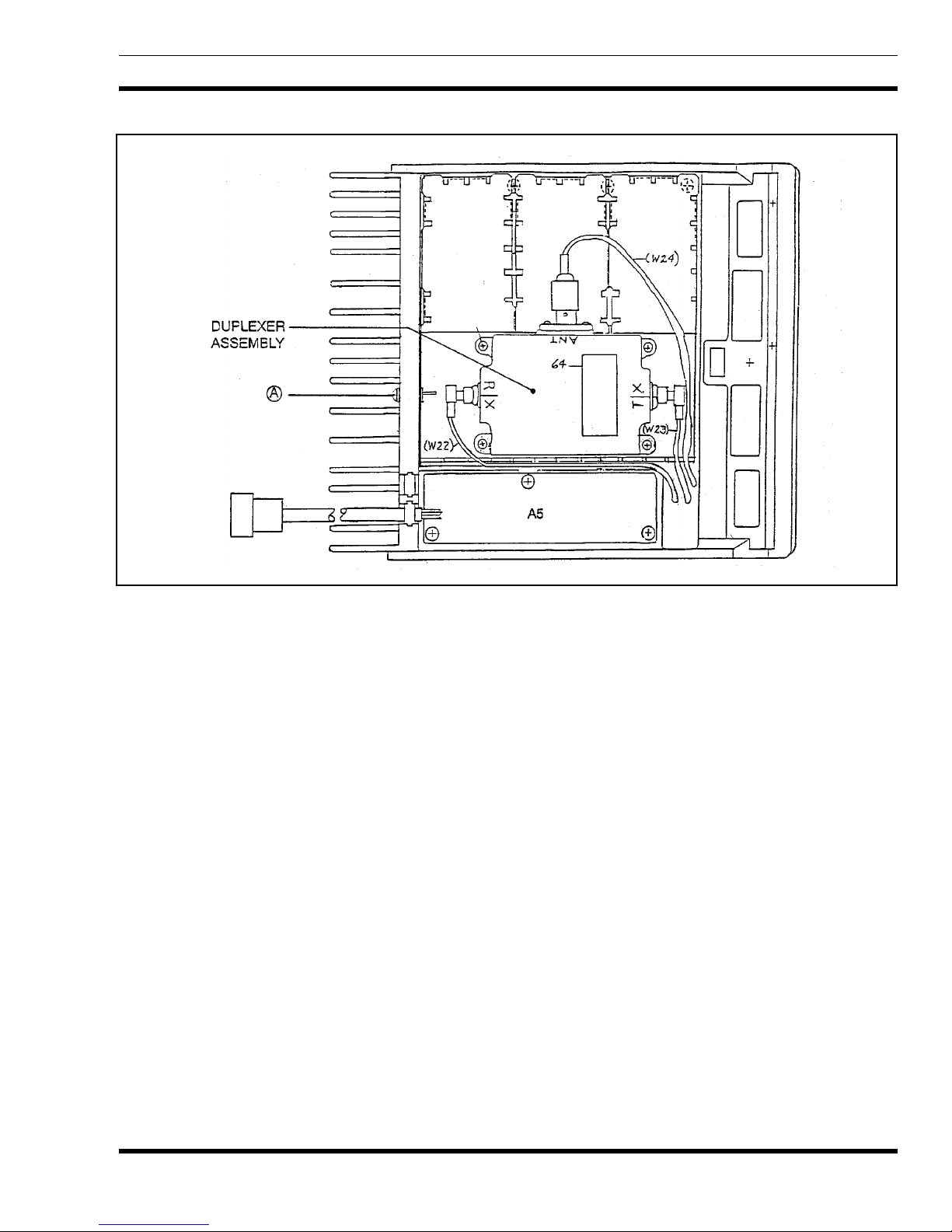
2. Refer to Figure 2. R emove the single M3. 0-0.8 X 20 (#1 0
drive) TORX screw "A", located on th e rear of the radio,
that secur es the dupl exer assembly to the casting.
3. The duplexer can now be removed by disconnecting the
SMB connectors from the TX and RX inputs of the
duplexer and disconnecting the TNC connector from the
ANT port of the duplexer.
NOTE
Servicin g the radio while the du plexer is not proper ly
secured may cause electrical shorts. Special care
must be taken to ensure that the duplexer does not
make contact with any circuitry while power is applied to the radio.
TO REMOVE THE RF BOARD A2
l. Remove the top and bottom covers and the duplexer
assembly from the radio (refer to the procedures above).
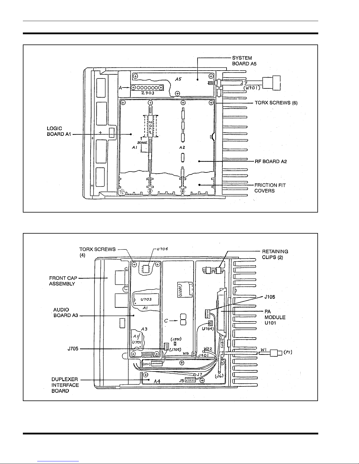
2. Refer to Fig ure 3. Pry off the friction fit covers covering
the RF Board.
3. Using a small standard screwdriver, gently pry the interconnect plug P702 from the Logic and RF Boards
4. Remove the two clips (Figure 4) securing Q101 and U102
to the frame (on top side of board).
5. Remove the t wo M3.5-0.6 x 20 TO RX screws (#15 drive )
securing PA module U101 t o the fra me.
4
Figure 1 Radio Cover Removal
LBI-38701
Figure 2 - Bottom View With Duplexer
6. Remove the six M3.5-0.6 x 8 TORX screws (#15 drive )
from the bottom side of the board.
7. Disconnect wires connected to J105, J704, J705 and the
cables going to the Duplexer Interface Board.
8. Remove the six spring clips protruding through the RF
Board from the bottom side.
9. Gently push the RF board out of the radio casting.
TO REMOVE THE AUDIO BOARD A3
l. Pull out the black clip protruding through the Audio
Board which holds the Logic Board 5-volt regulator
against th e ca sti n g.
2. Refer to Figure 4. Re mov e the four M3. 5-0.6 x 8 TO RX
screws (#15 drive) se curing the Audio Board to the radio.
Pry out the board using a screwdriver in the hole previously occupied by the clip.
TO REMOVE THE FRONT CAP
ASSEMBLY
2. Remove the two M3.5-06 x 8 TORX screws (#15 drive)
from both sides of the front cap and the TORX screw on
the bottom of the fr ont cap.
3. Gently pull the front cap assembly away from the radio
exposing the ribbon cable on the rear of the assembly.
TO REMOVE THE LOGIC BOARD A1
l. Remove the top and bottom c overs, Front Ca p assembly
and the Audio Board from the radio. Refer to the disassembly for each, in this section.
2. Remove interconnect plug P702 from the RF and Logic
Boards on the bottom of the radio.
3. Remove the four M3.5- 0.6 x 8 TORX screws ( #15 drive)
securing the Logic Board to the radio frame.
4. Gently work the Logic Board out of the radio being
careful not to damage the plug going to the Front Cap
Assembly .
l. Remove the top and b ottom covers of the radio.
5
LBI-387 01
Figure 3 - Bottom View Without Duplexer
6
Figure 4 - Top View
CAUTION
LBI-38701
TO REMOVE THE DUPLEXER
INTERFACE BOARD A4
l. Remove the top c over of the radio. Refer to the procedure
above.
2. Disconnect the cables going back to the RF Board.
3. Disconnect the cables from the duplexer.
4. Remove the four M3.5-0.6 TORX screws (#15 drive)
securing the board to the frame. Care full y work the board
out of the radio, unplugging it from the feed through
assembly Z903.
TO REMOVE THE SYSTEM BOARD A5
1. Remove the bottom cover of the radio. Refer to the
procedure above.
2. Disconnect the ribbon cable from J902.
3. Disconnect the option cable if used.
4. Remove the three M3.5-0.6 x 8 TORX screws (#15
drive) securing the board to the frame.
5. Carefully work the b oard out of t he radio, unplugging it
from the feed through assembly Z90 3.
where the compone nt is used (PA module re placement is
located in the RF Board manual ).
Replacement of chip capacitors should always be done
with a temperature controlled soldering iron, operating at
700F (371C). However, DO NOT touch b lack met a l fi l m
of the resistors or the ceramic body of capacitors with the
soldering iron. NOTE: The metallized end terminations of
the parts may be tou ched with the solde ring iron without
causing damage.
The CMOS Integra ted Circuit devices us ed i n this equipment can
be destroyed by static disch arges.
Before symbol handling one of
these devices, the serviceman
should discharge himself by
touching the case of a bench in-
strument that has a 3-pron g power
cord connected to a n outlet with a kn own good earth
ground. When soldering or desoldering a CMOS
device, the soldering iron should also have a 3- prong
power cord connected to an outlet with a known
good earth ground. A battery-operated soldering
iron may be used in place of the regular soldering
iron.
6. Disconn ec t the ribbon cable from the rear of the assembly. The Front Cap Assembly can then be removed from
the radio.
TO REMOVE THE HANDSET
INTERFACE BOARD A9
The Front Cap Assembly contains the Handset Inter-
face Board. Remo ve the Handset Inte rface Board as instructed below.
1. Remove the clip securing the 3 watt PA (U801) to the
front cap casting.
2. Remove the fou r M3.5- 06 x 8 TO RX screws ( #15 dri ve)
securing the board to the front cap casting. Lift the b oard
out of the front cap.
CHIP COMPONENT
REPLACEMENT
The procedure for removing chip components is given
below. Replaceme nt procedures for other unique components ar e locate d in the re lated board instruc tion manual
To Remove Chip Components
l. Using two s old eri n g iro n s sim ultaneously hea t ea ch en d
of the chip until solder flows, and then remove and
discar d th e ch i p.
2. Remove excess solder wi th a vacuum solder extractor.
3. Carefully remove th e e poxy adhesive and excess flux to
preven t da ma ge t o th e pri n t ed board.
To Replace Chip Components
1. Using as little solder as possible, "tin" one end of the
component and one of the pads on the printed wiring
board.
2. Place th e "t inned" en d of the c omponen t on th e "ti nne d "
pad on th e b oar d and simult ane ously tou c h th e c omponent and th e pad with a wel l "tinned" s oldering iron w hile
pressing the component do wn on the board.
7
 Loading...