

Ericsson LBI-38610A FMD Installation Manual
LBI-38610A
Mobile Communications
Installation Manual
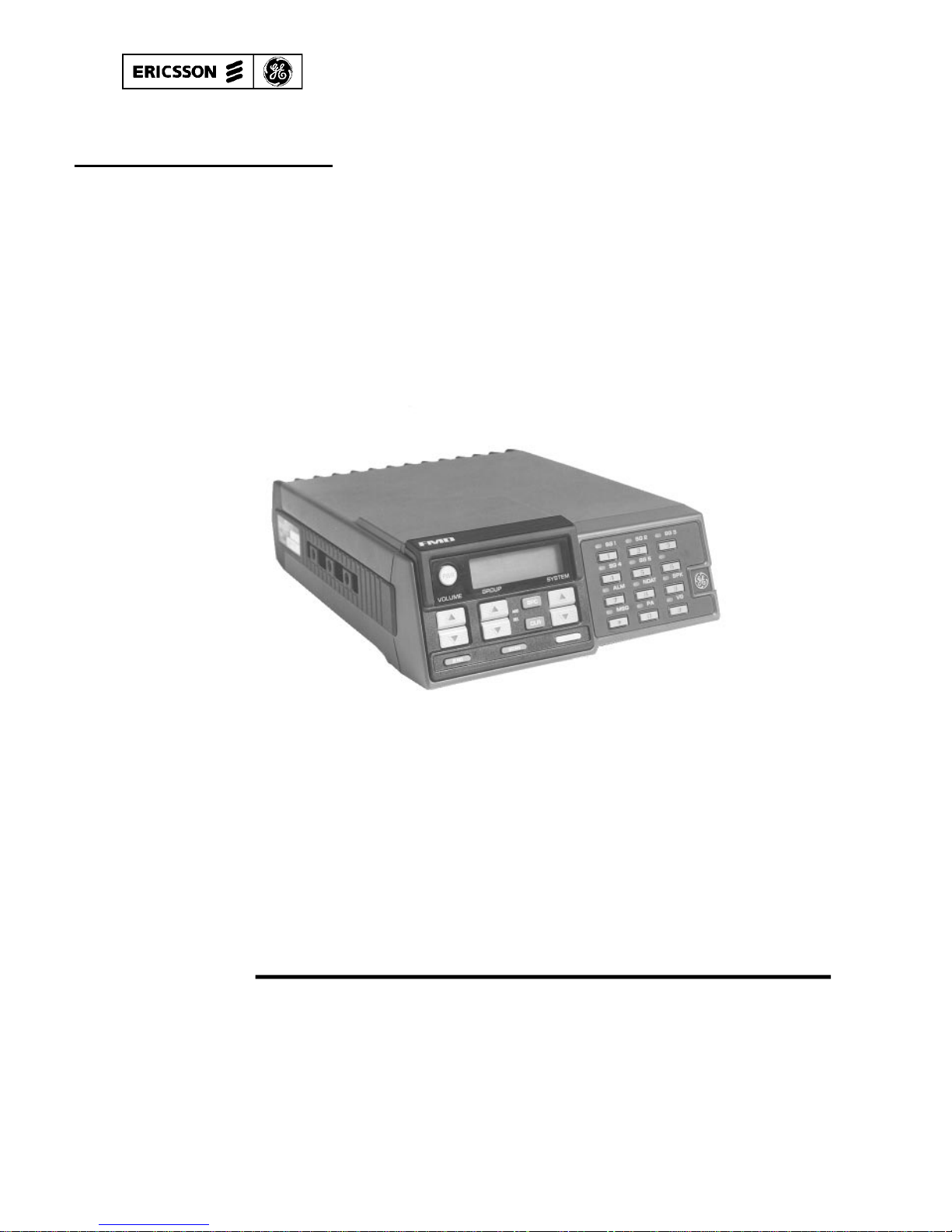
FMD
MOBILE RADIO AND ACCESSORIES

Copyright© August 1991, Ericsson GE Mobile Communications Inc.
TABLE OF CONTENTS
Section/Paragraph . . . . . . . . . . . . . . . . . . . . . . . . . Page
INTRODUCTION . . . . . . . . . . . . . . . . . . . . . . . . . 3
RADIO INSTALLATION . . . . . . . . . . . . . . . . . . . . . 3
UNPACKING AND CHECKING EQUIPMENT . . . . . . 4
PLANNING THE INSTALLATION . . . . . . . . . . . . 4
EQUIPMENT RE QUIRED . . . . . . . . . . . . . . . . . 5
INSTALLATIONS IN VEHICL E S POW ERED B Y
LIQUEFIED (L P) G A S . . . . . . . . . . . . . . . . . . . 5
RADIO CONFIGURATION . . . . . . . . . . . . . . . . . 7
Emergency Switch . . . . . . . . . . . . . . . . . . 8
External And Remote Internal Speakers . . . . . . . 8
Bypass Igni ti on Switch . . . . . . . . . . . . . . . . 9
RUNNING CABLES . . . . . . . . . . . . . . . . . . . . 9
MOUNTING THE RADIO . . . . . . . . . . . . . . . . . 10
POWER CABL E INSTALLATION . . . . . . . . . . . . . 10
MICROPHONE . . . . . . . . . . . . . . . . . . . . . . . . . . 12
ANTENNA . . . . . . . . . . . . . . . . . . . . . . . . . . . . 13
HORN SPEAKER (OPTION) . . . . . . . . . . . . . . . . . . . 13
INSTALLATION . . . . . . . . . . . . . . . . . . . . . . . 14
EMERGENC Y SWITCH MOUNTING . . . . . . . . . . . . . 15
CONNECTION DIAGRAM . . . . . . . . . . . . . . . . . . . 16
2
5. Connect the speaker cable leads and the speaker leads using the two
splice conn ec tors su ppl ied.
6. Provide strain relief for the speaker cable using a standard cable clamp
(not supplied) .
7. Mount the speaker using four 1/4 x 7/8 inch screws and lock washers
supplied.
8. Remove the two s crews holding the cover over the DB-25 connector on
the radi o (c ove r is not m ount e d on all rad ios).
9. Connect the speak er to the DB-25 c onne c tor as shown.
EMERGENCY SWITCH MOUNTING
An optional ext erna l e me r genc y s wi tch ma y be used w i th t he ra dio . After
the switch is mounted, it should be connected to the radio as s hown in Fig-
ure 10.
CONNECTOR COVER
If the MDT connector is not used, place the protective cover (Figure 1)
over the unused connector and tighten the retaining screws. The cover pre-
vents moisture and debris from entering the unused connector. The cover is
shipped mo unt ed to the radio or in the mount in g hardwa re ba g.
INTRODUCTION
This manual conta ins instal la tion instruc ti ons for the FMD Mobile Radio
and associated accessories. Included are mounting and cabling instructions.
Interconne ction and wiring diagrams are provided a t the back of t he m an ua l.
Before installation , the radi o pe rsona lit y shoul d be p rogr amm e d. Refe r to the
applic able pro gra m mi ng ma nua l fo r instructions.
RADIO INSTALLA TIO N
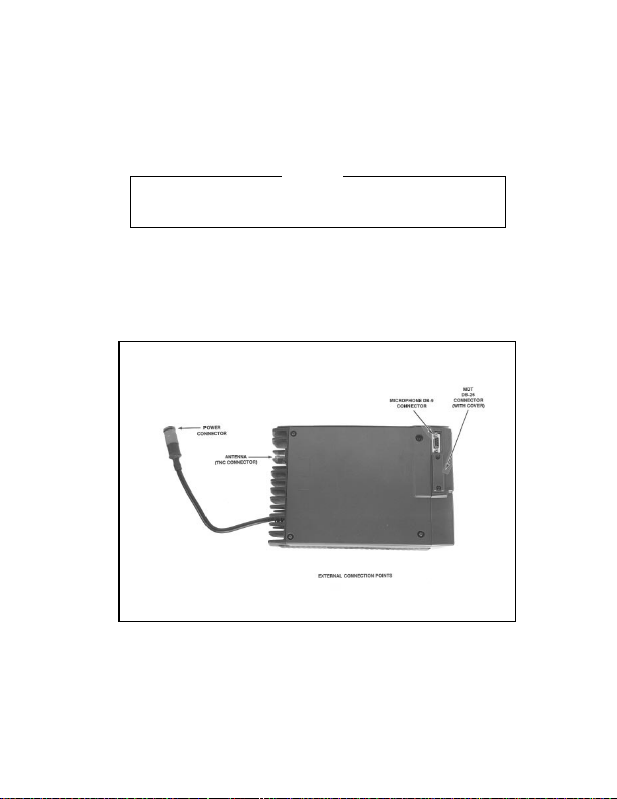
The followi ng para gra ph s will exp lain how to mount and wir e the FMD radio. Insta lla ti on a nd wir ing of exte rna l options a re also cov er ed . Ext er na l
connec tion po ints on the FMD radio are shown i n Figure 1.
The FMD radio is supplied with a test personality. Save this personality with the prog ramm e r befor e ent er ing new cha nne l freque nc ie s.
NOTE
Figure 1 - External Connection Points
3

UNPACKING AND CHECKING EQUIPMENT
When ready for installation, carefully unpack the radio and any accessories. It is recommended that you identify each item in the packing case. If
any damage has occurred to the equipment during shipment, file a claim
with the carrier immediately. The following is a list of equipment packed
with th e ra di o.
* FMD Radio Unit
* Package of moun ting hardware
* Mounting bra c ke t
* Power Cable
* Microp hone
* Microp hone hanger
* Remote int erna l spe ake r (opt io na l with FMD scan m ode l)
* External speaker (optional)
* Emer genc y swit ch (opt ion al)
* Operator’s manual
* Installa ti on m a nua l
PLANNING THE INSTALLATION
Before sta rt ing , pla n your instal la tion c a re ful ly so that it will be :
• Safe for the operator and passengers
• Convenient for t he ope ra tor to use
• Neat
• Protected from wa ter dam ag e
• Easy to service
• Out of the wa y of a uto mecha nics
• Out of the way of passengers
4
ANTENNA
Installation instructions for the antenna are packaged with the antenna.
The antenna mu st be in stalled i n acc ordanc e with goo d e ng ine e ri ng practi ce s
for optimum results.
The most effective mounting position is usually in the center of the roof
of the vehicle. The antenna cable will normally run from the radio, behind
sections of the interior trim to a door or window post. Then run the cable up
between the roof and headliner in the passenger compartment to the antenna
base.
Once the antenna is installed, connected it to the TNC connector at the
left rear of the radio.
HORN SPEAK ER (O PTION)
The horn spe a ke r may be use d as an ex te rna l spea ke r. It may be mounte d un-
der the hood, on the vehicle roof, or other suita ble loc a tion. T he horn
speaker option inc lud es hor n speake r and spea ke r cable assembl y.
Be careful to avoid damaging some vital part (fuel tank, transmission
housing, etc.) of the vehicle when drilling mounting holes. Always
check to see how far the mounting screws will extend below the
mountin g su rfa c e before instal ling.

It is suggested that you take advantage of the experience of one of the
many authorized Service Stations located throughout the United States by
having them install your radio and make the final adjustments. A typical installati on is shown in Figure 2.
EQUIPMENT RE QUIRED
The equipm ent requ ire d for inst alli ng the radio and ac cessori es is liste d
belo w :
• Electri c dril l fo r drilling mou nti ng h o le s
• Drills (see sizes in box)
• Phillips screwdri ve r a nd Al len wre nc h for mounting scr ews
• Electrical Tape
INSTALLATIONS IN VEHICL E S POWE RED BY L IQUE FIE D (LP) G AS
Interference with vehicular electronics - Electronic fuel injection
systems, ele ctron ic anti-ski d bra kin g system s, elect ron ic cruise c ontrol systems, etc. are typical of the types of elec tro nic de vice s which
may be prone to malfunction due to the lack of protection from radio frequency energy present when transmitting. If the vehicle contains such equipment, consult the dealer for the make of vehicle for
help in determining if such electronic circuits will perform normall y w he n the radi o is tr ansmitt ing.
WARNING
• No. 36 (7/64-inch) drill for No. 6 self-tapping screw
• No. 31(1/8-inch) drill for No. 8 self-tapp ing scre w s
• No. 27 (9/64-inc h) dril l fo r No. 10 self-t ap ping screws
• No. 9 (3/16-inc h) dr ill for No. 9 self- tapping screw s
DRILL SIZES
Radio installation in vehicles powered by liquefied petroleum gas
must confor m to the follo wing req uir eme nt s.
WARNING
5
 Loading...