

Page 1

LBI-38378D
Maintenance Manual
M-PA
VHF
PORTABLE FM RADIO
ERICSSONZ
TABLE OF CONTENTS
REAR COVER ASSEMBLY . . . . . . . LBI-38597
FRONT CO VE R ASSEMBLY (EARLIER)
AND CONTROL BOARD . . . . . . . . LBI-38384
FRONT CO VE R ASSEMBLY (LAT ER)
LESS CONTROL BOARD . . . . . . . . LBI-38834
CONTROL BOARD (LATER) . . . . . . LBI-38828
VHF SERVICE SECTION . . . . . . . . LBI-38385
Page 2

LBI-38378D
TABLE OF CONTENTS
SPECIFICATIONS . . . . . . . . . . . . . . . . . . . . . . . . . . . . . . . . . . . . . . . . . . . . . . . . . . 3
OPTIONS AND ACCESSORIES . . . . . . . . . . . . . . . . . . . . . . . . . . . . . . . . . . . . . . . . . . 4
INTRODUCTION . . . . . . . . . . . . . . . . . . . . . . . . . . . . . . . . . . . . . . . . . . . . . . . . . . 5
FEATURES . . . . . . . . . . . . . . . . . . . . . . . . . . . . . . . . . . . . . . . . . . . . . . . . . . . 5
DESCRIPTION . . . . . . . . . . . . . . . . . . . . . . . . . . . . . . . . . . . . . . . . . . . . . . . . . . . . 6
REAR COVER ASSEMBLY . . . . . . . . . . . . . . . . . . . . . . . . . . . . . . . . . . . . . . . . . . 8
FRONT COVER ASSEMBLY . . . . . . . . . . . . . . . . . . . . . . . . . . . . . . . . . . . . . . . . . 8
ANTENNAS . . . . . . . . . . . . . . . . . . . . . . . . . . . . . . . . . . . . . . . . . . . . . . . . . . . 8
BATTERY PACKS . . . . . . . . . . . . . . . . . . . . . . . . . . . . . . . . . . . . . . . . . . . . . . . 8
UNIVERSAL DEVICE CONNECTOR . . . . . . . . . . . . . . . . . . . . . . . . . . . . . . . . . . . . 9
PROGRAMMING
FEATURES PROGRAMMABLE ON A PE R CHANNE L BASIS . . . . . . . . . . . . . . . . . . . . . . 9
FEATURES PROGRAMMABLE ON A PER MODE BASIS . . . . . . . . . . . . . . . . . . . . . . . . 9
FEATURES PROGRAMMABLE ON AN OVERALL RADIO BASIS . . . . . . . . . . . . . . . . . . . 9
OPERATOR MANUAL . . . . . . . . . . . . . . . . . . . . . . . . . . . . . . . . . . . . . . . . . . . . . . . 11
OPERATING TIPS . . . . . . . . . . . . . . . . . . . . . . . . . . . . . . . . . . . . . . . . . . . . . . . . . . 11
INTRINSICALLY SAFE USAGE . . . . . . . . . . . . . . . . . . . . . . . . . . . . . . . . . . . . . . . . . . 11
BATTERY PACKS . . . . . . . . . . . . . . . . . . . . . . . . . . . . . . . . . . . . . . . . . . . . . . . 11
ACCESSORIES . . . . . . . . . . . . . . . . . . . . . . . . . . . . . . . . . . . . . . . . . . . . . . . . . 11
MAINTENANCE . . . . . . . . . . . . . . . . . . . . . . . . . . . . . . . . . . . . . . . . . . . . . . . . . . 12
PREVENTIVE MAINTENANCE . . . . . . . . . . . . . . . . . . . . . . . . . . . . . . . . . . . . . . . 12
DISASSEMBLY/ REASSEMBLY . . . . . . . . . . . . . . . . . . . . . . . . . . . . . . . . . . . . . . . 13
ILLUSTRATIONS
Figure 1 - System Model . . . . . . . . . . . . . . . . . . . . . . . . . . . . . . . . . . . . . . . . . . . . 7
Figure 2 - Scan Model . . . . . . . . . . . . . . . . . . . . . . . . . . . . . . . . . . . . . . . . . . . . . . 7
Figure 3 - Select Model . . . . . . . . . . . . . . . . . . . . . . . . . . . . . . . . . . . . . . . . . . . . . 7
Figure 4 - Side Vie w (All Models) . . . . . . . . . . . . . . . . . . . . . . . . . . . . . . . . . . . . . . . 7
Figure 5 - UDC Pin-Out . . . . . . . . . . . . . . . . . . . . . . . . . . . . . . . . . . . . . . . . . . . . . 10
Figure 6 . . . . . . . . . . . . . . . . . . . . . . . . . . . . . . . . . . . . . . . . . . . . . . . . . . . . . 13
Figures 7, 8 - Disassembly/Reassembly Diagrams . . . . . . . . . . . . . . . . . . . . . . . . . . . . . . . 14
Figures 9, 10 - Disassembly/Reassembly Diagrams . . . . . . . . . . . . . . . . . . . . . . . . . . . . . . 15
Figure 11 - Rear Cover Assembly Block Diagram . . . . . . . . . . . . . . . . . . . . . . . . . . . . . . . 16
Figure 12 - Front Cover Assembly (Earlier) And Control Board Block Diagram . . . . . . . . . . . . . . . 17
Table 1 -VHF Antennas . . . . . . . . . . . . . . . . . . . . . . . . . . . . . . . . . . . . . . . . . . . . . 8
Table 2 - UDC Pin Functions . . . . . . . . . . . . . . . . . . . . . . . . . . . . . . . . . . . . . . . . . . 10
Table 3 - Torque Specifications . . . . . . . . . . . . . . . . . . . . . . . . . . . . . . . . . . . . . . . . . 13
Page
NOTICE
This manual covers Ericsson and General Electric products manufactured and sold by Ericsson Inc.
NOTICE
Repairs to this equipment should be made only by an authorized service technician or facility designated by the supplier.
Any repairs, alterations or substitution of recommended parts made by the user to this equipment not approved by the
manufacturer could void the user’ s authority to operate the equipment in addition to the manufacturer’ s war ranty.
NOTE
The software contained in this device is copyrighted by Ericsson Inc. Unpublished rights are reserved under the copyright laws of the United States.
This manual is published by Ericsson Inc., without any warranty. Improvements and changes to this manual necessitated by typographical errors , inaccuracies of current information, or improvements to
programs and/or equipment, may be made by Ericsson Inc., at any time and without notice. Such changes will be incorporated into new editions of this manual. No part of this manual may be reproduced
or transmitted in any form or by any means, electronic or mechanical, including photocopying and recording, for any purpose, without the express written permission of Ericsson Inc.
Copyright© November 1989, General Electr ic Company
2
Page 3

SPECIFICATIONS*
GENERAL
Frequency Bands FCC TYPE DOC
146 - 162 MHz AXATR-182-B5 TR-182-D2
157 - 174 MHz AXATR-182-C5 TR-182-D2
136 - 150.8 MHz
Frequency Stability 5.0 ppm
Channel Capacity
Select Model 16
Scan Model 192
System Model 192
Maximum Frequency Separation full bandsplit
Channel Spacing 30 kHz
Operating Temperature Range -30°C to +60°C
Maximum Relative Humidity 90% at 55°C
LBI-38378D
Battery Voltage 7.5 Vdc (nominal)
Dimensions (H x W x D)
less battery, knobs and antenna 140 x 69 x 38 mm (5.52 x 2.72 x 1.50")
with Extra High Cap. Battery 232 x 69 x 40 mm (9.15 x 2.72 x 1.58")
Weight
less battery and antenna 540 grams (19 ounces)
with Extra High Cap. Battery 907 grams (32 ounces)
TRANSMITTER
Rated RF Power Output 6.0 Watts
High / Low RF Power Output 6.0 Watts / 1 Watt (programmable per channel)
Maximum FM Deviation ±5 kHz
FM Hum and Noise -45dB (companion receiver)
Spurious and Harmonic Emissions -75 dBc
Audio Response +1 to -3dB (6 dB/oc tave pre-emphasis from 300 Hz to 3 kHz)
Audio Distortion less than 3% (at 1000 Hz tone, 3 kHz deviation)
RECEIVER
Sensitivity (12 dB SINAD) -116 dBm (0.35 µV)
Adjacent Channel Selectivity -80dB
Critical Squelch 10dB SINAD
Intermodulation -78dB
Spurious and Image Rejection -80dB
Audio Output 500 mW (24-ohm load impedance)
Audio Response +2 to -8dB (6 dB/octave de-emphasis from 300 Hz to 3 kHz)
Audio Distortion less than 5% (at 500 mW)
* These specifications are intended primarily for the use of the serviceman. See the appropriate Specifications Sheet for
the complete specifications.
3
Page 4
LBI-38378D
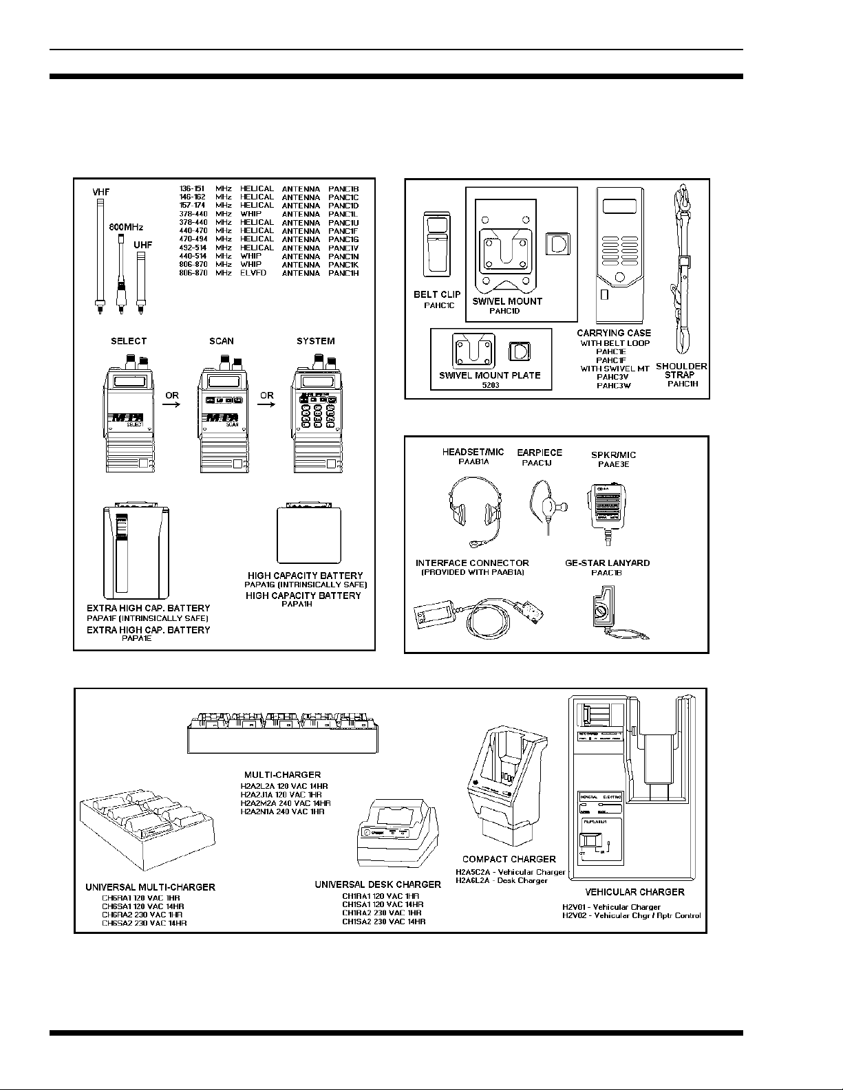
OPTIONS AND ACCESSO RIES
Radios, Antennas, Batteries
Carrying Accessories
A udio Accessories
Chargers
4
Page 5

LBI-38378D
INTRODUCTION
The M-PA radi o is a high quality microprocessor con-
trolled synthesized portable FM radio. M-PA operation is
highlighted by the rad io’s programming versatility. This allows tailored operation of the portable radio to meet the
needs of the radio system and the individual users. Three ( 3)
different M-PA radio models are available: Select, Scan and
System.
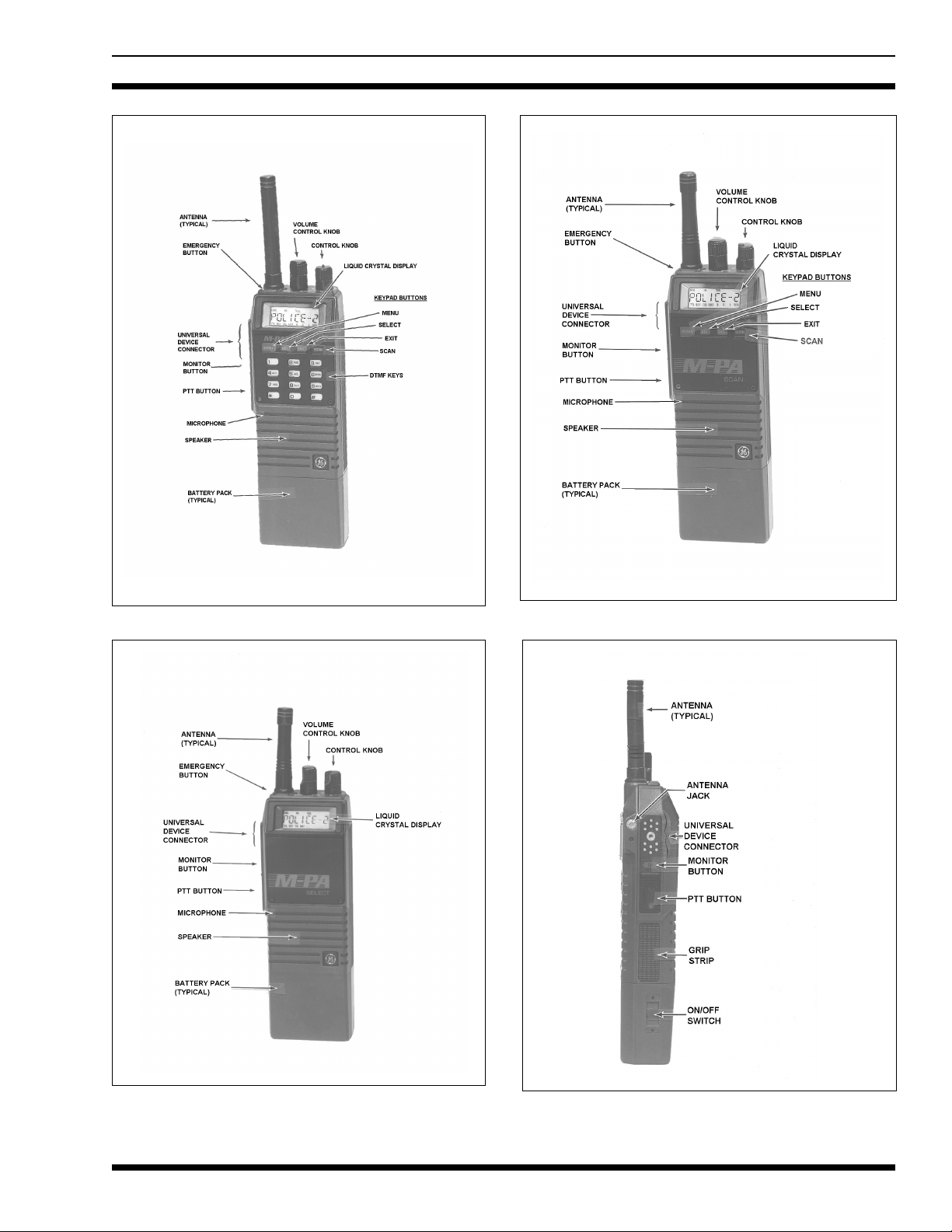
The M-PA S elect model radio is the basic version that
can be programmed with up to sixteen (16) channels. This
unit features an 8-digit alphanumeric liquid crystal display
(LCD) and a 16-position knob for channel selection. The
display is backlit for nighttime and low-level ambient light
operation.
Scan and System model radios have an LCD similar to
the Select model radio. A keypad is ad ded to these radios (4button on Scan model, 16-button on System model) to provide additional features not available on the Select model
radio. These radios can be programmed with up to 192 different radio channels. Bot h also provide scan cap ability including dual-priority scan, and DTMF telephone
interconnect of up to ten (10) preprogrammed numbers. The
telephone numbers can be recalled at will and initiated. The
System model’s numeric keypad allows editing of the ten
preprogrammed numbers and manual DTMF telephone inter-connect dialing.
FEATURES
192-Channel Capability
•
radios can be programmed with up to 192 channels
accessed in 12 modes (banks of channels) with 16
channels in each mode or 16 modes with 12 channels
in each mode. The Select model radio can be
programmed with a maximum of 16 channels.
Backlit Liquid Crystal Display
•
alphanumeric LCD provides programmable
custom i zat io n an d feed ba ck to t h e op er at o r of vari ou s
operating conditions. Status flags located above and
below the digits alert the operator to various radio
conditions such as channel busy, transmitter in
operation, or a low battery condition. Scan and
System model radios have additional status flags for
scan operation. LCD backlighting can be enabled or
disabled on a per channel basis.
Rotary Control Knob
•
radios, the 16-position top-mounted Control Knob
allows easy selection of modes (banks of channels),
channels or Channel Guard (CG) according to how
the radio is programmed. On the Select model radio,
the Control Knob selects the operating channel. A
stop-plate may be installed under the knob to limit the
- Scan and System models
- The 8-digit
- On Scan and System model
maximum number of positions to less than sixteen
(16). It is normally factory installed for fifteen (15)
positions.
Volume Control Knob
•
provides quick and easy adjustments to the volume
level. Minimum volume levels can be programmed
into the unit. This feature prevents missed calls due to
a low volume setting.
Monitor Button
•
to disabled squelch and if programmed for the
selected channel, it is used to toggle CG and/or T99
operation on and off.
Keypad
•
keypad on its front panel that provides scan and menu
control. The menus allow selection of the current
operating mode (bank of channels) and/or channel
depending upon the radio’s programming. The menus
also allow control of various other radio features such
as selection of stored telephone interconnect numbers
for auto-dial operation, and alert tone enable/disable
control. A System model radio has a 16-button
keypad. The top four (4) buttons are identical to the
Scan model keypad, providing scan and menu
control. The lower twelve (12) buttons form a
numeric keypad that allows manual DTMF telephone
interconnect dialing and editing of telephone
interconnect numbers stored in the radio. Select
model radios do not have a keypad.
Scan Capability
•
be programmed for non-priority scan or dual-priority
scan operation. Scan programming options include a
keypad entered scan list or a fixed scan list. Priority
scan programming options include a fixed
priority-one channel or the selected channel as the
priority-one channel. The radio c an be p rogr amme d to
scan on ly the channels in the curr ent mode (bank of
channels) or it may be programmed to scan across
modes. The S elect model radio do es not support scan
operation.
Telephone Interconnect Capability
•
System model radios can store up to ten (10)
telephone interconnect numbers for auto-dial
operation. These numbers are preprogrammed into
the Scan model radio. In the System model radio, the
numbers can be preprogrammed, operator-entered
and/or edited via the numeric keypad. The System
model’s numeric keypad also allows manual DTMF
tele phone interconnect dialing. The Select model
radio cannot initiate telephone interconnect calls.
- The Scan model radio has a 4-button
- This side-mounted button is used
- Scan and System model radios can
- This rotatable control
- The Scan and
5
Page 6

LBI-38378D
• Programmable Multi-Tone Channel Guard
(CTCSS) - Channel Guard tone frequencies within
the range of 67 H z to 210.7 Hz, including all of the
standard EIA frequencies, can be programmed for
encoded/de coded operation.
• Programmable Multi-Code Digital Channel
Guard - Similar capability as with tone Channel
Guard is provided.
• Two-Tone Sequential (T99) Decode - Selective
calling decode is enabled or disabled on each
individual channel. Two (2) sets of unique de-codes
are programmable to allow large systems individual
and group call capability. Sets are selectable on a
mode (bank of channels) basis.
• Channel Busy Lockout - Personality information
includes transmit disable capability on a channel
where carrier activity is present This feature is
selectable o n a per channel basis.
• GE-STAR Compatibility - The radio can be
programmed to transmit GE-STAR at PTT key, at
PTT unkey, or both. 16,384 individual ID codes are
available.
• Emergency Signalling Feature - GE-STAR
emergency signalling can be enabled by the red
Emergency/Home Button on the top of the radio or it
can be enabled by a lanyard connected to the UDC.
• Home Button - The radio can be programmed to
switch to a home mode or channel (depending on
Control Knob’s programming) when the red
Emergency/Home Button on the top of the radio is
pressed.
• Programmable Carrier Control Timer - A
programmable transmit timer will automatically
disable the transmitter and provide an alerting tone
after time-out. This feature prevents radio damage and
unnecessary channel traffic in the event of a "stuck"
mic. The CCT is reset on every PTT.
• Programmable Transmit P ower Le v el - Transmitter
power level is PC programmable into the radio (high
or low) on a per channe l basis.
• Squelch Tail Elimination - Squelch and audio
circuits are designed so that annoying squelch pops
which may occur at the end of received messages are
minimized. This feature is compatible with existing
STE systems.
• Alert Tones - Alert tones prompt the operator of
various radio conditions such as key pressed, CCT
time-out or a low battery.
• Power-Up Self-Test - At power-up the radio
automatically performs a diagnostic test on itself and
reports any found error s via the LCD.
• Programmable via the Universal Device Connector
(UDC) - The entire operation of the radio can be field
customized by programming the unit using an IBM
PC or compatible computer. The programmed
personality is stored in nonvolatile memory within the
radio.
• Simple Remote Control Capability - External
accessories can be connected to the UDC such as a
headset, a speaker-mic or a lanyard. Connection of
the speaker-mic allows the operator to remotely
control PTT operation and audio level of the external
speaker. An antenna jack is located on the UDC for
the connection of a remote mounted antenna such as
when the radio is used in a vehicula r ch arger.
• Meets MI L-810C and D Specifications - The sturdy
die-cast aluminum case is designed to seal out
moisture, blowing rain and other harsh environmental
factors.
• Ba ttery Packs - Several different battery pack sizes
and capacities are available.
• Available Options - These options include the
antennas, audio accessories, batteries, carrying
accessories, chargers, lanyards, and the vehicular
chargers.
DESCRIPTION
Two major asse mblies form an M-PA radio. The Front
Cover Assembly contains all of the microproce ssor circ uitry,
audio circuitry and the operating controls. The Rear Cover
Assembly houses the RF circuitry which includes the transmitter, receiver and the frequency synthesizer. The assemblies are electrically interconnected by two single-in-line
type connectors. When mated together, the assemblies form
a weather resistant diecast aluminum case that protects the
radio’s circuitry from harsh outside environments.
Power is provided by a battery pack that slides and
locks on to the bottom of the radio. The radio’s on/off
switch is located on the battery pack.
The antenna screws on to the top of the unit A side antenna connection is also provided at the UDC for an ex ter nal
antenna or for test purposes. This UDC antenna connection
is also utilized for external antenna operation when the radio
is locked in the vehicular charger.
6
Page 7
LBI-38378D
Figure 1 - System Model
Figure 2 - Scan Model
Figure 3 - Select Model
Figure 4 - Side View (All Models)
7
Page 8

LBI-38378D
REAR CO VER ASSEMBLY
The Rear Cover Assembly houses the RF Board in the
die-cast aluminum case. The complete assembly consists of
the VHF RF Board, aluminum case, top antenna jack, side
(UDC) antenna jack and various hardware.
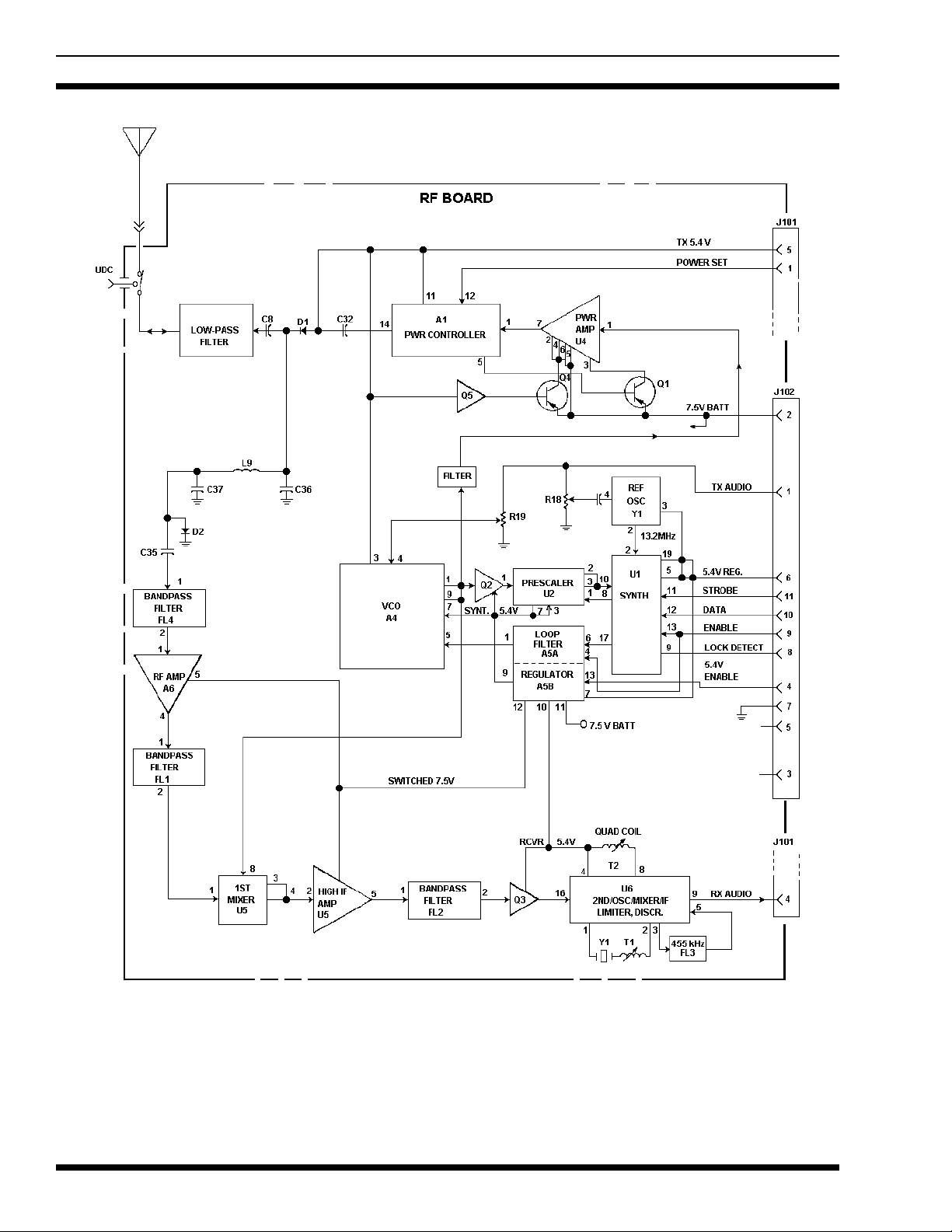
The RF Board’s circuitry includes the transmitter, receiver and the frequency synthesizer. This FM circuitry is
under complete control of the microprocessor circuits. Controlling data sent to this assembly from the Control Board
includes serial s yn thes izer d ata load ing, transmitter/receiver
enabling and a transmitter power le ve l signal. The RF B oa rd
outputs the demodulated audio and a synthesizer lock status
line to the Control Board. During transmitter operation, the
RF power appears at the top antenna jack (or the UDC jack
if the appropriate adapter plug is inserted). The Rear Cover
Assembly maintenance manual contains a detailed circuit
analysis, mechanical, outline and schematic diagrams for
this assembly.
FRONT COVER ASSEMBL Y
The Front Cover Assembly houses all of the operating
controls and the digital control circuitry for the radio. Board
assemblies used in this assembly include the Control and
LCD Boards and flex circuits include the Keypad, UDC and
Speaker Flex circuits. The speaker, microphone and Battery
Plate are also a part of this assembly. The complete assembly is housed in the die-cast aluminum front cover. Sc an and
System model radios are equipped with a keypad on the
front panel.
The Control Board located in the Front Cover Assembly
is the largest and most complex board in the Front Cover
Assemb ly. It conta in s all m icr oc ompu ter an d audio circ uitry
which controls the radio. See the maintenance manuals specific to the Control Board or the Front Cover Assembly for
service information on the related assembly.
ANTENNAS
Antennas are selected based on the operating frequency
range of the radio. T a ble 1 lists the available ante nnas which
mount in the antenna jack on the top of the radio. An exter-
T A BLE 1 -VH F ANTENN AS
nal antenna can be mounted to the unit via the UDC. When
an antenna is connected to the UDC, the antenna on the top
of the radio is disabled.
BATTERY PACKS
The battery pack connects to the bottom of the unit and
delivers a nominal 7.5 Volts dc to the radio. A recessed
on/off switch for the radio is locat e d on th e battery pack. An
internal fuse located in the radio’s Battery Plate protects the
radio and battery from excessive current draw. The battery
packs are available in several different capacities and sizes.
Radio contacts located on the top of the pack include
switched power , ground, the speaker enabling con tac ts a nd a
continuous power contact In addition, four contacts are located on the rear of the battery pack. These four contacts
provide connections to the slip-in type chargers or vehicular
chargers/repeaters while th e battery pack is still connected
to the unit The battery charging contacts are diode pro t ec t ed
from external shorts.
The chargers utilize an internal thermistor in the battery
pack to sense temperature and automatically control charge
rate of the battery. This allows for a maximum charge rate
without overheating the battery pack. All battery packs can
be charged in less than 1 1/2 hours with the rapid type
chargers. Nominal full charge time in a standard charger is
14 hours. The Service Section contains a detailed outline
and schematic diagram of a typical battery pack. Further
service information for the battery packs is also presented in
the Service Section.
Chargers are availab l e with no minal ch arge times of one
hour (rapid) and fourteen hours (standard). Combinations
include singl e (1) and multi (5 or 6) position, standard and
rapid charge units. In addition, t he v ehi cular ch argers simultaneously charge the battery while the radio is operating.
The battery packs should be fully charged in an appropriate charger before they are placed into service. This applies to new battery packs received from the factory and to
battery packs that have been stored for long periods of time.
A fully charged battery pack should have an open-terminal
voltage greater than 7.5 Volts (typically 9.0 Vdc). A battery
USABLE FREQ.
RANGE (MHz)
136-151 PANC1B 19B234804P1 Helical Brown
146-162 PANC1C 19B234804P2 Helical Red
157 - 174 PANC1D 19B23480 4P 3 Helical Orange
8
OPTION
NUMBER PART NUMBER TYPE
COLOR
BANDS
Page 9

LBI-38378D
pack in need of a charge will cause the low battery "BAT"
status flag on the radio to turn on. This flag will turn on
when the battery pack’s voltage drops below approximately
6.8 Volts. The low battery alert tone will also be he ard when
the battery pa ck needs charging.
RECHARGEABLE BATTERY PACK
DISPOSAL
The product that you ha ve purchased contains a r echargeable battery. The battery is recyclable. At
the end of its useful life, under various state and
local laws, it may be illegal to dispose of this battery into the municipal waste stream. Check with your local
solid waste officials for details in your area for recycling options o r proper disposal. Call Toll Free 1-800-8-BATTERY
for information and /or procedures for returning rechargeable batteries in your state.
UNIVERSAL DEVICE CONNECTOR
The UDC is located on the side of radio just above the
PTT and Monitor Buttons. Various equipment such as the
audio accessories can be connected to the radio via the
UDC. The programming equipment is also connected to it
when the personality is programmed into the radio. The
UDC furnishes an excellent first-check-point for initial
bench checks without the need to disassemble the radio. Table 2 lists all pins and their appropriate function. When the
radio is turned on it senses the resistance value between
UDC pins 9 and 1 and switches the appropriate circuits to
provide proper radio-to-accessory operation.
FEATURES PROGRAMMABLE ON A PER
CHANNEL BASIS
• Transmit and Receive Freq ue nc ies
• 8-Character Alphanumeric Display (Channel
Designator)
• Tone or Digital Channel Guard Encode/Decode
• Type 99 Tone Decode En ab led or Di sa b led
• Transmit Power Level High or Low
• Transmit STE On or Off
• Channel Busy Lockout Enabled or Disabled
• Carrier Control Timer
• Backlig ht O n or Off
• Alert Tones On or Off
• Switch Crystal Frequency Enabled or Disabled
• GE-STAR Enabled or Disabled
• GE-STAR sent with Channel Guard
• Channel on Default/Fixed Scan List*
FEATURES PROGRAMMABLE ON A PER
MODE BASIS*
• Channel Data
• 8-Character Alphanumeric Display (Mode
Designator)
• Type 99 Grou p S et S el e ct i o n ( O ne or Two)
PROGRAMMING
The radio’s personality is programmed using an IBM
PC or compatible computer. A full-screen portable PC can
be used for field programming. The Programming Manual
and Software is TQ-3339 and TQ-4339. TQ-3339 is supplied with 5-1/4 inch floppy disks and TQ-4339 is supplied
with 3-1/2 inch disks. This software uses a series of screens
and windows to guide you through a programming session.
See TQ-3339 or TQ-4339 for further programming details.
PC Programming Adapter TQ-3370 and Programming Cable TQ-3311 will also be required. These items provide interface and connection between the PC and the radio when
the personality is transferred from the PC into the radio.
NOTE
After programming or reprogramming the radio, disconnect the programming cable and turn the radio off
and then back on. This action will take the radio out of
programming mod e an d re s t or e no rm al op er at i o n.
• Priority-One and Priority-Two Scan Channels
• DT MF Enabled or Disabled
• GE-STAR Channel
• Home Channel
FEATURES PROGRAMMABLE ON AN
OVERALL RADIO BASIS
• Minimum Volume Level
• Power-Up Beep On or Off
• Transmit Backlight On or Off
• Backlight On or Off when in Vehicular Charger
• GE-STAR And GE-STAR Emergency Options
9
Page 10

LBI-38378D
TABLE 2 - UDC PIN FUNCTIONS
PIN NAME INPUT OR
OUTPUT
1 GROUND ------- Case Ground
3 UDC RX AUDIO Output T est Point For Speaker Audio
4 SWBATT Output Switched Accessory Powe r
5 EXT PTT Input External Microphone PTT Input
6 TX DATA Input For Programming
7 RX DATA Output For Programming
8SPARE
9 UDC VOL T ------- Option/Accessory Sense Pin
10 T/R Output Low = Transmit, High = Receive
11 UDC MUTE Output Low = Audio Muted
12 EXT MIC HI Input External Microphone Audio Input
13 EXT EMER Input Lanyard Connection
34 UDC DISCR Output T est Poin t For RX Aud io
USE
10
Figure 5 - UDC Pin-Out
Page 11

LBI-38378D
• Two individual Type 99 Tone Group Sets
• Control Knob selects Channels, Modes or Channel
Guard*
• Menu Selections*
• Home Mode or Home Channel (depending on
Control Knob programming) or Disabled*
• Scan Enabled or Disabled*
• Scan with Channel Guard Enabled or Disabled*
• Scan Across Modes Enabled or Disabled*
• P riority-One Scan Channel is the Selected Channel,
Fixed Channel or Keypad Entered Channel*
• Ten (10) Telephone Numbers and Names*
• DTMF Options*
* Scan and System models only
OPERATOR MANUAL
Complete operating details for the M-PA radios are included in LBI-38377. This operator’s manual contains detailed operating procedures for the Select, Scan and System
model radios.
INTRINSICALLY SAFE USAGE
Selected portable radios with appropriate factory installed F4 Opt ions are certified as Intrinsically Safe by the
Factory Mutual Research Corporation. Intrinsically Safe approval includes Class I, II, III, Division 1 hazardous locations in the presence of Groups C, D, E, F and G
atmospheres. Non-Incendive approval includes Class I, Division 2 hazardous locations in the prese nc e of Groups A, B,
C and D atmospheres.
Hazardous locations are defined in the National Electrical Code. Useful standards NFPA 437A and NFPA 437M
for the classifications of hazardous areas can be ordered
from the National Fire Protection Ass ociation, Ba tterym arc h
Park, Quinc y, MA 02269.
BATTERY PACKS
Only battery packs identified with a green latch shall be
used with a portable radio that is rated and labeled as Factory Mutual Intr insically Safe. Use of non-specified battery
packs voids Factory Mutual approval. The following battery
pack options are approved for use in intrinsically safe radios:
PAPA1F Rechargeable Battery Pack,
Extra High Capacity (Tall Case)
OPERATING TIPS
Antenna location and condition is important when using
a VHF radio. Operating the radio in low areas of terrain, under power lines or bridges, inside of a vehicle or in a metal
or steel framed building can se v erely reduce the range of the
unit Mountains and buildings can also reduce the range of
the unit.
In areas where transmission or reception is p oor, some
improvement maybe obtained by insuring that the antenna i s
vertical. Moving a few yards in another direction or moving
to a higher elevation may also improve communication. Vehicular operation can be aided with the use of an externally
mounted antenna.
Battery condition is ano ther critical factor in the trouble
free operation of a portable radio. Observe the procedures
listed in the Service Section to insure the battery packs do
not develop the "Memory Effect".
Always observe all of the Federal Communication
Commission’s rules and regulations during any service or
operating proc ed ur e.
PAPA1G Rechargeable Battery Pack,
High Capacity (Short Case )
A CCESSORIES
The accessories that follow are approved for us e with
intri ns ic all y sa fe ra di os . Us e of acces sori es ot her th an tho se
listed voids Factory Mutual approval.
PAAC1J Earpiece Kit
PAAE3E Speaker/Microphone
PAAE 3G Speaker/Microphone/Antenna
PANC1B Anten na , 13 6 - 15 1 MHz, Helical
PANC1C Anten na , 14 6 - 16 2 MHz, Helical
PANC1D Antenna, 157 - 174 MHz, Hel ical
11
Page 12

LBI-38378D
PAHC1C Belt Clip
PAHC1D Swivel Mount with Belt Loop
PAHC5N Case, Leather, with Belt Loop
(Short Case)
PAHC1F Case, Leather, with Belt Loop
(Tall Case)
PAHC1K Shoulder Stra p, Le a t he r, with
Mounting Plate
PAHC5R Holster, Plastic.
MAINTENANCE
The M-PA radio is a very reliable unit and will normally
provide many years of trouble-free service. The recommended Preventive Maintenance procedures that follow
should be performed when a technician comes in contact
with a unit . C om pon ent level troubleshooting information is
contained in the Service Section.
PREVENTIVE MAINTENANCE
Battery Packs
Insure the battery packs are properly maintained. Do
not over or un der charge them o n a regular ba sis. Verif y the
contacts are clean and free of corrosion.
Mechanical
Since portable radio units are subject to shock and vibration, che ck for loose pl ug s , kn obs, screws, etc.
Transmitter Check
Check transmit frequency and deviation. Normally
these checks are made when the unit is first put into operation. They should be repeated after the first month of operation, then annually.
Receiver Check
Receiver sensitivity should be checked periodically as
an indication of overall receiver operation.
Cleaning
If the unit requires an external cleaning use mild soap
and a damp cloth. Avoid abrasive cleaners or chemicals
which may damage the plastic or rubber surfaces on the
unit.
Antenna
The antenna and antenna contact should be kept clean
and free from dirt or corrosion. If the antenna contact should
become dirty or corroded, communication range could be
reduced.
12
Page 13

LBI-38378D
DISASSEMBLY / REASSEMBLY
In the event internal service is required, disassem ble the
radio in accordance with the following outlined steps. See
Figures 6 - 10.
Reassemble the unit by following the steps in reverse
order. Observe screw lengths and do not over tighten the
screws when reassembling the unit. Torque specifications
are listed in Table 3.
CAUTION
ALWAYS remove the b attery pack before disassembling the unit to avoid blowing the fuse or causing
other component damage.
This radio contains CMOS ICs that can be damaged
by static electricity. Observe static handling precau-
Tools Required
• TORX
• M1.5 Hex Driver or Wr en ch
• Needle-Nose Pliers
T6 Driver
TABLE 3 - TORQUE SPECIFICATIONS
LOCATION LB-IN.
Rear/Front Cover Assembly Screws 5.0
Rear Cover Assembly
Antenna Insert
UDC RF Connec t or
RF Board/Egg c r a te Screws
PA Support Screws
Antenna Switch (SW1) Screw
Front Cover Assembly
Knob Set Screws (earlier)
Knob Set Screws (later)
Group/Channel and Volume Nuts
UDC Ground Screw
All M1.6 and M2 Screws
10.0
10.0
4.0
10.0
1.5
3.0
5.0
8.0
4.0
3.0
• Small Flat-Blade Screwdriver
• Spanner Wrench (top antenna jack)
• Spanner Wrench (UDC antenna jack)
• Spanner Wrench (volume control and group/channel
switch)
Front and Rear Cover Separation
Lay the radio face down and loosen the four (4) Torx
screws (A) on the back of the radio; complete screw re-
moval is not necessary. See Figure 6. Separate the covers by
carefully lifting the Rear Cover Assembly straight-up to
avoid bending the connector pin s between the R F and Control Boards.
When reassembling the unit, verify the rubber gasket
surrounding the perimeter of the cover is in good condition
and it is in the gro ove. Also veri fy the connector pins align
properly. For proper operation, the screws should be tightened so there is no gap between the covers. It is recommended that the top screws be tightened first while
squeezing the radio together to ensure the gap is completely
closed. The bottom screws can then be tightened.
Figure 6 - Front And Rear Cover Separation
13
Page 14
LBI-38378D
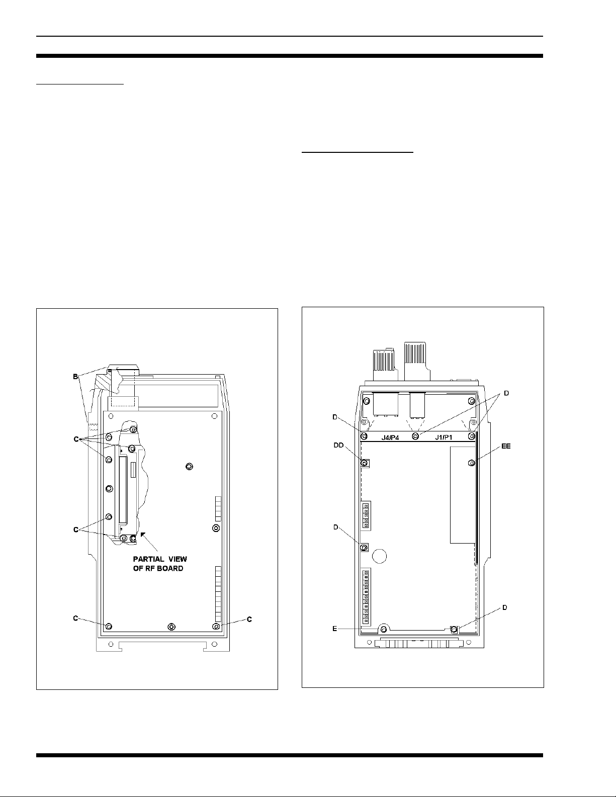
RF Board Access
Holes are located in t he RF Board shield for alignment
of the Reference Oscillator (U3), Modulation Balance pot
(R18), VCO Modulation pot (R19), 2nd Local Oscillator
Adjustment (T1), and the Quadrature D etector Adjustment
(T2). To align these items, shield removal is not necessary.
If removal of the RF Board from the case is necessary,
first remove the UDC antenna jack and the top RF antenna
jack w ith approp riate spanner w renches. Next, remove the
five (5) Torx screws (B) that secure the shield then lift and
remove the shield. Remove the two (2) remaining Torx
screws (C) near the Power Amplif ier Module. The RF Board
and eggcrate casting can now be lifted from the Rear Cover
to gain access to the chip component side of th e board. If
necessary, the RF Board can be separated from the eggcrate
casting. Remove the two (2) Torx screws that secure the
Power Amplifier Module and remove the four (4) scre ws on
the chip component side of the board that secure it to the
casting.
Reassemble the unit in reverse order. Observe screw
lengths.
Control Board Access
To gain partial access to the Control Board, remove the
five (5) screws (D) securing the shield and board. An earlier
Front Cover Assem bly has an additional screw located just
below connectors J4/P4 (DD). See Figure 8. Remove the
shield.
Many of the test points on the Control Board are accessible at this point; however, the Front Cover Assembly
should not be powered-up without first reinstalling the
screw into the lower right-hand hole to ground the board.
Also, the three (3) screws securing the top flex connectors
need to be reinstalled for good flex connections. USE CAU-
14
Figure 7 - RF Boa r d A ccess
Figure 8 - Contr ol Board Access
Page 15

LBI-38378D
TION: Installation of screws that are longer than the originals may damage the LCD Board, flex circuits or the
threads.
To remove the Control Board, remove the Torx screw
(E) in the lower left-hand corner that supplies battery power
to the board. An earlier Front Cover Assembly has an additional screw located just below connectors J1/P1 (EE). Lift
the board and carefully unplug Speaker Flex plug P3 from
J3 on the Control Board. Avoid bending this or any other
flex circuits at shar p an gles. Th e Co ntr ol Boar d ma y now be
removed. Note the battery power and ground connections at
the bottom of the board where the screws have been removed.
Speaker, Microphone and Flex Circuit Access
Remove the Control Board as previously stated and
then remove the six (6) Torx screws that secure the die-cast
shield. Remove the die-cast shield by lifting the top end first
and sliding it towards the top of the radio. The internal
speaker, microphone, Keypad and UDC Flex circuits are
now partially accessible. See Fig ure 9.
UDC Flex/UDC/Monitor Button/PTT Switch
Assembly Removal
If UDC Flex/UDC/Monitor Button/PTT Switch assembly removal is necessary, first un-solder the microphone.
With a spanner wrench, remove the UDC securing screw
(the UDC ground pin). Remove the insulator (foam or plastic) on the inside side-rail of the case. Lift the UDC/Monitor
Button/PTT Switch assembly from the side of the case and
slide the flex through the slot
Earlier Front Cover Assembly Keypad Flex
Removal
To remove the Keypad Flex, first remove the UDC
Flex/UDC/Monitor Button/PTT Switch assembly as previously stated. Next remove the knobs using the hex driver.
Unscrew the two (2) screws securing the top panel and lift
and remove the panel. Lift the Emergency Button Board by
carefully unplugging J6 from P6. With a spanner wrench,
remove the nuts securing the volume and channel controls
and carefully slide the controls inside the radio. Unscrew the
two (2) screws (G and GG) and remove th e J10/P10 Zebra
strip securing plate (HH). See Figure 10. The Keypad Flex
is now free for removal.
Figure 9 - Speaker, Microphone And Flex Circuit Access
Figure 10 - Keypad Flex And LCD Board Access
15
Page 16
LBI-38378D
BLOCK DIA G RAM
16
Figure 11 - Rear Cover Assembly Block Diagram
Page 17

BLOCK DIA G RAM
LBI-38378D
Figure 12 - Front Cover Assembly (Earlier) And Control Board Block Diagram
17
Page 18

LBI-38378D
Later Front Cover Assembly Keypad Flex Removal
To remove the Keypad Flex, first remove the UDC
Flex/UDC/Monitor Button/PTT Switch assembly as previously stated. Next remove the screw securing the emergency switch support (G) then remove the support. Remove
the knobs using the hex driver. With a spanner wrench, remove the nuts securing the volume and channel controls and
carefully slide the controls inside the radio. Unscrew the
two (2) screws that secure the J10/P10 connection at the
bottom of the LCD Board. Remove the screws, the plate and
the rubber pad. The Keypad Flex is now free for removal.
Speaker Flex Removal
In order to replace the Speaker Flex, it must be un-soldered from the speaker and the Battery Plate.
LCD Board Access
To remove th e LCD Bo ard, partial removal (actually repositioning of the top areas) of the Keypad Flex is required.
UDC Flex/UDC /Monitor Button/PTT Switch assembly removal is not necessary.
After the top areas of the Keypad Flex have been freed
as previously outlined, the LCD Board can be removed. At
this point is the disassembly process an earlier Front Cover
Assembly has two (2) screws on the left side as view from
the back (J and JJ) and a later assembly has a single screw
in the upper left-hand side (J). See Figure 10.
Ericsson Inc.
Private Radio Systems
Mountain View Road
Lynchburg, V irginia 24502
1-800-528-771 1 ( Outside USA, 804-528-7711 ) Printed in U.S.A.
 Loading...