

Page 1

ADSL Wireless RouterADSL Wireless Router
ADSL Wireless RouterADSL Wireless Router
ADSL Wireless Router
HN290dpHN290dp
HN290dpHN290dp
HN290dp
Quick Installation GuideQuick Installation Guide
Quick Installation GuideQuick Installation Guide
Quick Installation Guide
Page 2

TT
TT
T
able of Contentsable of Contents
able of Contentsable of Contents
able of Contents
INTRODUCTION ............................. 3
Delivery Check....................................... 3
Requirements........................................ 4
Placement ............................................. 5
INSTALLA TION................................ 6
CONFIGURATION........................... 9
PRODUCT DESCRIPTION .............11
Back Panel and Connectors ................ 11
Front Panel and LED Indicators............ 11
ADDITIONAL INFORMA TION..........13
How to Read the User Guide ............... 13
How to Uninstall USB Drivers .............. 13
IMPORT ANT INFORMA TION ..........14
Product Care and Maintenance............ 14
Regulatory Information ........................ 1 5
ess in methodologyess in methodology
ess in methodologyess in methodology
ess in methodology
, design, design
, design, design
, design
he copyright ownerhe copyright owner
he copyright ownerhe copyright owner
he copyright owner
..
..
.
Page 3

INTRODUCTIONINTRODUCTION
INTRODUCTIONINTRODUCTION
INTRODUCTION
This Quick Installation Guide provides instructions about how to install and getting started with the Ericsson ADSL Wireless Router
HN290dp in a Windows environment.
For detailed information about the product and configuration possibilities, please refer to the User Guide which is included on the supplied “Drivers & Documentation” CD.
The User Guide also includes a glossary where you can find explanations to unfamiliar or technical terms.
DELIVER DELIVER
DELIVER DELIVER
DELIVER
Y CHECKY CHECK
Y CHECKY CHECK
Y CHECK
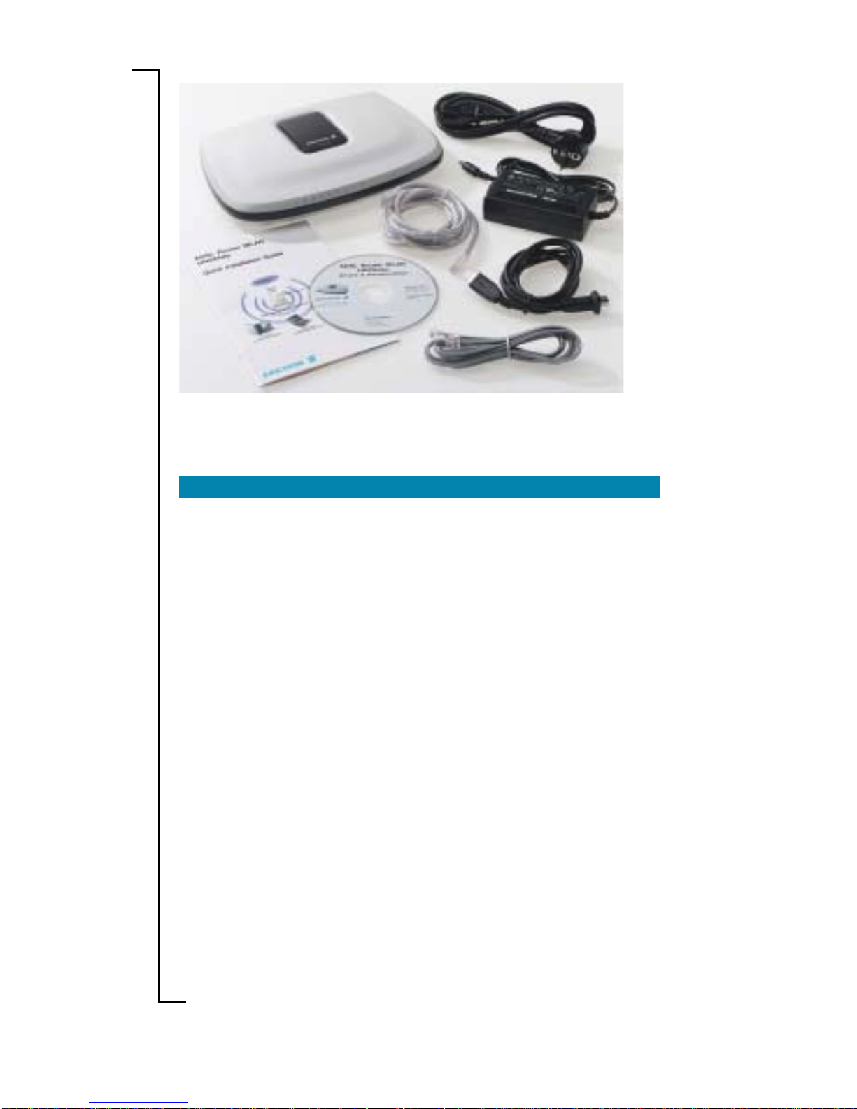
Check the contents of your HN290dp package which should include
the items listed below (see also illustration on the next page):
• The ADSL Wireless Router HN290dp
• A Power Supply Adapter with connecting cable
• Drivers & Documentation CD (including drivers for USB
installation, a printable User Guide and Acrobat Reader)
• ADSL Line Cable
• Ethernet cable
• USB cable
• Quick Installation Guide.
If something is missing or damaged, please contact your ADSL router
provider.
NOTE!NOTE!
NOTE!NOTE!
NOTE! Your HN290dp package may also include other materials
provided by your ADSL operator.
Introduction 3
Page 4
4 Introduction
REQUIREMENTS REQUIREMENTS
REQUIREMENTS REQUIREMENTS
REQUIREMENTS
T o use the ADSL Wireless Router HN290dp, you will requir e an ADSL
service subscription from your broadband service provider.
Computer(s) that should be connected to the HN290dp must meet
the following requirements:
•
For wireless computer(s)For wireless computer(s)
For wireless computer(s)For wireless computer(s)
For wireless computer(s);
- A wireless adapter installed. This could for example be a
PCMCIA wireless card for your laptop, a wireless PCI card or
a USB wireless adapter for your desktop PCs.
- Operating system: Windows 98/98SE, Me, 2000 or XP.
•
For computer(s) connected via the EthernetFor computer(s) connected via the Ethernet
For computer(s) connected via the EthernetFor computer(s) connected via the Ethernet
For computer(s) connected via the Ethernet
interfaceinterface
interfaceinterface
interface;
- 10/100Base-T Network Interface Card (NIC) installed
- Operating system: Windows 95 or higher , Mac OS 7.5 or
higher .
•
For a computer connected via the USB interfaceFor a computer connected via the USB interface
For a computer connected via the USB interfaceFor a computer connected via the USB interface
For a computer connected via the USB interface;
- USB port
- CD-ROM drive (for installation of drivers)
- Operating system: Windows 98/98SE, Me, 2000 or XP.
Prior to connecting and installing any of the equipment, read the
information about “Product Care and Maintenance” on page 14.
ADSL Wireless RouterADSL Wireless Router
ADSL Wireless RouterADSL Wireless Router
ADSL Wireless Router
HN290dpHN290dp
HN290dpHN290dp
HN290dp
Connecting cable toConnecting cable to
Connecting cable toConnecting cable to
Connecting cable to
Power Supply AdapterPower Supply Adapter
Power Supply AdapterPower Supply Adapter
Power Supply Adapter
Power SupplyPower Supply
Power SupplyPower Supply
Power Supply
AdapterAdapter
AdapterAdapter
Adapter
EthernetEthernet
EthernetEthernet
Ethernet
CableCable
CableCable
Cable
ADSL Line CableADSL Line Cable
ADSL Line CableADSL Line Cable
ADSL Line Cable
CD-ROMCD-ROM
CD-ROMCD-ROM
CD-ROM
Quick InstallationQuick Installation
Quick InstallationQuick Installation
Quick Installation
GuideGuide
GuideGuide
Guide
USBUSB
USBUSB
USB
CableCable
CableCable
Cable
Figure: Contents of the standard HN290dp package
Page 5
Introduction 5
PLACEMENT PLACEMENT
PLACEMENT PLACEMENT
PLACEMENT
The HN290dp can be mounted on the wall or simply placed on a flat
surface.
NOTE!NOTE!
NOTE!NOTE!
NOTE! Proper ventilation is necessary to prevent the product from
over-heating. Do not block or cover the slots and openings on the
device, which are intended for ventilation and proper operation.
In a wireless configuration the HN290dp is designed to reach 50-100
meters indoors and up to 300 meters outdoors. When choosing a
location for your router, keep in mind that this length is affected by a
number of rules, such as:
• The more walls the signal has to pass, the shorter will the signal
reach.
• The thicker the wall is, the shorter will the signal reach.
• Keep the HN290dp away from equipment that might disturb
the signal (such as bluetooth devices, microwave ovens and 2.4
GHz cordless phones).
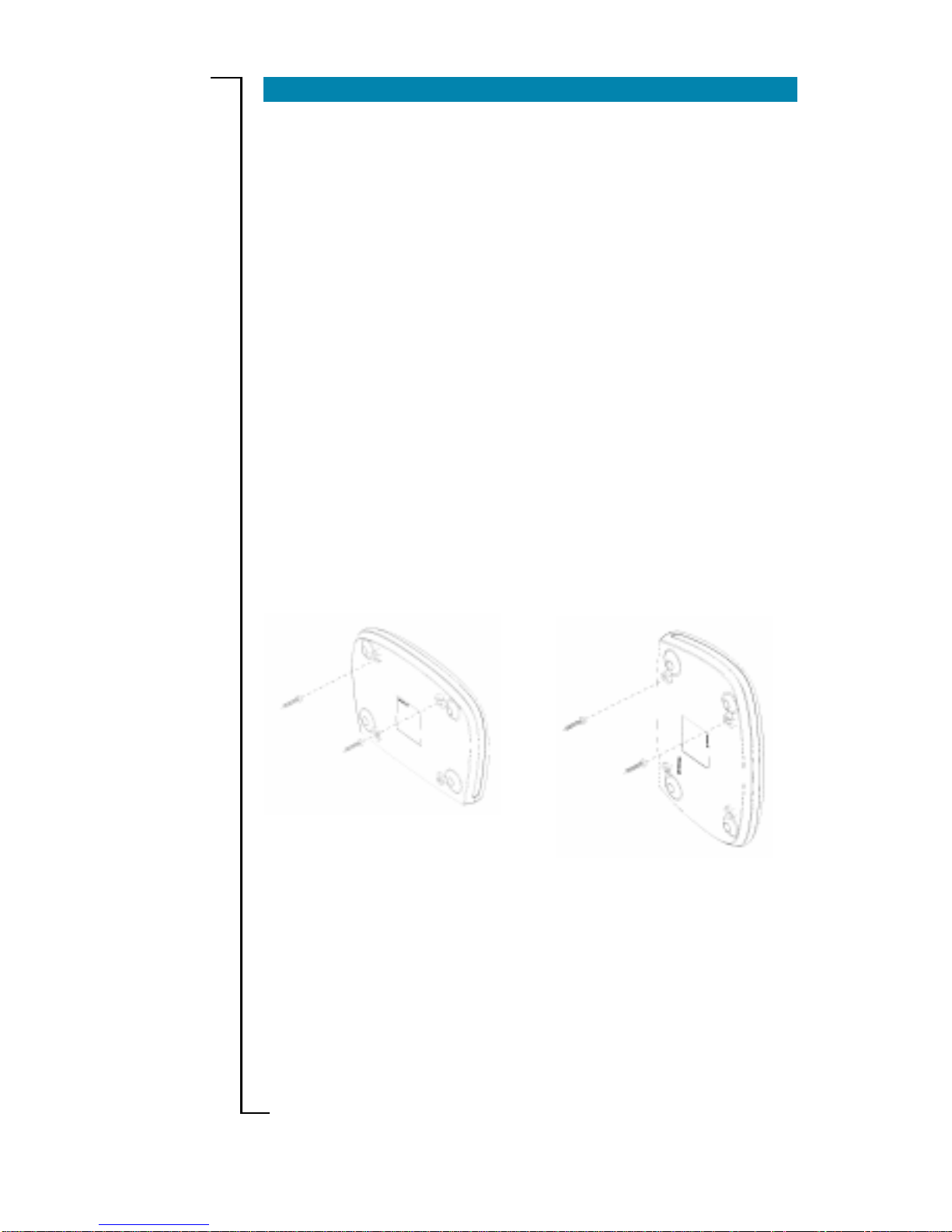
If you choose to wall mount the router , use two scr ews and two of the
mounting slots on the bottom of the unit as shown in the illustration
below:
Figure: Wall mounting of the HN290dp
126 mm
112,5 mm
Note that the transparent top cover can be rotated to ensure that the
logo is correctly positioned for various mounting positions.
Page 6

6 Installation
INSTINST
INSTINST
INST
ALLAALLA
ALLAALLA
ALLA
TIONTION
TIONTION
TION
This chapter includes a step-by-step description how to install the
HN290dp to computer(s) in different network environments (wireless and/or via cables).
1 1
1 1
1
CONNECT THE ADSL LINECONNECT THE ADSL LINE
CONNECT THE ADSL LINECONNECT THE ADSL LINE
CONNECT THE ADSL LINE
Use the provided
ADSL Line cable ADSL Line cable
ADSL Line cable ADSL Line cable
ADSL Line cable to connect the
ADSL ADSL
ADSL ADSL
ADSL port
on the HN290dp to your ADSL outlet (splitter/filter or phone outlet).
2A 2A
2A 2A
2A
CONNECT WIRELESS COMPUTER(S)CONNECT WIRELESS COMPUTER(S)
CONNECT WIRELESS COMPUTER(S)CONNECT WIRELESS COMPUTER(S)
CONNECT WIRELESS COMPUTER(S)
1.1.
1.1.
1.
Install wireless adapter(s)Install wireless adapter(s)
Install wireless adapter(s)Install wireless adapter(s)
Install wireless adapter(s) to the computer(s) that you
want to connect to the HN290dp. Follow the instructions provided together with the equipment.
NOTE!NOTE!
NOTE!NOTE!
NOTE! Before installing a wireless adapter, find and write down
the MAC address of the product as you might need it later when
configuring your HN290dp. You will normally find the MAC address on the product label of your WLAN adapter. MAC addresses are given in the form 00:90:96:1A:2B:3C and only numbers 0 through 9 and letters a through f are allowed.
2.2.
2.2.
2. If your client PC is correctly configured it will automatically detect
and connect to the HN290dp.
Now, continue to step 2B if you also want to connect computer(s)
via cables. Otherwise proceed to step 3.
2B 2B
2B 2B
2B
CONNECT COMPUTER(S) VIA CABLESCONNECT COMPUTER(S) VIA CABLES
CONNECT COMPUTER(S) VIA CABLESCONNECT COMPUTER(S) VIA CABLES
CONNECT COMPUTER(S) VIA CABLES
1.1.
1.1.
1.
Connect a client PC:Connect a client PC:
Connect a client PC:Connect a client PC:
Connect a client PC:
NOTE!NOTE!
NOTE!NOTE!
NOTE! If you want to use both the ETHERNET and USB ports,
connect them to two different PCs. It is NOT recommended to
connect one PC to both the ETHERNET and USB ports simultaneously.
- to the ETHERNET port- to the ETHERNET port
- to the ETHERNET port- to the ETHERNET port
- to the ETHERNET port
Attach one end of the provided
Ethernet cable Ethernet cable
Ethernet cable Ethernet cable
Ethernet cable to the
ETHERNETETHERNET
ETHERNETETHERNET
ETHERNET port on your HN290dp.
Connect the other end to the Ethernet adapter on your client PC.
This port is most likely marked with this symbol:
-- OR ---- OR --
-- OR ---- OR --
-- OR --
Page 7

Installation 7
- to the USB port- to the USB port
- to the USB port- to the USB port
- to the USB port
NOTE!NOTE!
NOTE!NOTE!
NOTE! DO NOT connect the USB cable yet.
Insert the provided “Drivers & Documentation” CD and follow the
instructions given in step 4.
3 3
3 3
3
CONNECT THE POWER SUPPLCONNECT THE POWER SUPPL
CONNECT THE POWER SUPPLCONNECT THE POWER SUPPL
CONNECT THE POWER SUPPL
YY
YY
Y
Connect the provided
Power cable Power cable
Power cable Power cable
Power cable to the
POWERPOWER
POWERPOWER
POWER socket on
your HN290dp and plug the power supply adapter into a power
source.
Start the HN290dpStart the HN290dp
Start the HN290dpStart the HN290dp
Start the HN290dp by pressing the
Power Power
Power Power
Power button on the back
of the HN290dp.
4 4
4 4
4
INSTINST
INSTINST
INST
ALL USB DRIVERSALL USB DRIVERS
ALL USB DRIVERSALL USB DRIVERS
ALL USB DRIVERS
NOTE!NOTE!
NOTE!NOTE!
NOTE! This should only be done if you have connected a computer
via the USB interface, otherwise continue to step 5.
DO NOT connect the USB cable until you are instructed by the installation program.
For USB connection you need to install USB drivers to your PC.
Follow the instructions below to install USB drivers and connect the
HN290dp to the USB interface.
1.1.
1.1.
1. Close ALL Windows applications and insert the provided “Drivers
& Documentation” CD into your CD-ROM drive.
2.2.
2.2.
2. The CD starts automatically and the following window appears:
If Autostart fails, select
Start > RunStart > Run
Start > RunStart > Run
Start > Run, type
D:\startup.exeD:\startup.exe
D:\startup.exeD:\startup.exe
D:\startup.exe
(where D: is the letter of your CD-ROM drive) and press Enter.
Page 8

8 Installation
5 5
5 5
5
VERIFY THE INSTVERIFY THE INST
VERIFY THE INSTVERIFY THE INST
VERIFY THE INST
ALLAALLA
ALLAALLA
ALLA
TIONTION
TIONTION
TION
Check the control lamps (LEDs) on the front of the HN290dp (according to the description on page 12) to verify that the installation has
been properly done.
Then proceed to chapter “CONFIGURATION” on the next page to
get instructions about how to configure the HN290dp and to finish
the installation.
4.4.
4.4.
4. Click
Next>Next>
Next>Next>
Next>. Files will now be copied to your harddisk and when
completed the following window appears:
5.5.
5.5.
5. Now, connect the provided
USB cableUSB cable
USB cableUSB cable
USB cable to the
USB USB
USB USB
USB port on
your HN290dp. Connect the other end to the USB port on your
client PC. This port is most likely marked with this symbol:
6.6.
6.6.
6. Windows will now detect the new USB device and finalize the
installation.
NOTE!NOTE!
NOTE!NOTE!
NOTE! If the Digital Signature Not Found window (or similar)
appears, just click Y es (or Continue Anyway) to proceed.
7.7.
7.7.
7. Click
Finish Finish
Finish Finish
Finish to close the InstallShield Wizard. Click
>>> Exit>>> Exit
>>> Exit>>> Exit
>>> Exit
<<<<<<
<<<<<<
<<< in the Welcome page of the CD to close this window .
3.3.
3.3.
3. Select
Install USB DriverInstall USB Driver
Install USB DriverInstall USB Driver
Install USB Driver and wait until the following window
is displayed:
Page 9

Configuration 9
CONFIGURACONFIGURA
CONFIGURACONFIGURA
CONFIGURA
TIONTION
TIONTION
TION
This chapter describes how to access the built-in configuration tool
and start the Configuration wizard that will guide you through the
necessary steps to make the initial configuration of the HN290dp.
1.1.
1.1.
1. Start a web browser and type
http://192.168.0.1http://192.168.0.1
http://192.168.0.1http://192.168.0.1
http://192.168.0.1 (the pri-
vate IP address for the HN290dp) in the URL field and hit Enter.
2.2.
2.2.
2. The login window is displayed:
3.3.
3.3.
3. Type
admin admin
admin admin
admin in the fields for both “User name” och “Password”
and click
OKOK
OKOK
OK.
It is recommended that you later change the default User name
and Password to avoid unauthorized access to the configuration
pages. See the User Guide.
4.4.
4.4.
4. The welcome page of the Configuration tool is now displayed as
shown on the next page:
NOTE!NOTE!
NOTE!NOTE!
NOTE! If this login window does not appear it might depend on
that your PC can’t access the HN290dp due to incorrect network
configuration. Check the TCP/IP settings in your PC and verify
that the option “Obtain an IP address automatically” (DHCP) is
configured and that your web browser does not have any Proxy
settings.
Page 10

10 Configuration
5.5.
5.5.
5. Click on the
Configuration WizardConfiguration Wizard
Configuration WizardConfiguration Wizard
Configuration Wizard button and follow the
instructions given on-scrren.
NOTE!NOTE!
NOTE!NOTE!
NOTE! Step 3 of the wizard consist of security settings for the
Firewall and the wireless LAN, but they are not mandatory in order
to complete the wizard. Whenever you want you can access the
wizard or Andvanced Configuration to change and/or make new
settings. All configuration options are described in the User Guide.
6.6.
6.6.
6. When you have completed the wizard and reached the last page
(step 4) it is important that you click the
Save ConfigurationSave Configuration
Save ConfigurationSave Configuration
Save Configuration
button to save all configuration settings to non-volatile memory.
The installation and configuration of the HN290dp is now completed
but your Internet Service Provider may have provided you additional
instructions (in this package or separately) about account setup, additional software installation, and/or Internet usage. In that case, please
follow those instructions to complete your Internet connection setup.
For further information about the product, advanced configuration
instructions and troubleshooting, please refer to the User Guide which
is included on the supplied “Drivers & Documentation” CD.
Page 11

Product Description 11
PRODUCT DESCRIPTIONPRODUCT DESCRIPTION
PRODUCT DESCRIPTIONPRODUCT DESCRIPTION
PRODUCT DESCRIPTION
BACK P BACK P
BACK P BACK P
BACK P
ANEL AND CONNECTORSANEL AND CONNECTORS
ANEL AND CONNECTORSANEL AND CONNECTORS
ANEL AND CONNECTORS
The illustration below describes connectors and buttons on the
HN290dp and can be used as a reference when connecting the r outer .
ADSLADSL
ADSLADSL
ADSL
For connecting
the HN290dp to
the ADSL service
port, using the
supplied ADSL
Line cable.
POWERPOWER
POWERPOWER
POWER socket for
connecting the
HN290dp to a power
source, using the
supplied Power
Adapter with connecting cable.
ETHERNETETHERNET
ETHERNETETHERNET
ETHERNET
Ethernet 10/100 Base-T port
for connecting the HN290dp
to a client PC, using the
supplied Ethernet cable.
USBUSB
USBUSB
USB
For connecting
the HN290dp to
a PC USB port,
using the
supplied USB
cable.
POWERPOWER
POWERPOWER
POWER button
for turning On/Off
the HN290dp
RESETRESET
RESETRESET
RESET button (tiny hole)
used to restore the
HN290dp to its original
factory default settings.
Figure: Back Panel on the HN290dp
Figure: Front Panel on the HN290dp
FRONT P FRONT P
FRONT P FRONT P
FRONT P
ANEL AND LED INDICAANEL AND LED INDICA
ANEL AND LED INDICAANEL AND LED INDICA
ANEL AND LED INDICA
TORSTORS
TORSTORS
TORS
The HN290dp is equipped with six LEDs on the front panel as shown
in the illustration below. A general description of each LED is pr ovided
in the table on the next page (from left to right).
Page 12

12 Product Description
LEDLED
LEDLED
LED
StatusStatus
StatusStatus
Status
DescriptionDescription
DescriptionDescription
Description
Unlit Power off.
Solid Power on.
Unlit Power off or initial self-test of the unit is
OK.
Blinking Software is downloading or updating of
operation parameters is in progress.
Solid Failure during initial self-test or program-
ming FLASH memory.
Unlit Power off or no Ethernet link detected.
Blinking User data is going through the Ethernet
port.
Solid Ethernet connection is OK.
Unlit Power off or waiting for USB connection
going up.
Blinking User data is going through the USB port.
Solid USB connection is OK.
Unlit Power off or no radio signal (WLAN card is
not present or fails to function).
Blinking T raffic is going through the WLAN interface.
Solid The Wireless LAN interface is ready.
Unlit Power off.
Blinking ADSL line connection is handshaking or
training is in progress.
Solid ADSL line connection is OK.
Table: Description of LEDs on the HN290dp
PWR
DIAG
LAN
USB
WLAN
DSL
Page 13

Additional Information 13
ADDITIONAL INFORMAADDITIONAL INFORMA
ADDITIONAL INFORMAADDITIONAL INFORMA
ADDITIONAL INFORMA
TIONTION
TIONTION
TION
HOW TO READ THE USER GUIDE HOW TO READ THE USER GUIDE
HOW TO READ THE USER GUIDE HOW TO READ THE USER GUIDE
HOW TO READ THE USER GUIDE
Read the provided User Guide if you want to have further information
about the HN290dp or instructions about how to perform advanced
configuration and troubleshooting.
1.1.
1.1.
1. Insert the provided “Drivers & Documentation” CD into your CD-
ROM and wait for the Welcome window to appear.
2.2.
2.2.
2. Select
User GuideUser Guide
User GuideUser Guide
User Guide and the User Guide will be presented in a
separate window.
NOTE!NOTE!
NOTE!NOTE!
NOTE! T o be able to open the User Guide you have to have Acrobat
Reader installed on your PC. If you don’t have that, you can select
Install Acrobat ReaderInstall Acrobat Reader
Install Acrobat ReaderInstall Acrobat Reader
Install Acrobat Reader to have it installed. Then select User
Guide again.
HOW TO UNINST HOW TO UNINST
HOW TO UNINST HOW TO UNINST
HOW TO UNINST
ALL USB DRIVERSALL USB DRIVERS
ALL USB DRIVERSALL USB DRIVERS
ALL USB DRIVERS
If you want to uninstall the USB drivers, proceed as follows:
1.1.
1.1.
1. Insert the provided “Drivers & Documentation” CD into your CD-
ROM and wait for the Welcome window to appear.
2.2.
2.2.
2. Select
Uninstall USB DriverUninstall USB Driver
Uninstall USB DriverUninstall USB Driver
Uninstall USB Driver and follow the on-screen in-
structions.
The uninstallation can also be done from Windows Control Panel and
the choice “Add/Remove Programs”. In the list of “Currently installed
programs” you should select “Ericsson HN290d USB Driver V er 3.0”
and then click
RemoveRemove
RemoveRemove
Remove.
Page 14

14 Important Information
IMPORIMPOR
IMPORIMPOR
IMPOR
TT
TT
T
ANT INFORMAANT INFORMA
ANT INFORMAANT INFORMA
ANT INFORMA
TIONTION
TIONTION
TION
PRODUCT CARE AND MAINTENANCE PRODUCT CARE AND MAINTENANCE
PRODUCT CARE AND MAINTENANCE PRODUCT CARE AND MAINTENANCE
PRODUCT CARE AND MAINTENANCE
NOTE!NOTE!
NOTE!NOTE!
NOTE! This is guidelines for safe and efficient use. Read this infor-
mation before using your Ericsson ADSL Wireless Router HN290dp.
Y our ADSL Wireless Router HN290dp is a highly sophisticated electronic device. To get the most out of your r outer, be sur e to r ead the
following text about product care, safety and efficient use.
Do notDo not
Do notDo not
Do not expose the product to liquid or moisture.
Do notDo not
Do notDo not
Do not expose the product to extreme temperatures, neither hot nor
cold.
Do notDo not
Do notDo not
Do not expose the product to lit candles, cigarettes, cigars, open
flames, etc.
Do notDo not
Do notDo not
Do not drop, throw or try to bend the product since r ough treatment
could damage your product.
Do notDo not
Do notDo not
Do not attempt to disassemble the product, the warranty is no longer
valid if the warranty seal has been broken. The product does not
contain consumer serviceable components. Service should only be
performed by Certified Service Centres.
Do notDo not
Do notDo not
Do not allow children to play with the router as it contains small
parts that could be detached and create a choking hazard.
AA
AA
A
voidvoid
voidvoid
void using this telephone equipment during an electrical storm.
There may be a remote risk of electric shock fr om lightning.
Use onlyUse only
Use onlyUse only
Use only original Ericsson components and replacement parts. Fail-
ure to do so may result in performance loss, damage to the product,
fire, electric shock or injury, and will invalidate the warranty.
Use onlyUse only
Use onlyUse only
Use only the power supply adapter that comes with the unit. Re-
placement power supply adapters can be obtained from Ericsson
upon request.
Treat the product with care, keep it in an clean and dust free place.
Use only a soft, damp cloth to clean the product.
Page 15

Important Information 15
REGULA REGULA
REGULA REGULA
REGULA
TORTOR
TORTOR
TOR
Y INFORMAY INFORMA
Y INFORMAY INFORMA
Y INFORMA
TIONTION
TIONTION
TION
ApprovalsApprovals
ApprovalsApprovals
Approvals
CE, FCC part 15, FCC part 68, UL 1950.
EU DirectiveEU Directive
EU DirectiveEU Directive
EU Directive
The HN290dp meet the following EU directives for the CE mark:
• 73/23/EEC, Low Voltage Dir ective (LVD)
• 89/336/EEC, Electromagnetic Compatibility Directive (EMC)
• 1999/5/EC, Radio Equipment and Telecommunication T erminal
Directive (R&TTE).
CE RequirCE Requir
CE RequirCE Requir
CE Requir
ementement
ementement
ement
Hereby, Ericsson AB, declares that this ADSL Router WLAN
HN290dp, is in conformity with the essential requirements and other
relevant provisions of the R&TTE directive 1999/5/EC.
Declaration of Conformity in the User Guide.
Access Point Frequency Band:Access Point Frequency Band:
Access Point Frequency Band:Access Point Frequency Band:
Access Point Frequency Band:
2412 MHz to 2472 MHz (subject to local regulations).
Power SupplyPower Supply
Power SupplyPower Supply
Power Supply
The ADSL Wireless Router HN290dp is equipped with an external
power supply adapter rated at a 100-240 V AC/50-60 Hz input transformed to 12 VDC/1 A.
NOTE! NOTE!
NOTE! NOTE!
NOTE! For use only with approved supplied power adapter.
EnvirEnvir
EnvirEnvir
Envir
onmental Informationonmental Information
onmental Informationonmental Information
onmental Information
Maximum Environmental V alues during use:
• Temperature: 0oC to +40oC
• Humidity: 5% to 85% RH, non-condensing.
Intended UseIntended Use
Intended UseIntended Use
Intended Use
The HN290dp is intended for indoor public and private use.
CAUTIONCAUTION
CAUTIONCAUTION
CAUTION
Changes or modifications to this product not authorized by the manufacturer could void your authority to operate the equipment and invalidate approvals.
Page 16

© Ericsson AB 2003
EN/LZT 108 6201 R2
 Loading...