

Page 1
ADSL Modem
HM210dp/di
User Guide
Page 2

ADSL Modem
HM210dp/di
User Guide
.
ii
EN/LZT 108 6492 R2 – October 2003
Copyright
Ericsson AB – 2003 All Rights Reserved
Disclaimer
The contents of this document are subject to revision without notice due to
continued progress in methodology, design, and manufacturing. Ericsson shall
have no liability for any error or damages of any kind resulting from the use of
this document.
Abstract
This User guide describes how to install and set up the Ericsson ADSL
Modem HM210dp/di in a Windows environment, and how to customize its
configuration to get the most out of the product.
Trademark List
Windows
Windows is a registered trademark of Microsoft
Corporation
Enclosure List
Page 3

Contents
EN/LZT 108 6492 R2 – October 2003
iii
Contents
1 Introduction 1
1.1 About this User Guide 1
1.2 About the ADSL Modem HM210d 1
1.2.1 Features 1
2 Hardware Description and Installation 2
2.1 Before You Start 2
2.1.1 Package Contents 2
2.1.2 Subscription for ADSL Service 2
2.1.3 System Requirements 2
2.2 Physical Appearance 3
2.2.1 Front Panel and LED Indicators 3
2.2.2 Back Panel and Connectors 4
2.3 Choosing a Place for the Router 4
2.4 Connecting the Hardware 5
3 Local PC Configuration 6
3.1 Configuring PCs as DHCP Clients 6
3.1.1 In Windows 95, 98/98SE and Me: 6
3.1.2 In Windows 2000: 7
3.1.3 In Windows XP: 7
3.2 Assigning Static IP Addresses to your PCs 8
3.2.1 In Windows 95, 98/98SE and Me: 8
3.2.2 In Windows 2000: 9
3.2.3 In Windows XP: 9
4 Getting Started with the Configuration Manager 10
4.1 Accessing the Configuration Manager 10
4.2 Functional Layout 11
4.2.1 Commonly Used Buttons and Icons 12
Page 4

Contents
iv EN/LZT 108 6492 R2 - October 2003
4.3 The Home Page and System View Table 13
4.4 Commiting Changes and Rebooting 15
4.4.1 Rebooting the HM210dp/di using Options 16
4.5 Quick Configuration 18
5 Basic Configuration 21
5.1 Configuring the ATM Virtual Circuit 21
5.1.1 Adding ATM VCs 21
5.1.2 Modifying ATM VCs 23
5.2 Configuring PPP Interfaces 24
5.2.1 Adding PPP Interfaces 24
5.2.2 Checking Your Connection Status 27
5.2.3 Modifying and Deleteing PPP Interfaces 28
5.3 Configuring EoA Interfaces 29
5.3.1 Adding EoA Interfaces 29
5.4 Configuring IPoA Interfaces 33
5.4.1 Adding IPoA Interfaces 33
5.4.2 Checking Your Connection Status 35
5.5 Bridging Connection Mode 36
5.5.1 Defining Bridge Interfaces 36
5.5.2 Check Your Connection Status 37
5.5.3 Deleting a Bridge Interface 37
6 Configuring IP Routes 38
6.1 Overview of IP Routes 38
6.2 Viewing the IP Routing Table 39
6.3 Adding IP Routes 41
7 Configuring DHCP 42
7.1 Overview of DHCP 42
7.2 DHCP Modes 42
7.3 Configuring DHCP Server 43
7.3.1 Creating DHCP Server Address Pools 44
Page 5

Contents
EN/LZT 108 6492 R2 - October 2003
v
7.3.2 Enabling DHCP Server Mode 46
7.3.3 Configuring Your PCs as DHCP Clients 47
7.3.4 Viewing, Modifying and Deleting Address Pools 47
7.3.5 Excluding IP Addresses from a Pool 48
7.3.6 Viewing Current DHCP Address Assignments 48
7.4 Configuring DHCP Relay 49
7.4.1 Defining the DHCP Relay Interface(s) 49
7.4.2 Enabling DHCP Relay Mode 50
7.4.3 Configuring Your PCs as DHCP Clients 51
8 Configuring NAT 52
8.1 Overview of NAT 52
8.2 Viewing NAT Configuration 53
8.3 Viewing NAT Rules and Rule Statistics 55
8.4 Viewing Current NAT Translations 57
8.5 Adding NAT Rules 59
8.5.1 The NAPT Rule 59
8.5.2 The RDR Rule 60
8.5.3 The BASIC Rule 62
8.5.4 The FILTER Rule 64
8.5.5 The BIMAP Rule 66
8.5.6 The PASS Rule 68
9 Configuring DNS Server Addresses 70
9.1 Assigning DNS Addresses 70
9.2 Overview of DNS Relay 71
9.3 Configuring DNS Relay 71
10 Configuring RIP 74
10.1 Overview of RIP 74
10.2 Configuring the RIP 75
10.3 Viewing RIP Statistics 76
Page 6

Contents
vi EN/LZT 108 6492 R2 - October 2003
11 Configuring Firewall Settings 78
11.1 Global Firewall Settings 78
11.2 Configuring IP Filters 80
11.2.1 Viewing Your IP Filter Configuration 81
11.2.2 Configuring IP Filter Global Settings 82
11.2.3 Creating IP Filter Rules 82
11.2.4 Viewing IP Filter Statistics 88
11.2.5 Managing Current IP Filter Sessions 89
11.3 Blocking Specific Protocols 90
12 Administration Tasks 93
12.1 Changing the System Date and Time 93
12.2 Configuring User Names and Passwords 94
12.3 Upgrading the Software 96
12.4 Using Diagnostics 97
12.5 Modifying Port Settings 99
12.5.1 Accessing a Server with a Non-Standard Port Number 99
12.6 Viewing System Alarms 100
13 Viewing DSL Line Information 101
14 Troubleshooting 104
14.1 LEDs 104
14.2 Internet Access 105
14.3 Configuration Manager Program 106
14.4 Diagnosing Problem Using IP Utilities 106
14.4.1 How to use WINIPCFG 106
14.4.2 How to use IPCONFIG 107
14.4.3 How to use PING 108
15 Important Information 109
15.1 Product Care and Maintenance 109
15.2 License Agreement 110
Page 7

Contents
EN/LZT 108 6492 R2 - October 2003
vii
15.2.1 License 110
15.2.2 Term 110
15.2.3 Limited Warranty 110
15.2.4 Intended Use 111
15.2.5 Limitation of Liability 111
15.2.6 Governing Law 111
15.3 Regulatory Information 112
15.3.1 EU Directives 112
15.3.2 Safety Approvals 112
15.3.3 EMC Approvals 113
15.3.4 Telecom Approval 115
15.3.5 Caution 116
15.3.6 Power Supply 116
15.3.7 Environmental Information 116
15.3.8 Intended Use 117
16 Glossary 118
Page 8

Page 9

Introduction
EN/LZT 108 6492 R2 - October 2003
1
1 Introduction
Congratulations on becoming the owner of an Ericsson ADSL Modem
HM210dp/di. Your LAN (Local Area Network) will now be able to access the
Internet using your high-speed ADSL connection.
1.1 About this User Guide
This User Guide describes how to install and setup your HM210dp/di in a
Windows environment, and how to customize its configuration to get the
most out of your new product.
The Glossary includes abbreviations and explanations to technical terms
used in this guide.
1.2 About the ADSL Modem HM210d
The ADSL Modem HM210 comes in two versions: HM210dp and HM210di.
Both products offer the same features, but they rely on different types of
telephone line in order to provide the ADSL service. HM210dp offers ADSL
service over POTS (Plain Old Telephone System) lines, while HM210di
uses ISDN (Integrated Services Digital Network) lines to provide the ADSL
service.
1.2.1 Features
The main features of the HM210dp/di are listed below:
Internal ADSL modem for high-speed Internet access.
10/100Base-T Ethernet router to provide Internet connectivity to all
computers on your LAN.
Network Address Translation (NAT), Firewall and IP filtering
functions to provide security for your LAN.
Network configuration through DHCP Server and DHCP Relay.
Services including IP route and DNS configuration, RIP, and IP and
DSL performance monitoring.
Configuration Manager program you access via a web browser.
Page 10

Hardware Description and Installation
2 EN/LZT 108 6492 R2 - October 2003
2 Hardware Description and Installation
This chapter describes the product and provides instructions about how to
install the HM210dp/di in a PC/Windows environment.
2.1 Before You Start
2.1.1 Package Contents
Check the contents of the package against the shipping contents checklist
below. If any of the items is missing, please contact the ADSL modem
provider.
The ADSL Modem HM210dp/di
A Power Supply Adapter with connecting cable
ADSL Line Cable (RJ-11)
Ethernet Cable (RJ-45)
USB Cable
Quick Installation Guide
Documentation CD (including Acrobat Reader and this User Guide)
Your HM210dp/di package may also include other materials provided by
your ADSL operator.
2.1.2 Subscription for ADSL Service
To use the ADSL Modem HM210dp/di, you will require an ADSL service
subscription from your broadband service provider.
2.1.3 System Requirements
In order to use your HM210dp/di you must have the following:
One or more computers each containing an Ethernet 10/100Base-T
network interface card (NIC).
Page 11

Hardware Description and Installation
EN/LZT 108 6492 R2 - October 2003
3
An Ethernet hub/switch if you are connecting the device to more
than one computer.
For system configuration using the built-in Configuration Manager
program you need a web browser such as Internet Explorer v5.0 or
later, or Netscape v5.0 or later.
2.2 Physical Appearance
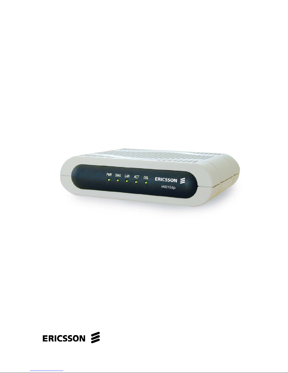
2.2.1 Front Panel and LED Indicators
The front panel of the HM210dp/di contains five control lamps (LEDs) that
indicate the status of the modem. A general description of each LED is
provided in the table below (from left to right):
Figure 1 - Front Panel of HM210dp
Label Status/Description
PWR On: Unit is powered on.
Off: Unit is powered off.
DIAG Flashes on/off at boot-up to indicate that the device
software is operational. Turns off after 10-15 seconds.
LAN On: Ethernet link established and active.
Off: No Ethernet link detected.
ACT Flashes when ADSL data activity occurs. May appear
solid when data traffic is heavy.
DSL On: ADSL link established and active.
Off: No ADSL link detected.
Table 1 - Description of LEDs
Page 12
Hardware Description and Installation
4 EN/LZT 108 6492 R2 - October 2003
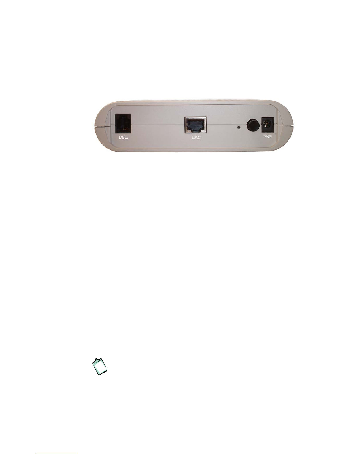
2.2.2 Back Panel and Connectors
The following figure illustrates the back panel of your HM210dp/di:
Figure 2 - Back Panel of the HM210dp/di
Description of connectors and buttons:
DSL – The DSL port is used for connecting the HM210dp/di to the
ADSL service port (splitter/filter or phone outlet) using the supplied
ADSL line cable (RJ11 – RJ11).
LAN – The LAN port (Ethernet 10/100 BaseT) connect the
HM210dp/di to your PC’s Ethernet port, or to the uplink port on your
LAN’s hub, using the supplied Ethernet cable (RJ45 – RJ45).
RESET button (tiny hole) – Used to reset and restore the
HM210dp/di to default settings.
Push a paper clicp into the hole and hold for three seconds before
releasing. Then wait for the device to finish boot up.
Power button – Used to switch the HM210dp/di ON and OFF.
PWR – Power socket for connecting the HM210dp/di to a power
outlet by using the supplied power adapter.
2.3 Choosing a Place for the Router
The HM210dp/di should be placed on a flat surface. Be sure to choose a
location that enables you to see the LEDs, is close to a power outlet, ADSL
outlet, and the PC.
NOTE! Proper ventilation is necessary to prevent the product from
over-heating. Do not block or cover the slots and openings on the
device, which are intended for ventilation and proper operation.
Page 13

Hardware Description and Installation
EN/LZT 108 6492 R2 - October 2003
5
2.4 Connecting the Hardware
Follow the procedures below to connect related devices.
NOTE! Before you begin, turn the power off for all devices. These
include your computer(s), your LAN hub/switch (if applicable), and
the HM210dp/di.
1. Connect to the ADSL Line
Connect one end of the provided ADSL Line cable to the port
labeled DSL on the back panel of the HM210dp/di. Connect the
other end to your ADSL service port (splitter/filter or phone outlet).
2. Connect to a PC or hub/switch:
- to a single PC
Attach one end of the provided Ethernet cable (straight-through) to
the port labeled LAN on the HM210dp/di. Connect the other end to
your PC’s Ethernet port.
- to a hub/switch
Attach one end of a “cross-over” Ethernet cable to a hub/switch and
the other end to the LAN port on the HM210dp/di.
- to a hub/switch’s uplink port
Use a “straight-through” Ethernet cable to connect to the uplink port
and the other end to the LAN port on the HM210dp/di.
3. Connect the Power Supply
Connect the provided Power cable from the Power Supply Adapter
to the PWR socket on the HM210dp/di. Plug the power supply
adapter into a power source (wall outlet or power strip).
4. Turn on the HM210dp/di and power up your systems
Press the Power button on the back panel of the HM210dp/di to
turn on the device.
Turn on and boot up your computer(s) and any LAN devices such
as hubs or switches.
Page 14

Local PC Configuration
6 EN/LZT 108 6492 R2 - October 2003
3 Local PC Configuration
By default, the HM210dp/di acts as a DHCP server that automatically
assigns all required Internet settings to your PCs, i.e. the DHCP clients.
The predefined IP address and DHCP range is as below:
LAN Port IP Address 192.168.1.1
Subnet Mask 255.255.255.0
DHCP Range 192.168.1.3 – 192.168.1.34
The following instructions assume that your PC meets the following
prerequisites:
1. Already is connected to the LAN port on the HM210dp/di through its
network interface card (NIC).
2. Has the appropriate Ethernet adapter software installed.
3. Has the TCP/IP protocol installed. If not, refer to Microsoft
documentation to install the TCP/IP protocol.
You need only to configure the PCs to accept the information when it is
assigned. Follow the instructions that correspond to the operating system
installed on each PC.
3.1 Configuring PCs as DHCP Clients
If you have not been provided any IP settings from your ISP/service
provider, you should use DHCP that is the most common used method.
3.1.1 In Windows 95, 98/98SE and Me:
1. From the Start menu select Settings > Control Panel and double-
click on the Network icon.
2. Click the Configuration tab and select TCP/IP for the network
adapter that is connected to your HM210dp/di. Click the Properties
button.
3. Select the IP Address tab and make sure that “Obtain an IP
address automatically” is selected. If not, select it and click OK.
4. Click OK in the “Network” dialog box and close the Control Panel.
Page 15

Local PC Configuration
EN/LZT 108 6492 R2 - October 2003
7
5. Some configuration files may be copied to your hard disk and if a
“Settings Changes” message asks you to restart your PC, you
should answer Yes.
3.1.2 In Windows 2000:
1. From the Start menu select Settings > Control Panel and double-
click on the Network and Dial-up Connections icon.
2. Double-click on the Local Area Connection icon for the HM310dp.
Be sure to choose the correct one if you have several dial-up icons.
3. Click the Properties button.
4. Select the Internet Protocol (TCP/IP) and click the Properties
button.
5. Make sure that “Obtain an IP address automatically” is selected. If
not, select it and click OK.
6. Click OK in the “Local Area Connection Properties” dialog box and
click Close in the “Local Area Connection Status” dialog box.
7. Close the “Network and Internet Connections” window.
3.1.3 In Windows XP:
1. From the Start menu select Control Panel and
double-click on Network Connections (Classic View) or
double-click on the link Network and Internet connections
followed by Network Connections (Category View).
2. Double-click on the Local Area Connection icon for the HM310dp.
Be sure to choose the correct one if you have several dial-up icons.
3. Click the Properties button.
4. Select the Internet Protocol (TCP/IP) and click the Properties
button.
5. Make sure that “Obtain an IP address automatically” is selected. If
not, select it and click OK.
6. Click Close in the “Local Area Connection Properties” and “Local
Area Connection Status” dialog boxes.
7. Close the “Network and Internet Connections” window.
Page 16

Local PC Configuration
8 EN/LZT 108 6492 R2 - October 2003
3.2 Assigning Static IP Addresses to your PCs
In some cases, you may want to assign static IP information to your PCs
directly if:
In bridged mode, you have completed the initial configuration and
you need to use the IP address and default gateway given by your
ISP.
You have obtained one or more public IP addresses that you want
to always associate with specific computers (for example, if you are
using a computer as a public web server).
You maintain different subnets on your LAN.
Before you begin, contact your ISP/service provider if you do not already
have the following information:
IP address and subnet mask
Default Gateway IP address
DNS Server IP address
Follow the instructions that correspond to the operating system installed on
each PC:
3.2.1 In Windows 95, 98/98SE and Me:
1. From the Start menu select Settings > Control Panel and double-
click on the Network icon.
2. Click the Configuration tab and select TCP/IP for the network
adapter (Ethernet or USB) that is connected to your HM310dp. Click
the Properties button.
3. Select the IP Address tab.
4. Select “Specify an IP address” and enter the IP settings provided by
your ISP/service provider. Click OK.
5. Click OK in the “Network” dialog box and close the Control Panel.
6. Some configuration files may be copied to your hard disk and if a
“Settings Changes” message asks you to restart your PC, you
should answer Yes.
Page 17

Local PC Configuration
EN/LZT 108 6492 R2 - October 2003
9
3.2.2 In Windows 2000:
1. From the Start menu select Settings > Control Panel and double-
click on the Network and Dial-up Connections icon.
2. Double-click on the Local Area Connection icon for the HM310dp.
Be sure to choose the correct one if you have several dial-up icons.
3. Click the Properties button.
4. Select the Internet Protocol (TCP/IP) and click the Properties
button.
5. Select “Specify an IP address” and enter the IP settings provided by
your ISP/service provider. Click OK.
6. Click OK in the “Local Area Connection Properties” dialog box and
click Close in the “Local Area Connection Status” dialog box.
7. Close the “Network and Internet Connections” window.
3.2.3 In Windows XP:
1. From the Start menu select Control Panel and
double-click on Network Connections (Classic View) or
double-click on the link Network and Internet connections
followed by Network Connections (Category View).
2. Double-click on the Local Area Connection icon for the HM310dp.
Be sure to choose the correct one if you have several dial-up icons.
3. Click the Properties button.
4. Select the Internet Protocol (TCP/IP) and click the Properties
button.
5. Select “Use the following IP address” and enter the IP settings
provided by your ISP/service provider. Click OK.
6. Click Close in the “Local Area Connection Properties” and “Local
Area Connection Status” dialog boxes.
7. Close the “Network and Internet Connections” window.
Page 18
Getting Started with the Configuration Manager
10 EN/LZT 108 6492 R2 - October 2003
4 Getting Started with the Configuration
Manager
Your HM210dp/di includes a web-based Configuration Manager, which
enables you to configure the device settings to meet the needs of your
network.
4.1 Accessing the Configuration Manager
You can access the Configuration Manager from any computer connected
to the HM210dp/di. Follow the instructions below:
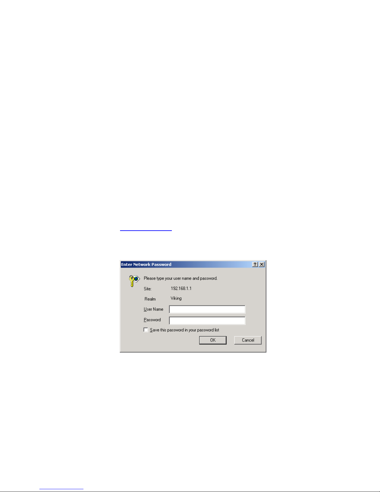
1. At any PC connected to the HM210dp/di, open a web browser, type
the following URL in the address (or location) box, and press
<Enter>:
http://192.168.1.1
2. When the Login screen appears, enter your User Name and
Password and then click OK:
The first time you launch the Configuration Manager, use these
default values:
Default User Name: root Default Password: root
3. After a successful login, the home page - System View - of the
Configuration Manager appears. See section 4.3 for further
information.
Page 19
Getting Started with the Configuration Manager
EN/LZT 108 6492 R2 - October 2003
11
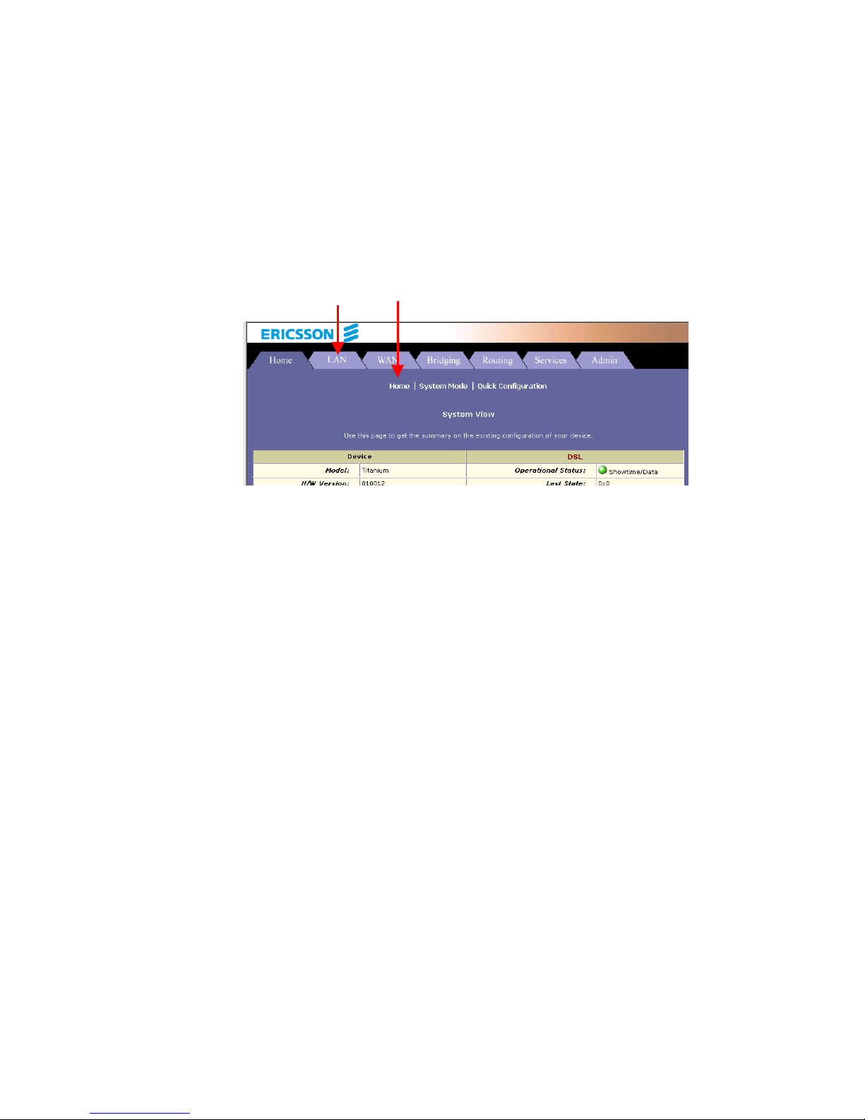
4.2 Functional Layout
The Configuration Manager tasks are grouped into categories, which you
can access by clicking the tabs at the top of each page. Each tab displays
the available tasks in a horizontal menu at the top of the page. You can
click on these menu items to display the specific configuration options.
A separate page displays for each task in the task bar. The left-most task
displays by default when you click on a new tab. The same task may
appear in more than one tab, when appropriate. For example, the LAN
Config task displays in both the LAN tab and the Routing tab.
Tab Task bar
Page 20

Getting Started with the Configuration Manager
12 EN/LZT 108 6492 R2 - October 2003
4.2.1 Commonly Used Buttons and Icons
The table below describes buttons and icons commonly used in the
Configuration Manager.
Button / Symbol Description
Stores in temporary system memory any changes you
have made on the current page. See section 4.4
“Committing Changes and Rebooting” for instructions
on how to store changes permanently.
Redisplays the current page with updated statistics or
settings.
When accumulated statistics are displaying, this button
resets the statistics to their initial value.
Launches the online help for the current topic in a
separate browser window. Help is available from any
main topic page.
Delete an entry.
Modify an entry.
View details for an entry.
Page 21
Getting Started with the Configuration Manager
EN/LZT 108 6492 R2 - October 2003
13
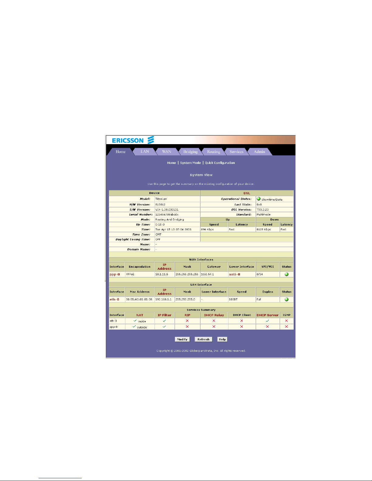
4.3 The Home Page and System View Table
The Home page - System View – displays when you first access the
Configuration Manager. This page is one of two options available in the
Home tab (the other is the Quick Configuration page, as described in
section 4.5).
The System View table provides a snapshot of your system configuration.
Note that some of the settings are links to the software pages that enable
you to configure those settings. The following table describes each section
of the System View table:
Page 22

Getting Started with the Configuration Manager
14 EN/LZT 108 6492 R2 - October 2003
Table Heading Description
Device Displays basic information about the HM210dp/di
hardware and software versions, the system uptime
(since the last reboot), and the preconfigured
operating mode.
DSL Displays the operational status, version, and
performance statistics for the DSL line. You can click
on DSL in the table heading or display the WAN tab to
view additional DSL settings, which are described in
chapter x.
WAN Interfaces Displays the software name(s) and various settings
for the device interface(s) that communicates with
your ISP via DSL. Although you only have one
physical DSL port, multiple software-defined
interfaces can be configured to use it.
For each interface, a “Lower Interface” name, such as
aal5-0, should display. You can click on the lower
interface name to view or change the ATM VC
settings that this interface uses.
LAN Interfaces Displays the software names and various settings for
the device interfaces that communicate directly with
your network. This typically includes an Ethernet
interface named eth-0.
Services Summary Displays the status of various services that the
HM210dp/di performs to help you manage your
network. A green ball indicates the service is active
and a red X indicates that it is inactive:
NAT – Translating private IP addresses to your public
IP address.
IP Filter – Setting up filtering rules that accept or deny
incoming or outgoing data.
RIP – Enabling router-to-router communication.
DHCP Relay – Enabling dynamic assignment of IP
information from your ISP to your computers.
DHCP Client – Enabling dynamic assignment of IP
information from your ISP or another computer on
your network to the device’s LAN port.
DHCP Server – Enabling dynamic assignment of IP
information from the device’s built-in DHCP server to
your LAN computers.
IGMP – Enabling message forwarding from external
sources such as your ISP, based on Internet Group
Management Protocol (not configurable).
Page 23
Getting Started with the Configuration Manager
EN/LZT 108 6492 R2 - October 2003
15
4.4 Commiting Changes and Rebooting
Whenever you change system settings, the changes are initially placed in a
temporary storage (called random access memory or RAM). Your changes
are made effective when you submit them, but will be lost if the device is
reset or turned off.
NOTE! Submitting changes activates them immediately, but saves
them only until the device is reset or powered down. Committing
changes saves them permanently.
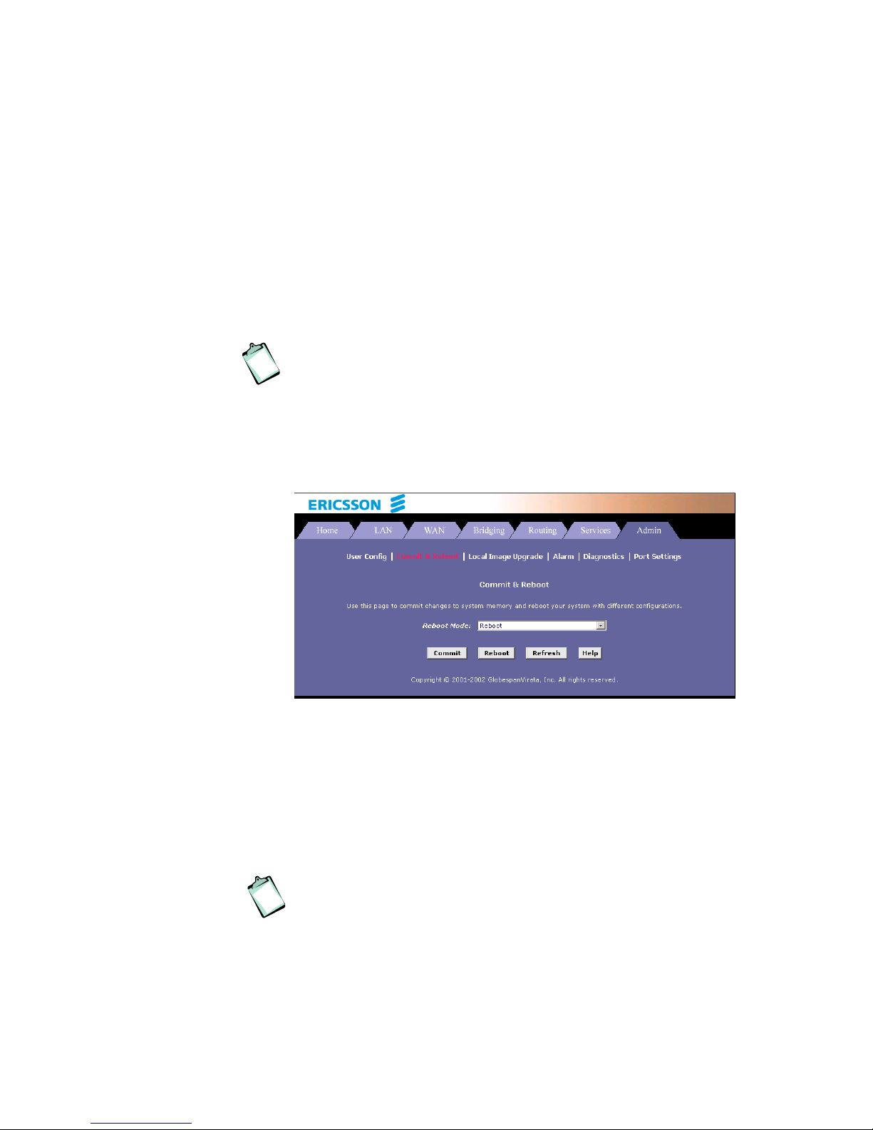
Follow these steps to commit changes to permanent storage:
1. Select Admin > Commit & Reboot. The Commit & Reboot page
appears:
2. Click the Commit button. (Disregard the selection in the Reboot
Mode: dropdown list, it does not affect the commit process).
The changes are saved to permanent storage.
The previous settings are copied to backup storage so that they can
be recalled if your new settings do not work properly (see the
rebooting instructions in section 4.4.1).
NOTE! If you change the LAN IP address information, you MUST
commit the changes and then reboot the system to activate them.
All other changes are activated when you commit them (no reboot
is needed).
Page 24

Getting Started with the Configuration Manager
16 EN/LZT 108 6492 R2 - October 2003
4.4.1 Rebooting the HM210dp/di using Options
If, after rebooting the device, you find that it does not operate properly with
the new configuration, you can reboot using options that reactivate a
previous configuration or the factory default configuration.
1. Select Admin > Commit & Reboot. The Commit & Reboot page
appears:
2. In the Reboot Mode: dropdown list you can select from the following
options before clicking the Reboot button.
Setting Description
Reboot Reboots the device to activate your new
settings (if any).
Reboot from Default
Configuration
Reboots the device to default settings provided
by your ISP or the manufacturer. Choosing this
option erases any custom settings.
Reboot from Backup
Configuration
Reboots the device using settings stored in
backup memory. These are the settings that
were in effect before you committed new
settings in the current session.
Reboot from Last
Configuration
Reboots the device using the current settings in
permanent memory, including any changes you
just committed.
Reboot from Clean
Configuration
Page 25

Getting Started with the Configuration Manager
EN/LZT 108 6492 R2 - October 2003
17
Reboot from Minimum
Configuration
NOTE! Do not reboot the device using the Reset button on the back
panel of the HM210dp/di to activate new changes. This button
resets the device settings to the manufacturer’s default values. Any
custom settings will be lost.
Page 26
Getting Started with the Configuration Manager
18 EN/LZT 108 6492 R2 - October 2003
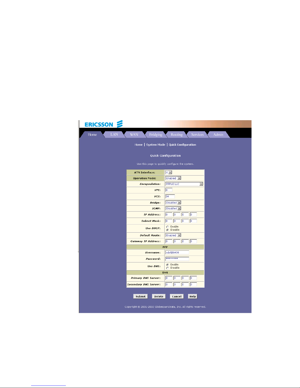
4.5 Quick Configuration
The Quick Configuration page allows you to quickly configure your
HM210dp/di for Internet connection. Your ISP should provide you with
necessary information to complete the quick setup.
To quickly configure the system, go to Home > Quick Configuration. The
Quick Configuration page appears:
Enter the provided fields as below:
Page 27

Getting Started with the Configuration Manager
EN/LZT 108 6492 R2 - October 2003
19
Field Description
ATM Interface: Select the ATM interface you want to use (usually
atm-0) for this connection.
Operation Mode: Enabled/Disabled.
If set to Disabled, the device cannot provide Internet
connectivity for your network.
Encapsulation:
Select the connection type your ISP uses to
communicate with your HM210dp/di.
VPI and VCI:
Enter the VPI/VCI values given by your ISP.
Bridge:
This setting enables or disables bridging between the
HM210dp/di and your ISP. Your ISP may also refer to
this using RFC 1483” or “Ethernet over ATM”.
IGMP:
This setting enables or disables the Internet Group
Management Protocol. Contact your ISP whether to
enable this setting.
IP Address: and
Subnet Mask:
If your ISP has assigned a public IP address to your
LAN, enter the IP address and associated subnet
mask in the boxes provided.
Use DHCP:
Select Enable if you want the HM210dp/di to act as a
DHCP server for your LAN.
Default Route:
When enabled, the IP address specified above will be
used as the default route for your LAN.
Gateway IP Address:
Specify the IP address that identifies the ISP server
through which your Internet connection will be routed.
PPP
Username:
Password:
If you select PPP as the Encapsulation type, enter the
Username and Password provided by your ISP.
Use DNS:
Select Enable to turn on the DNS forwarding service,
which forwards to your LAN PCs the DNS server
addresses that your PPP connection learns from your
ISP.
This option can only be used when the HM210dp/di
acts as a DHCP server for your LAN.
Page 28

Getting Started with the Configuration Manager
20 EN/LZT 108 6492 R2 - October 2003
Field Description
DNS
Primary/Secondary DNS
Server:
You may just keep the default 0.0.0.0.
If you enter the Primary/Secondary DNS addresses
given by your ISP, these DNS servers will be used in
addition to any DNS servers discovered automatically.
After completing the required settings, click the Submit button.
Then, go to Admin > Commit & Reboot and click the Commit button to
store your changes to permanent memory.
Page 29

Basic Configuration
EN/LZT 108 6492 R2 - October 2003
21
5 Basic Configuration
This chapter provides basic configuration instructions to get your
HM210dp/di run and have your network connected to the Internet.
The instructions assume that the HM210dp/di is not predefined with any
ATM VC, PPP or IpoA settings. For each connection method, example
parameters are given for your better understanding. You should consult
with your ISP to determine your connection mode and enter the actual
values provided by your ISP.
NOTE! Your HM210dp/di may already be pre-configured with the
necessary settings to get your network connected to the Internet.
Contact your ISP to determine whether you should change any
existing values.
5.1 Configuring the ATM Virtual Circuit
As your LAN computers access the Internet via the HM210dp/di, data is
exchanged with your ISP through a complex network of telephone
switches, Internet routers, servers, and other specialized hardware. These
various devices communicate using a common language, or protocol,
called Asynchronous Transfer Mode (ATM). On the Wide Area Network
(WAN) that connects you to your IPS, the ATM protocol performs functions
like those that the Ethernet protocol performs on your LAN.
This section describes how to configure the ATM Virtual Circuit (VC). The
VC properties define the path the HM210dp/di uses to communicate with
your ISP over the ATM network.
5.1.1 Adding ATM VCs
You may need to create a VC if none has been predefined on your system
or if you use multiple services with your ISP. Each service may require its
own VC.
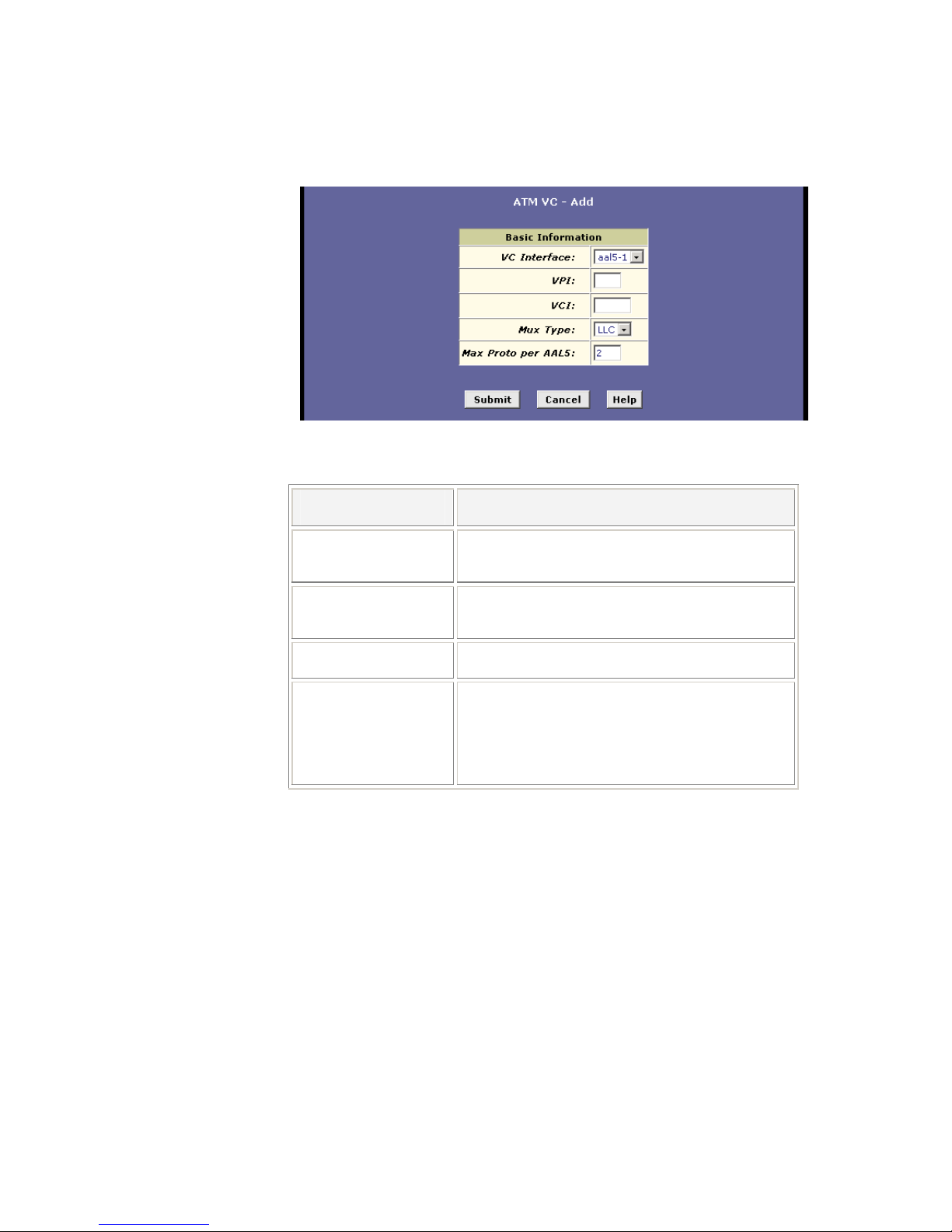
Follow these instructions to add an ATM VC Interface:
1. Select ATM > ATM VC to display the ATM VC Configuration page.
2. Click the Add button to display the ATM VC – Add page:
Page 30
Basic Configuration
22 EN/LZT 108 6492 R2 - October 2003
Enter the provided fields as below:
Field Description
VC Interface:
Select a VC interface from the available
interfaces, e.g. aal5-0.
VPI and VCI:
Enter the VPI/VCI values given by your ISP, e.g.
0/33.
Mux Type:
Select LLC or VC as required by your ISP.
Max Proto per AAL5:
This setting indicates the number of higher-level
interfaces that the VC can support (the higher
level interfaces can be PPP, EoA, or IpoA
interfaces). Contact your ISP to determine wich
connection protocol(s) they require.
3. After entering the fields above, click the Submit button and when
the confirmation page appears, click Close.
4. You will return to the ATM VC Configuration table and see the
newly added ATM VC entry:
Page 31

Basic Configuration
EN/LZT 108 6492 R2 - October 2003
23
5. Select Admin > Commit & Reboot and click the Commit button to
store your changes to permanent memory.
6. You may need to create a new WAN interface, or modify an existing
interface, so that it uses the new VC. See the instructions in the
following sections for configuring a PPP (section 5.2), EoA (section
5.3) or IpoA (section 5.4) interfaces, depending on the type you use
to communicate with your ISP.
5.1.2 Modifying ATM VCs
Your device may already be preconfigured with the necessary ATM VC
properties, or the table may contain placeholder values that you must
change before using the device. Contact your ISP to determine your ATM
VC values. Follow these instructions to modify a preconfigured VC:
1. From the ATM VC Configuration page, click
in the “Actions”
column for the interface you want to modify. The ATM VC Interface
– Modify page displays.
2. Enter the new VPI and VCI values, select the Mux Type, or change
the maximum number of protocols that the VC can carry, as
directed by your ISP.
You cannot modify the interface type over which an existing VC
operates (aal5-0, for example). If you want to change the interface
type, you must delete the existing interface, create a new one, and
select the desired interface type.
3. After entering the fields above, click the Submit button and when
the confirmation page appears, click Close.
4. Select Admin > Commit & Reboot and click the Commit button to
store your changes to permanent memory.
Page 32

Basic Configuration
24 EN/LZT 108 6492 R2 - October 2003
5.2 Configuring PPP Interfaces
When powered on, the HM210dp/di initiates a connection through your DSL
line to your ISP.
The Point-to-Point (PPP) protocol is commonly used between ISPs and
their customers to identify and control various communication properties,
including:
Identifying the type of service the ISP provides to a given customer.
Identifying the customer to the ISP through a username and
password login.
Enabling the ISP to assign Internet information to the customer’s
computers.
Your ISP may or may not use the PPP protocol. Contact your ISP to
determine if you will need to change the default settings in order to connect
to their server.
5.2.1 Adding PPP Interfaces
If you intend to use more than one type of service from your ISP, the device
can be configured with multiple PPP interfaces, each with unique logon and
other properties.
Follow this procedure to define properties for a PPP interface:
1. Select WAN > PPP to display the Point to Point Protocol (PPP)
Configuration page.
Page 33
Basic Configuration
EN/LZT 108 6492 R2 - October 2003
25
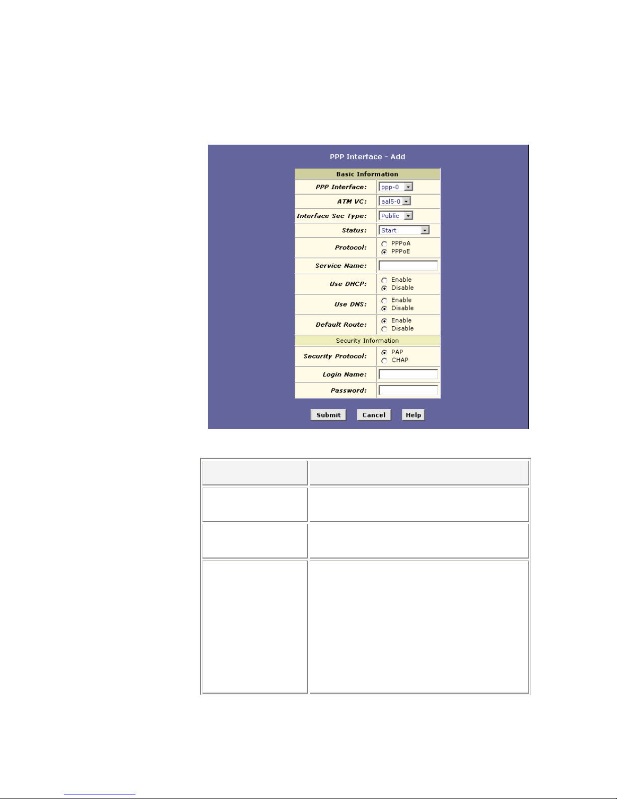
2. Click the Add button to display the PPP Interface – Add page:
3. Enter the provided fields as below:
Field Description
PPP Interface:
Select a PPP interface from the available
interfaces, e.g. ppp-0.
ATM VC:
Select the ATM VC you wish to use for this
connection, e.g. aal5-0.
Interface Sec Type:
Public / Private / DMZ.
This setting defines the type of firewall
protections that are in effect on the interface as
described below:
A public interface connects to the Internet (PPP
interfaces are typically public). Packets received
on a public interface are subject to the most
restrictive set of firewall protections defined in the
software.
Page 34

Basic Configuration
26 EN/LZT 108 6492 R2 - October 2003
A private interface connects to your LAN, such
as the Ethernet interface. Packets received on a
private interface are subject to a less restrictive
set of protections, because they originate within
the network.
The term DMZ (de-militarized zone), in Internet
networking terms, refers to computers that are
available for both public and in-network accesses
(such as a company’s public Web server).
Packets incoming on a DMZ interface – whether
from a LAN or external source – are subject to a
set of protections that is in between public and
private interfaces in terms of restrictiveness.
Status:
Start – To establish a connection whenever you
turn on the HM210dp/di.
StartOnData – To establish a connection
whenever the device gets a request to connect to
the Internet, such as when you open a browser
requesting for web pages.
Protocol:
PPPoA or PPPoE as required by your ISP.
Service Name:
ISPs may offer different types of services (for
example, for online gaming or business
communications), each requiring a different login
and other connection properties.
For PPPoA no need to set up.
For PPPoE enter the Service Name if this is
required by your ISP. Otherwise leave it blank.
Use DHCP:
When set to Enable, the device will acquire
additional IP information from the ISP’s DHCP
server. The PPP connection itself acquires the
device’s IP address, mask, DNS address, and
default gateway address. When enabled, the
device will acquire IP addresses for various other
server types (WINS, SMTP, POP3, etc).
Use DNS:
When set to Enable, the DNS address learned
through the PPP connection will be distributed to
clients of the device’s DHCP server. This option
is useful only when the HM210dp/di is configured
to act as a DHCP server for your LAN.
Default Route:
Indicates whether the HM210dp/di should use
the IP address assigned to this connection as its
default route.
Page 35
Basic Configuration
EN/LZT 108 6492 R2 - October 2003
27
Security Information
Security Protocol:
Select PAP or CHAP as required by your ISP.
Login Name:
Password:
The login name and password given by your ISP.
NOTE that characters of colon (:), semicolon (;)
and questions mark (?) are not allowed when
entering login name and password.
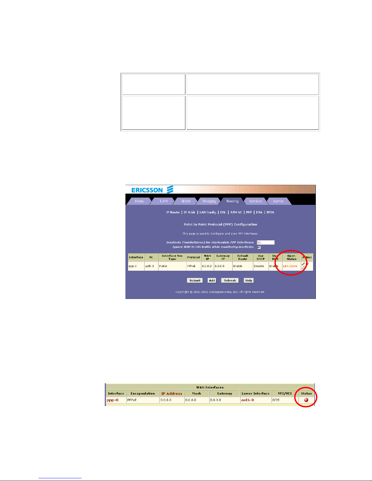
5. After entering the fields above, click the Submit button and when
the confirmation page appears, click Close.
6. You will return to the PPP Configuration page and see the newly
added PPP interface. The “Oper. Status” column indicates if the link
is currently up or down:
7. Select Admin > Commit & Reboot and click the Commit button to
store your changes to permanent memory.
5.2.2 Checking Your Connection Status
Select Home > System Mode. The “WAN Interface” item should display
the interface you created to communicate with your ISP. A green ball in the
“Status” field indicates a successful connection:
Page 36

Basic Configuration
28 EN/LZT 108 6492 R2 - October 2003
5.2.3 Modifying and Deleteing PPP Interfaces
To modify a PPP interface, display the PPP Configuration page and click
in the “Action(s)” column for the interface you want to modify. The PPP
Interface – Modify page displays.
You can change only the status of the PPP connection, the security
protocol, your login name and your password. To modify the other settings,
you must delete the interface and create a new one.
To delete a PPP interface, display the PPP Configuration page and click
in the “Action(s)” column for the interface you want to delete. You should
not delete a PPP interface unless you have received instructions to do so
from your ISP. Without an appropriately defined PPP interface, you may not
be able to connect to your ISP. You can recreate the PPP interface with the
same name at a later time.
After modifying or deleting a PPP interface, click the Submit button. Then
select Admin > Commit & Reboot and click the Commit button to save
your changes to permanent memory.
Page 37

Basic Configuration
EN/LZT 108 6492 R2 - October 2003
29
5.3 Configuring EoA Interfaces
This section describes how to configure an Ethernet-over-ATM interface on
the HM210dp/di, if one is needed to communicate with your ISP.
The Ethernet-over-ATM (EoA) protocol is often referred to as RFC1483,
which is the Internet specification that defines it. It is commonly used to
carry data between local area networks that use the Ethernet protocol and
wide-area networks that use the ATM protocol. Many telecommunications
industry networks use the ATM protocol. ISPs who provide DSL services
often use the EoA protocol for data transfer with their customers’ DSL
modems.
EoA can be implemented to provide a bridged connection between a DSL
modem and the ISP. In a bridged connection, data is shared between the
ISP’s network and their customer’s as if the networks were on the same
physical LAN. Bridged connections do not use the IP protocol. EoA can
also be configured to provide a routed connection with the ISP, which uses
the IP protocol to exchange data.
Before creating an EoA interface or modifying the default settings, contact
your ISP to determine which type of protocol they use.
5.3.1 Adding EoA Interfaces
Follow these instructions to add an EoA interface:
1. Select WAN > EoA to display the RFC1483/Ethernet over
ATM(EoA) Configuration page.
Page 38
Basic Configuration
30 EN/LZT 108 6492 R2 - October 2003
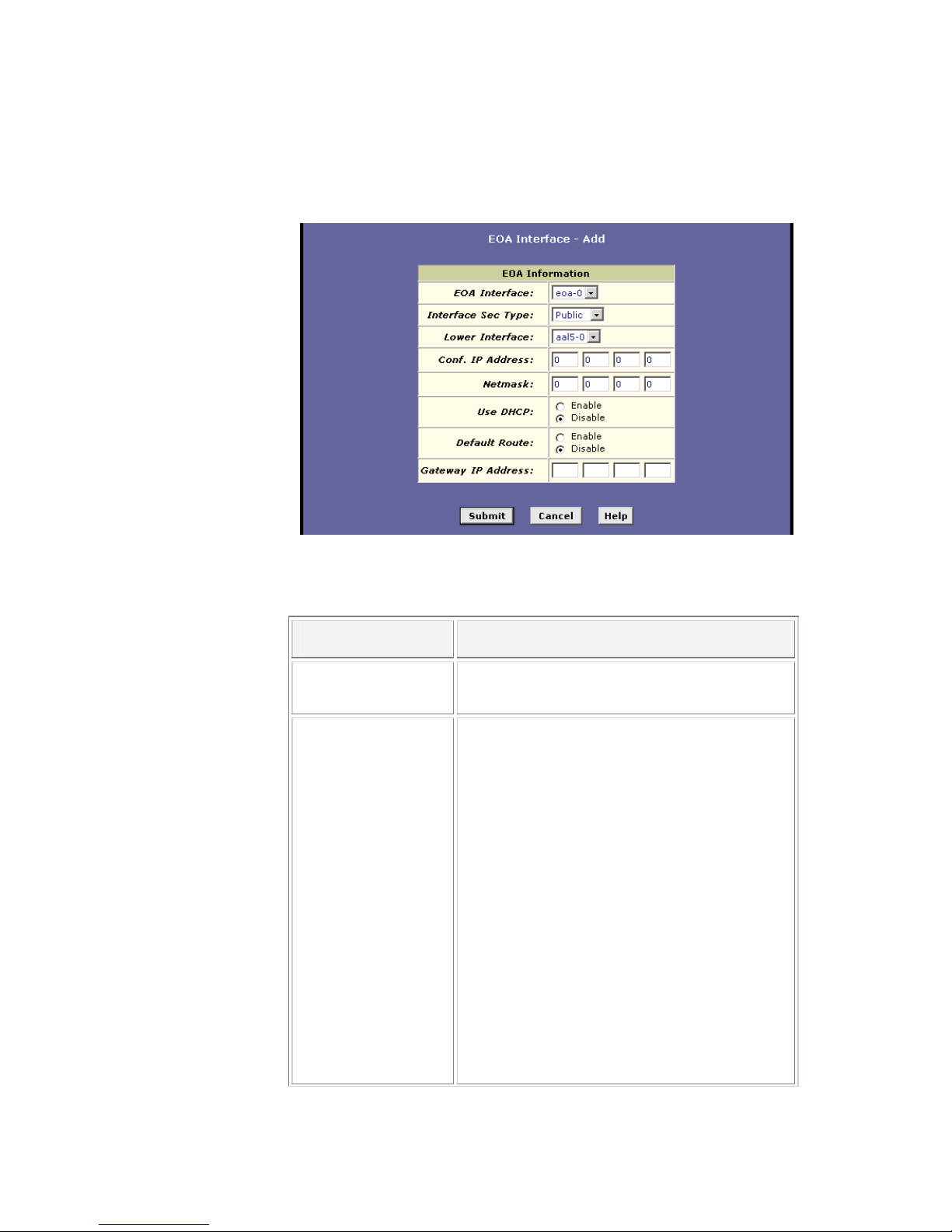
2. Click the Add button to display the EOA Interface – Add page:
3. Enter the provided fields as below:
Field Description
EOA Interface:
Select an EoA interface from the available
interfaces, e.g. eoa-0.
Interface Sec Type:
Public / Private / DMZ.
This setting defines the type of firewall
protections that are in effect on the interface as
described below:
A public interface connects to the Internet (PPP
interfaces are typically public). Packets received
on a public interface are subject to the most
restrictive set of firewall protections defined in the
software.
A private interface connects to your LAN, such
as the Ethernet interface. Packets received on a
private interface are subject to a less restrictive
set of protections, because they originate within
the network.
The term DMZ (de-militarized zone), in Internet
networking terms, refers to computers that are
available for both public and in-network accesses
Page 39

Basic Configuration
EN/LZT 108 6492 R2 - October 2003
31
(such as a company’s public Web server).
Packets incoming on a DMZ interface – whether
from a LAN or external source – are subject to a
set of protections that is in between public and
private interfaces in terms of restrictiveness.
Lower Interface:
Select an ATM VC interface previously created,
e.g. aal5-0.
EoA interfaces are defined in software, and then
associated with lower-level software and
hardware structures (at the lowest level, they are
associated with a physical port – the WAN port).
This field should reflect an interface name
defined in the next lower level of software over
which the EoA interface will operate.
Conf. IP Address:
Netmask:
0.0.0.0 / 0.0.0.0
To use the HM210dp/di as a bridge, you don’t
need to set the IP address and subnet mask.
Just keep the default.
Use DHCP: Enable / Disable
When Enabled, this setting instructs the device
to accept IP information assigned dynamically by
your ISP’s DHCP server. If the interface will be
used for bridging with your ISP and you will not
be routing data through it, leave this checkbox
unselected.
Default Route: Enable / Disable
Indicates whether the HM210dp/di uses the IP
address assigned to this interface, if any, as its
default route for your LAN. Your system can have
only one default route.
Gateway IP Address:
The external IP address that the HM210dp/di
communicates with via the EoA interface to gain
access to the Internet. This is typically an ISP
server.
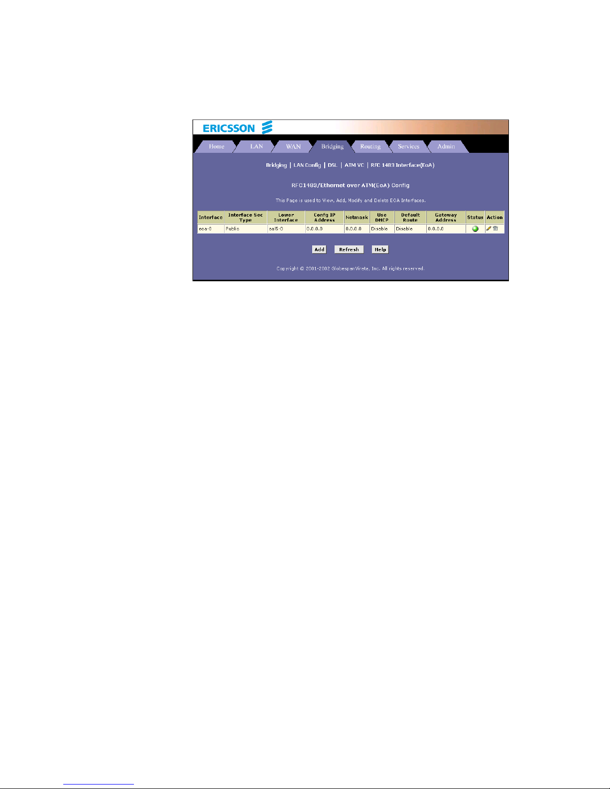
4. After entering the fields above, click the Submit button and when
the confirmation page appears, click Close.
5. You will return to the EoA Configuration page and see the newly
added EoA interface:
Page 40
Basic Configuration
32 EN/LZT 108 6492 R2 - October 2003
6. Select Admin > Commit & Reboot and click the Commit button to
store your changes to permanent memory.
Page 41

Basic Configuration
EN/LZT 108 6492 R2 - October 2003
33
5.4 Configuring IPoA Interfaces
This section describes how to configure an IPoA (Internet Protocol-overATM) interface on the HM210dp/di.
An IPoA interface can be used to exchange IP packets over the ATM
network, without using an underlying Ethernet over ATM (EoA) connection.
Typically, this type of interface is used only in product development and test
environments, to eliminate unneeded variables when evaluating IP layer
processing.
5.4.1 Adding IPoA Interfaces
Follow these instructions to add an IPoA interface:
1. Select WAN > IPoA to display the IPoA Configuration page.
2. Click the Add button to display the IPoA Interface – Add page:
3. Enter the provided fields as below:
Field Description
IPoA Interface:
Select an IPoA interface from the available
interfaces, e.g. ipoa-0.
Conf. IP Address:
Enter the IP address given by your ISP.
Page 42

Basic Configuration
34 EN/LZT 108 6492 R2 - October 2003
Interface Sec Type:
Public / Private / DMZ.
This setting defines the type of firewall
protections that are in effect on the interface as
described below:
A public interface connects to the Internet (PPP
interfaces are typically public). Packets received
on a public interface are subject to the most
restrictive set of firewall protections defined in the
software.
A private interface connects to your LAN, such
as the Ethernet interface. Packets received on a
private interface are subject to a less restrictive
set of protections, because they originate within
the network.
The term DMZ (de-militarized zone), in Internet
networking terms, refers to computers that are
available for both public and in-network accesses
(such as a company’s public Web server).
Packets incoming on a DMZ interface – whether
from a LAN or external source – are subject to a
set of protections that is in between public and
private interfaces in terms of restrictiveness.
Netmask:
Enter the IP address given by your ISP.
RFC 1577:
Specifies whether the IPoA protocol to be used
complies with the IEFT specification named “RFC
1577 – Classical IP and ARP over ATM”. Select
Yes for RFC 1577-Classical IP and ARP over
ATM.
Select No for RFC 1483 Router.
Use DHCP: Enable / Disable
When Enabled, this setting instructs the device
to accept IP information assigned dynamically by
your ISP’s DHCP server. If the interface will be
used for bridging with your ISP and you will not
be routing data through it, leave this checkbox
unselected.
Default Route: Enable / Disable
Indicates whether the HM210dp/di uses the IP
address assigned to this interface, if any, as its
default route for your LAN. Your system can have
only one default route.
Gateway IP Address:
Enter the gateway IP address given by your ISP.
Page 43

Basic Configuration
EN/LZT 108 6492 R2 - October 2003
35
4. After entering the fields above, click the Submit button and when
the confirmation page appears, click Close.
5. You will return to the IpoA Configuration table and see the newly
added IPoA entry:
6. Click Map in the “Action” column. The IPoA Interface – Map page
appears:
7. Select an ATM VC you have created earlier from the “Lower
Interface:” dropdown list and then click Add. Click Close to exit the
confirmation page.
8. Select Admin > Commit & Reboot and click the Commit button to
store your changes to permanent memory.
5.4.2 Checking Your Connection Status
Select Home > System Mode. The WAN Interface item should display the
interface you created to communicate with your ISP. A green ball in the
Status field indicates a successful connection:
Page 44

Basic Configuration
36 EN/LZT 108 6492 R2 - October 2003
5.5 Bridging Connection Mode
The HM210dp/di can be configured to act as a bridging device between
your LAN and your ISP. Bridges are devices that enable two or more
networks to communicate as if they are two segments of the same physical
LAN.
Although the HM210dp/di is preconfigured to serve as router for providing
Internet connectivity to your LAN, there are several instances in which you
may also want to configure bridging:
Your ISP may use protocols that require bridging with your LAN.
The device can be configured to appear as a bridge when
communicating with your ISP, while continuing to provide router
functionality for your LAN.
Your LAN may include computers that communicate using “layer-3”
protocols other than the Internet Protocol. These include IPX and
AppleTalk. In this case, the device can be configured to act as a
bridge for packets that use these protocols while continuing to serve
as a router for IP data.
5.5.1 Defining Bridge Interfaces
To enable bridging, you simply specify the device interfaces on which you
want to bridge data, and then enable bridging mode.
Follow the steps below to enable bridging mode:
1. Select Bridging > Bridging page to display the Bridge
Configuration page.
2. Select the interface names on which you ant to perform bridging
and click the Add button.
If you do not have an eoa-0 interface, but instead have an interface
named ppp-0 or ipoa-0, your device is not currently configured with
a WAN interface that allows bridging with your ISP. Check with your
ISP to determine whether they use the eoa protocol before
changing this setting.
3. Click the Bridging: Enable radio button to turn on bridging and click
the Submit button. A page will briefly display to confirm your
changes, and will return you to the Bridge Configuration page.
4. Select Admin > Commit & Reboot and click the Commit button to
store your changes to permanent memory.
Page 45

Basic Configuration
EN/LZT 108 6492 R2 - October 2003
37
5.5.2 Check Your Connection Status
Select Home > System Mode. The WAN Interface item should display the
interface you created to communicate with your ISP. A green ball in the
Status field indicates a successful connection:
5.5.3 Deleting a Bridge Interface
To make an interface non-bridgeable, display the Bridge Configuration
page and click
next to the interface you want to delete.
Click OK to confirm the deletion.
The interface remains defined in the system, but is no longer capable of
performing bridging.
Page 46

Configuring IP Routes
38 EN/LZT 108 6492 R2 - October 2003
6 Configuring IP Routes
You can use the Configuration Manager to define specific routes for your
Internet and network data. This chapter provides instructions for creating
routes.
Most users do not need to define IP routes. On a typical small home or
office LAN, the existing routes that set up the default gateways for your
LAN computers and for the HM210dp/di provide the most appropriate path
for all your Internet traffic. You may need to define routes if:
Your network setup includes two or more networks or subnets.
You connect to two or more ISP services.
You connect to a remote corporate LAN.
6.1 Overview of IP Routes
The essential challenge of a router is: when it receives data intended for a
particular destination, which next device should it send that data to? When
you define IP routes, you provide the rules that a computer uses to make
these decisions.
Each time Internet data is passed from one Internet address to another, it is
said to take a hop. A hop can be a handoff to a different port on the same
device, to a different device on the same network, or to a device on an
entirely different network.
When a hop passes data from one type of network to another, it uses a
gateway. A gateway is an IP address that provides initial access to a
network, just as a switchboard serves as a gateway to a specific set of
phone numbers. For example, when a computer on your LAN requests
access to a company’s web site, your ISP serves as a gateway to the
Internet. As your request reaches its destination, another gateway provides
access to the company’s web servers.
IP routes are defined on computers, routers, and other IP-enabled devices
to instruct them which hop to take, or which gateway to use, to help forward
data along to its specified destination.
If no IP route is defined for a destination, then IP data is passed to a
predetermined default gateway. The default gateway serves like a higher-
level telephone switchboard; it may not be able to connect directly to the
destination, but it will know a set of other devices that can help pass the
Page 47

Configuring IP Routes
EN/LZT 108 6492 R2 - October 2003
39
data intelligently. If it cannot determine which of these devices provides a
good next hop (because no such route has been defined), then that device
will forward the data to its default gateway. Eventually, a high level device,
using a predefined IP route, will be able to forward the data along a path to
its destination.
6.2 Viewing the IP Routing Table
All IP-enabled computers and routers maintain a table of IP addresses that
are commonly accessed by their users. For each of these destination IP
addresses, the table lists the IP address of the first hop the data should
take. This table is known as the device’s routing table.
To view the HM210dp/di routing table, select Routing > IP Route. The
following page appears:
The IP Route Table displays a row for each existing route. These include
routes that were predefined on the device, routes you may have added,
and routes that the device has identified automatically through
communication with other devices.
The routing table should reflect a default gateway, which directs outbound
Internet traffic to your ISP. This default gateway is shown in the row
containing destination address 0.0.0.0.
The following table defines the fields in the IP Routing table:
Page 48

Configuring IP Routes
40 EN/LZT 108 6492 R2 - October 2003
Field Description
Destination:
Specifies the IP address of the destination
computer. The destination can be specified as
the IP address of a specific computer or an entire
network. It can also be specified as all zeros to
indicate that this route should be used for all
destinations for which no other route is defined
(this is the route that creates the default
gateway).
Netmask:
Indicates which parts of the destination address
refer to the network and which parts refer to a
computer on the network. The default gateway
uses a netmask of 0.0.0.0.
NextHop
Specifies the next IP address to send data to
when its final destination is that shown in the
destination column.
IFName:
Displays the name of the interface on the device
through which data is forwarded to the specified
next hop.
Route Type:
Displays whether the route is direct or indirect. In
a direct route, the source and destination
computers are on the same network, and the
router attempts to directly deliver the data to the
computer.
In an indirect route, the source and destination
computers are on different networks, and the
router forwards data to a device on another
network for further handling.
Route Origin:
Displays how the route was defined. Dynamic
indicates that the route was created automatically
or predefined by your ISP or the manufacturer.
Routes you create are labeled Local. Other
routes can be created automatically (using RIP),
or defined remotely through various network
management protocols (LCL or ICMP).
Action:
Displays and icon (
) you can click to delete a
route.
Page 49
Configuring IP Routes
EN/LZT 108 6492 R2 - October 2003
41
6.3 Adding IP Routes
To add an IP route to the routing table, follow the steps below:
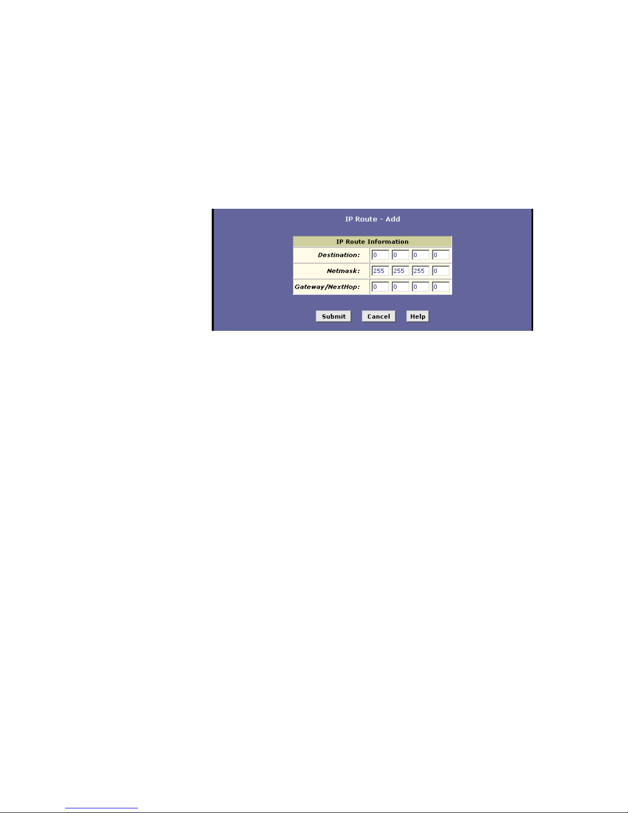
1. Select Routing > IP Route > Add. The IP Route – Add page
appears:
2. Specify the destination, netmask, and gateway or next hop for this
route. For a description of these fields, refer to the table on the
previous page.
To create a route that defines the default gateway for your LAN,
enter 0.0.0.0 in both the Destination and Netmask fields. Enter
your ISP’s IP address in the Gateway/NextHop field.
NOTE! You cannot specify the interface name, route type or route
origin. These parameters are used only for routes that are identified
automatically as the device communicates with other routing
devices. For routes you create, the routing table displays system
default values in these fields.
3. Click the Submit button. The IP routing Table will now display the
new route.
4. Select Admin > Commit & Reboot and click the Commit button to
save your changes to permanent storage.
Page 50

Configuring DHCP
42 EN/LZT 108 6492 R2 - October 2003
7 Configuring DHCP
You can configure your network and HM210dp/di to use the Dynamic Host
Configuration Protocol (DHCP). This chapter provides instructions for
implementing DHCP on your network.
7.1 Overview of DHCP
DHCP is a protocol that enables network administrators to centrally
manage the assignment and distribution of IP information to computers on
a network.
When you enable DHCP on a network, you allow a device – such as the
HM210dp/di or a router located with your ISP – to assign temporary IP
addresses to your computers whenever they connect to your network. The
assigning device is called a DHCP Server and the receiving device is a
DHCP Client.
The DHCP server draws from a defined pool of IP addresses and “leases”
them for a specified amount of time to your computers when they request
an Internet session. It monitors, collects, and redistributes the addresses as
needed.
On a DHCP-enabled network, the IP information is assigned dynamically
rather than statically. A DHCP client can be assigned a different address
from the pool each time it reconnects to the network.
DHCP allows you to manage and distribute IP addresses throughout your
network from a central computer. Without DHCP, you would have to
configure each computer separately with IP addresses and related
information. DHCP is commonly used with large networks and those that
are frequently expanded or otherwise updated
7.2 DHCP Modes
The HM210dp/di can be configured as a DHCP server, DHCP relay agent,
or in some cases, a DHCP client.
DHCP Server
The HM210dp/di will maintain the pool of addresses and distribute
them to your LAN computers. If the pool of addresses includes
private IP addresses, you must also configure the Network Address
Translation (NAT) service, so that the private addresses can be
Page 51

Configuring DHCP
EN/LZT 108 6492 R2 - October 2003
43
translated to your public IP address on the Internet. Both DHCP
server and NAT are enabled in the default configuration.
DHCP Relay Agent
If your ISP performs the DHCP server function for your network,
then you can configure the HM210dp/di as a DHCP relay agent.
When the HM210dp/di receives a request for Internet access from a
computer on your network, it contacts your ISP for the necessary IP
information, and then relays the assigned information back to the
computer.
DHCP Client
If you have another PC or device on your network that is already
performing the DHCP server function, you can configure the LAN
port on the HM210dp/di to be a DHCP client of that server.
NOTE! Your can input settings for both DHCP server and DHCP
relay mode, and then activate either mode at any time. Deactivated
settings are retained for your future use.
7.3 Configuring DHCP Server
To set up DHCP server, you first define the ranges of IP addresses that you
want to be distributed to your PCs, called DHCP server address pools.
IP address pools can contain multiple public addresses that you have
purchased from your ISP, but are typically private addresses that you
create. LAN administrators often create private IP addresses for use only
on their networks. See “Overview of NAT” for an explanation of private IP
addresses.
You can create up to two pools and the pools can maintain a combined
total of 254 IP addresses. For example, you could configure only one pool
with addresses in the range 192.168.1.2 through 192.168.1.255, or two
pools with the following address range:
Pool 0: 192.168.1.2 through 192.168.1.128
Pool 1: 192.168.1.129 through 192.168.1.255
You may want to create a second pool if any of these circumstances apply:
Your LAN configuration includes two subnets.
You have only one subnet, but the addresses you want to distribute
are not in a continuous range.
Page 52
Configuring DHCP
44 EN/LZT 108 6492 R2 - October 2003
7.3.1 Creating DHCP Server Address Pools
To create a pool of IP addresses follow the steps below:
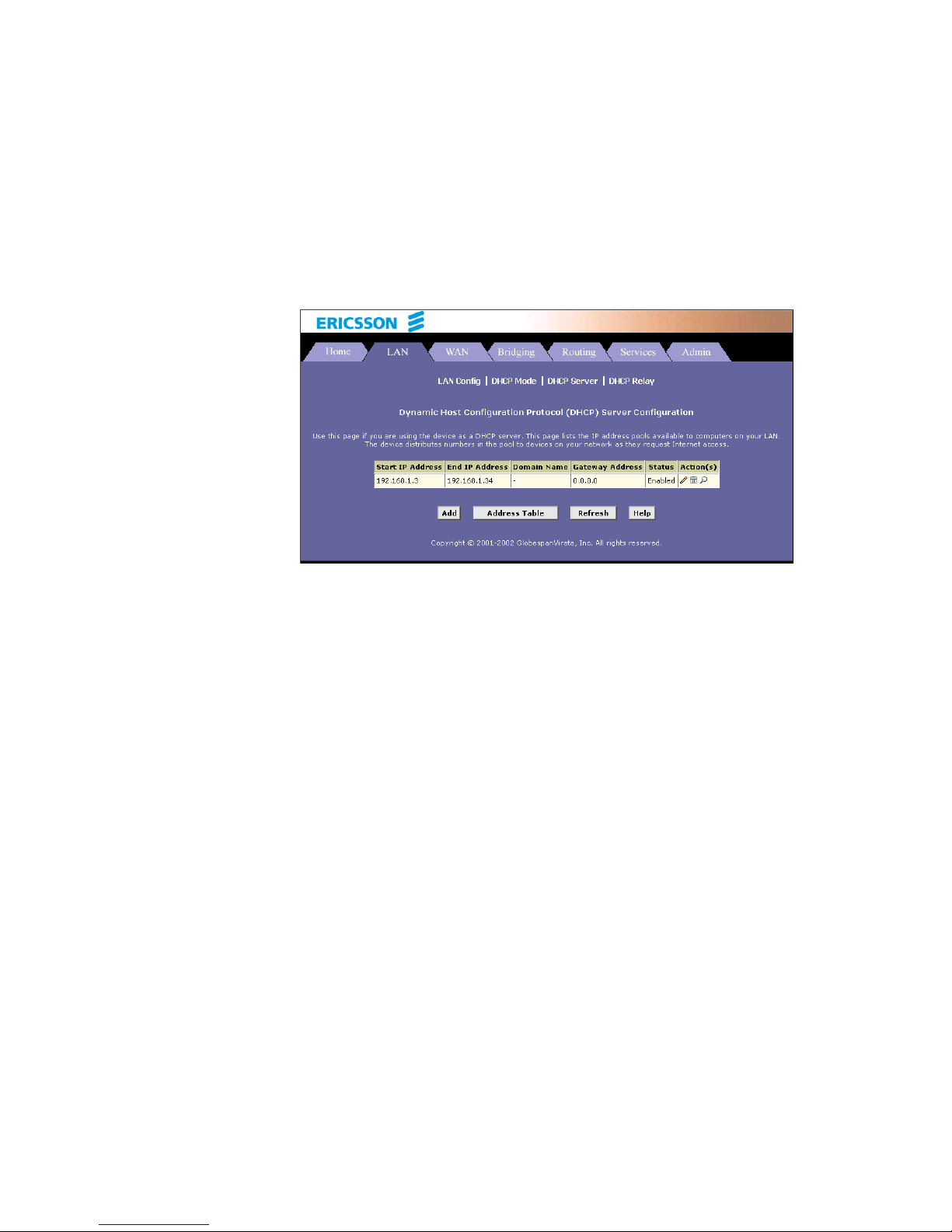
1. Select LAN > DHCP Server. The DHCP Server Configuration
page appears:
Depending on your preconfigured settings, the table may display
one or more address pools, each in a row, or may be empty.
2. To add an IP address pool, click Add. The DHCP Server Pool –
Add page appears:
Page 53

Configuring DHCP
EN/LZT 108 6492 R2 - October 2003
45
Enter the provided fields as below:
The Start IP Address, End IP Address, Net Mask and Gateway
Address fields are required, the others are optional.
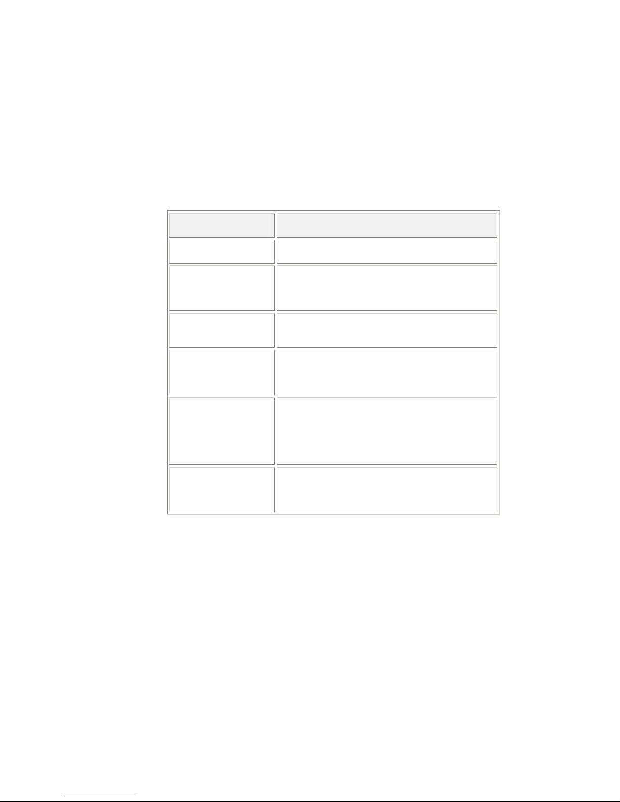
Field Description
Start IP Address:
End IP Address:
Specify the lowest and highest IP addresses in
the pool, up to a maximum range of 254
addresses. For example, if the LAN port is
assigned IP address 192.168.1.1, then you could
create a pool with address range 192.168.1.2 –
192.168.1.254 for distribution to your LAN
computers.
Mac Address:
A MAC address is a manufacturer-assigned
hardware ID that is unique for each device on a
network. Use this field only if you want to assign
a specific IP address to the computer that uses
this MAC address. If you type a MAC address
here, you must have specified the same IP
Page 54

Configuring DHCP
46 EN/LZT 108 6492 R2 - October 2003
address in both the Start/End IP Address fields.
Netmask:
Specifies which portion of each IP address in this
range refers to the network and which portion
refers to the host (computer). You can use the
network mask to distinguish which pool of
addresses should be distributed to a particular
subnet.
Domain Name:
A user-friendly name that refers to the subnet
that includes the addresses in this pool. This is
used for reference only.
Gateway Address:
The address of the default gateway for
computers that receive IP addresses from this
pool. If no value is specified, then the appropriate
LAN (eth-0) port address on the device will be
distributed to each PC as its gateway address.
DNS/SDNS Address:
The IP address of the Domain Name System
server and Secondary Domain Name System
server to be used by computers that receive IP
addresses from this pool. These DNS servers
translate common Internet names that you type
into your web browser into their equivalent
numeric IP addresses. Typically, these servers
are located with your ISP.
SMTP … SWINS
Address: (optional)
The IP addresses of devices that perform various
services for computers that receive IP addresses
from this pool (such as the SMTP, or Simple Mail
Transfer Protocol, server which handles e-mail
traffic). Contact your ISP for these addresses.
3. Click the Submit button. A confirmation page appears briefly to
indicate that the pool has been added successfully. After a few
seconds, the DHCP Server Pool – Add page displays with the
newly added pool.
4. Follow the instructions in the next section to enable the DHCP
Server mode.
7.3.2 Enabling DHCP Server Mode
To enable the DHCP server mode follow the steps below:
1. Select LAN > DHCP Mode and from the “DHCP Mode” dropdown
list select DHCP Server. Click the Submit button.
Page 55

Configuring DHCP
EN/LZT 108 6492 R2 - October 2003
47
2. A page appears to confirm the change.
3. Select Admin > Commit & Reboot and click the Commit button to
save your changes to permanent storage.
7.3.3 Configuring Your PCs as DHCP Clients
For each computer that you want to configure to receive IP information
automatically, configure the TCP/IP properties to “Obtain an IP address
automatically” (the actual text may vary depending on your operating
system). Refer to section 3.1 “Configuring your PCs as DHCP Clients” for
detailed instructions.
7.3.4 Viewing, Modifying and Deleting Address Pools
To view, modify, or delete an existing address pool, display the DHCP
Service Configuration page, and click the icons (in the “Action(s)”) column
for the corresponding row in the address pool table.
To delete an IP address pool, click , then submit and commit your
changes.
To view details on an IP address pool, click . A page displays
with the same information that you entered when you added the
pool.
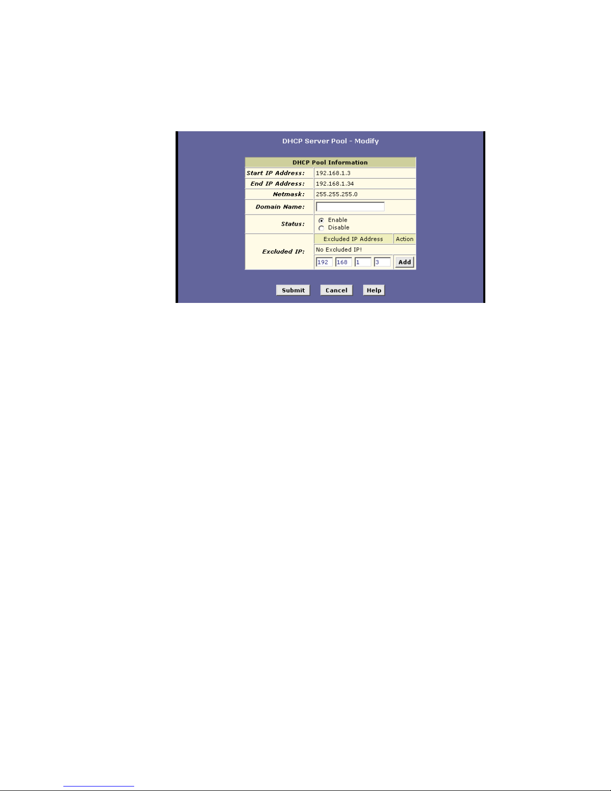
To modify the pool, click . The DHCP Server Pool – Modify
page displays:
Page 56
Configuring DHCP
48 EN/LZT 108 6492 R2 - October 2003
When modifying an IP address pool, you are only allowed to:
Change the domain name associated with the pool and to exclude
IP addresses within its range from distribution. To exclude an IP
address, enter it in the field provided and click Add.
If you want to change other attributes, you must delete the pool and
create a new one.
After entering your changes, click the Submit button.
Select Admin > Commit & Reboot and click the Commit button to save
your changes to permanent storage.
7.3.5 Excluding IP Addresses from a Pool
If you have IP addresses that are designated for fixed use with specific
devices, or for some other reason you do not want to make them available
to your network, you can exclude them from the pool.
Display the DHCP Server Pool – Modify page. Type each address to be
excluded in the “Excluded IP:” field and click Add. When you are done
specifying excluded addresses, click the Submit button.
Select Admin > Commit & Reboot and click the Commit button to save
your changes to permanent storage.
7.3.6 Viewing Current DHCP Address Assignments
When the HM210dp/di functions as a DHCP server for your LAN, it keeps a
record of any addresses currently leased to your computers.
Page 57
Configuring DHCP
EN/LZT 108 6492 R2 - October 2003
49
To view a table of all current IP address assignments, select LAN > DHCP
Server and on that page click the Address Table button to view the DHCP
Server Address Table page.
For each leased address, the table lists the following information:
Field Description
IP Address:
The address that has been leased from the pool.
Netmask:
The network mask associated with the leased
address. This identifies the network ID and host
ID portions of the address.
Mac Address:
The unique hardware ID of the computer to which
the IP address has been assigned.
Pool Start:
The lower boundary of the address pool (shown
here to identify the pool from which the leased
address was assigned).
Address Type:
Can be Static or Dynamic. Static indicates that
the IP address has been assigned permanently
to the specific hardware device. Dynamic
indicates that the IP address has been leased
temporarily for a specified length of time.
Time Remaining:
The amount of time left for the device to use the
assigned address. The default lease time is 30
days (31536000 seconds).
7.4 Configuring DHCP Relay
Some ISPs perform the DHCP server function for their customers’
home/small office networks. In this case, you can configure the device as a
DHCP relay agent. When a computer on your network requests Internet
access, the HM210dp/di contacts your ISP to obtain an IP address (and
other information), and then forwards that information to the computer.
7.4.1 Defining the DHCP Relay Interface(s)
To define the DHCP Relay interface(s) follow the steps below:
Page 58

Configuring DHCP
50 EN/LZT 108 6492 R2 - October 2003
1. Select LAN > DHCP Relay. The DHCP Relay Configuration page
appears:
This page provides a text box for entering the IP address of your
ISP’s DHCP server and a table that lists the interfaces on your
HM210dp/di that can relay DHCP information.
2. Type the IP address of your ISP’s DHCP server in the fields
provided.
If you do not have this address, it is not essential to enter it.
Requests for IP information from your LAN will be passed to the
default gateway, which should route the request appropriately.
3. If the interface named eth-0 is not already displaying, select it from
the dropdown list and click Add in the “Action” column.
4. Click the Submit button. A page appears to confirm your changes
and then the program returns to the DHCP Relay Configuration
page.
5. Follow the instructions in the next section to enable the DHCP
Relay mode.
7.4.2 Enabling DHCP Relay Mode
To enable the DHCP relay mode follow the steps below:
1. Select LAN > DHCP Mode and from the “DHCP Mode” dropdown
list select DHCP Relay. Click the Submit button.
Page 59

Configuring DHCP
EN/LZT 108 6492 R2 - October 2003
51
2. A page appears to confirm the change.
3. Select Admin > Commit & Reboot and click the Commit button to
save your changes to permanent storage.
7.4.3 Configuring Your PCs as DHCP Clients
For each computer that you want to configure to receive IP information
automatically, configure the TCP/IP properties to “Obtain an IP address
automatically” (the actual text may vary depending on your operating
system). Refer to section 3.1 “Configuring your PCs as DHCP Clients” for
detailed instructions.
Page 60

Configuring NAT
52 EN/LZT 108 6492 R2 - October 2003
8 Configuring NAT
This chapter provides an overview of Network Address Translation (NAT)
and instructions for modifying the default configuration on your
HM210dp/di.
8.1 Overview of NAT
Network Address Translation is a method for disguising the private IP
addresses you use on your LAN as the public IP address you use on the
Internet. You define NAT rules that specify exactly how and when to
translate between public and private IP addresses.
In a typical NAT setup, your ISP provides you with a single public IP
address to use for your entire network. Then, you assign each computer on
your LAN a unique private IP address. (Or, you define a pool of private IP
addresses for dynamic assignment to your computers as described in
chapter 7 “Configuring DHCP”.
On the HM210dp/di, you set up a NAT rule to specify that whenever one of
your computers communicates with the Internet, (that is, it sends and
receives IP data packets) its private IP address – which is referenced in
each packet – will be replaced by the LAN’s public IP address.
When this type of NAT rule is applied, because the source IP address is
swapped out, it appears to other Internet computers as if the data packets
are actually originating from the computer assigned your public IP address
(in this case, the HM210dp/di).
The NAT rule could further be defined to disguise the source port in the
data packet (i.e. change it to another number), so that outside computers
will not be able to determine the actual port from which the packet
originated. Data packets that arrive in response contain the public IP
address as the destination IP address and the disguised source port
number. The HM210dp/di changes the IP address and source port number
back to the original values (having kept track of the changes it made
earlier), and then routes the packet to the originating computer.
NAT rules such as these provide several benefits:
They eliminate the need for purchasing multiple public IP addresses
for computers on your LAN. You can make up your own private IP
addresses at no cost, and then have them translated to the public IP
address when your computers access the Internet.
Page 61

Configuring NAT
EN/LZT 108 6492 R2 - October 2003
53
They provide a measure of security for your LAN by enabling you to
assign private IP addresses and then have these and the source
port numbers swapped out before your computers access the
Internet.
The type of NAT function described above is called network address port
translation (NAPT). You can use other types, called flavors, of NAT for
other purposes; for example, providing outside access to your LAN or
translating multiple private addresses to multiple public addresses. Section
0 “Adding NAT rules” gives a description of each of the flavors.
8.2 Viewing NAT Configuration
To view your NAT settings, select Services > NAT. The NAT
Configuration page appears:
The NAT Configuration page contains the following elements:
The “NAT Options” drop-down list, which provides access to the
NAT Configuration page and Global Information table (shown by
Page 62

Configuring NAT
54 EN/LZT 108 6492 R2 - October 2003
default), the NAT Rule Configuration page, and the NAT
Translations page.
Enable/Disable radio buttons, which allow you to turn on or off the
NAT feature.
The NAT Global Information table, which displays the following
settings that apply to all NAT rule translations:
Field Description
TCP Idle
Timeout(sec):
When a NAT rule is in effect on a TCP session in
the active state, the session will timeout if no
packets are received for the specified time.
TCP Close Wait(sec):
When in the TCP session’s closing state, the
session will timeout if no packets are received for
the specified time.
TCP Def
Timeout(sec):
When in the TCP Session’s establishing state,
the session will timeout if no packets are
received for the specified time.
UDP Timeout(sec):
Same as TCP Idle Timeout, but for UDP packets.
ICMP Timeout(sec):
Same as TCP Idle Timeout, but for ICMP
packets.
GRE Timeout(sec):
Same as TCP Idle Timeout, but for GRE packets.
Default NAT
Age(sec):
For all other NAT translation sessions, the
number of seconds after which a translation
session will no longer be valid.
NAPT Port Start/End:
When a NAPT rule is defined, the source ports
will be translated to sequential numbers in this
range.
If you change any values, click the Submit button and then commit your
changes to permanent system memory.
You can click the Global Stats button to view accumulated data on how
many NAT rules have been invoked and how much data has been
translated. A page similar to the one below is displayed:
Page 63

Configuring NAT
EN/LZT 108 6492 R2 - October 2003
55
The table provides basic information for each NAT rule you have set up.
You can click the Clear button to restart the accumulation of the statistics at
their initial values.
8.3 Viewing NAT Rules and Rule Statistics
To view the NAT Rules currently defined on your system, select Services >
NAT and select NAT Rule Entry in the NAT Options drop-down list. The
NAT Rule Configuration page appears:
Page 64
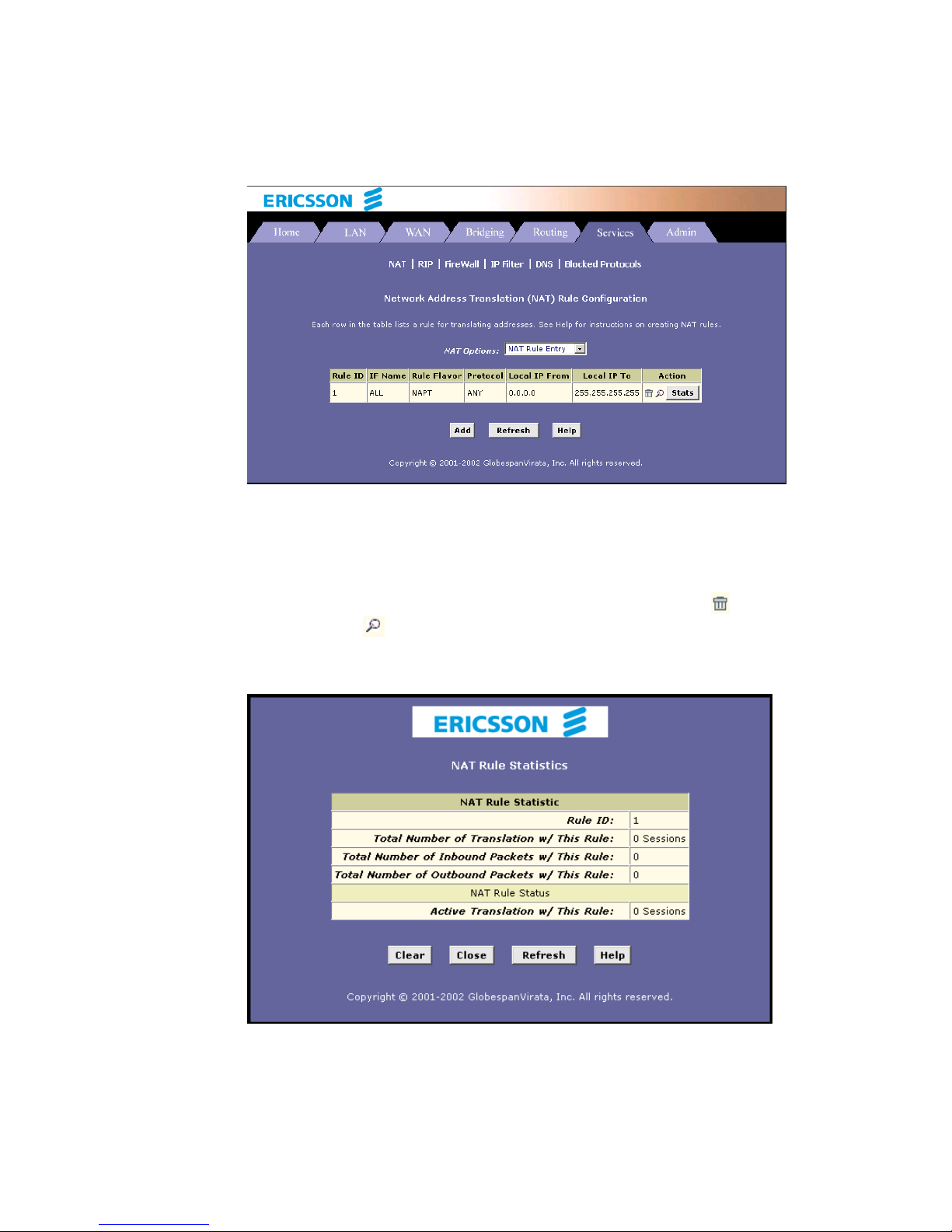
Configuring NAT
56 EN/LZT 108 6492 R2 - October 2003
The NAT Rule Configuration table displays a row containing basic
information for each rule. For a description of these fields, refer to the
instructions for adding rules in section 0 “Adding NAT Rules”.
From the NAT Rule Configuration page, you can click the Add button to
add a new rule, or use the icons in the “Action” column to delete (
) or
view details on (
) a rule. To view data on how often a specific NAT rule
has been used, click Stats in the “Action” column. A page similar to the one
below appears:
The statistics show how many times this rule has been invoked and how
many currently active sessions are using this rule. You can click the Clear
Page 65

Configuring NAT
EN/LZT 108 6492 R2 - October 2003
57
button to reset the statistics to zeros and the Refresh button to display
newly accumulated data.
8.4 Viewing Current NAT Translations
To view a list of NAT translations that have recently been performed and
which remain in effect (for any of the defined rules), select Services > NAT
and select NAT Translations in the NAT Options drop-down list The NAT
Translations page appears:
For each current NAT translation session, the table contains the following
fields:
Field Description
Trans Index The sequential number assigned to the IP session
used by this NAT translation session.
Rule ID The ID of the NAT rule invoked.
Interface The device interface on which the NAT rule was
invoked (from the rule definition).
Protocol The IP protocol used by the data packets that are
undergoing translations (from the rule definition).
Example: TCP, UDP, ICMP.
Alg Type The Application Level Gateway (ALG), if any, that
was used to enable this NAT translation. (ALGs are
special settings that certain applications require in
Page 66

Configuring NAT
58 EN/LZT 108 6492 R2 - October 2003
order to work while NAT is enabled).
NAT Direction The direction (incoming or outgoing) of the
translation (from the port definition). A NAT direction
is assigned to each port; the Ethernet port are
defined as incoming port, and the WAN ports are
defined as outgoing ports. The NAT direction is
determined by the interface on which the rule is
invoked.
Entry Age The elapsed time, in seconds, of the NAT translation
session.
You can click in the “Action” column to view additional details about a
NAT translation session. The NAT Translation – Details table is displayed.
In addition to the information displayed in the NAT Translations table, this
table displays the following for the selected current translation sessions:
Field Description
Translated InAddress:
The public IP address to which the private IP
address was translated.
In Address:
The private IP address that was translated.
Out Address:
The IP address of the outside destination (web, ftp,
site, etc.)
In/Out Pckets:
The number of incoming and outgoing IP packets
that have been translated in this translation session.
In Ports:
The actual port number corresponding to the LAN
computer.
Out Ports:
The port number associated with the destination
address.
Translated In Ports:
The port number to which the LAN computer’s
actual port number was translated.
Page 67

Configuring NAT
EN/LZT 108 6492 R2 - October 2003
59
8.5 Adding NAT Rules
This section explains how to create rules for the various NAT flavors.
8.5.1 The NAPT Rule
The NAT flavor NAPT was used in your default configuration. The NAPT
flavor translates all LAN-side private source IP addresses to a single public
IP address. It also translates the source port numbers to port numbers that
are defined on the NAT Global Configuration page.
To create a NAPT rule, proceed as follows:
1. Select Services > NAT > NAT Rule Entry > Add. The NAT Rule –
Add page appears:
2. In the ”Rule Flavor:” dropdown list, select NAPT.
3. In the “Rule ID:” field, enter an ID for the rule.
The Rule ID determines the order in which the rules are invoked
(the lowest numbered rule is invoked first, and so on). In some
case, two or more rules may be fined to act on the same set of IP
addresses. Once a data packet matches a rule, the data is acted
upon according to that rule and is not subjected to higher-numbered
rules.
4. From the “IF Name:” dropdown list, select the interface on the
HM210dp/di to which this rule applies.
Typically, NAT rules apply to communication between your LAN and
the Internet. Because the device uses the WAN interface (named
ppp-0 or eoa-0) to connect your LAN to your ISP, it is the usual IF
Name selection.
Page 68

Configuring NAT
60 EN/LZT 108 6492 R2 - October 2003
5. In the “Local Address From/To:” fields, type the starting and
ending IP addresses respectively, of the range of private IP
addresses you want to be translated. Or type the same address in
both fields to specify a single IP address.
If all LAN IP addresses should be translated, specify 0.0.0.0 and
255.255.255.255 respectively.
6. In the “Global Address:” field, type the address that you want to
serve as the publicly known IP address for the LAN computer.
7. When you have completed entering all information, click the Submit
button. A page appears to confirm the changes.
8. Click Close to return to the NAT Configuration page. The new rule
should no be displayed in the NAT Rule table.
9. On the NAT Configuration page, ensure that the Enable radio
button is selected and then click the Submit button. A page appears
to confirm your changes.
10. Select Admin > Commit & Reboot and click the Commit button to
save your changes to permanent storage.
8.5.2 The RDR Rule
You can create a RDR rule to make a computer on your LAN, such as Web
or FTP server, available to Internet users without requiring you to obtain a
public IP address for that computer. The computer’s private IP address is
translated to your public IP address for all incoming and outgoing data
packets.
NOTE! Without an RDR rule (or BIMAP rule), the HM210dp/di
blocks attempts by external computers to access your LAN
computers.
To create a RDR rule, proceed as follows:
1. Select Services > NAT > NAT Rule Entry > Add. The NAT Rule –
Add page appears:
Page 69
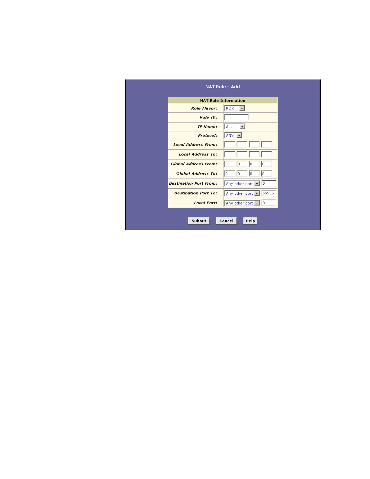
Configuring NAT
EN/LZT 108 6492 R2 - October 2003
61
2. In the ”Rule Flavor:” dropdown list, select RDR.
3. In the “Rule ID:” field, enter an ID for the rule.
The Rule ID determines the order in which the rules are invoked
(the lowest numbered rule is invoked first, and so on). In some
case, two or more rules may be fined to act on the same set of IP
addresses. Once a data packet matches a rule, the data is acted
upon according to that rule and is not subjected to higher-numbered
rules.
4. From the “IF Name:” dropdown list, select the interface on the
HM210dp/di to which this rule applies.
Typically, NAT rules apply to communication between your LAN and
the Internet. Because the device uses the WAN interface (named
ppp-0 or eoa-0) to connect your LAN to your ISP, it is the usual IF
Name selection.
5. Select a “Protocol:” to which this rule applies, or select ALL if the
rule applies to all data.
6. In the “Local Address From/To:” fields, type the same private IP
address, or the lowest and highest IP addresses in a range:
If you type the same IP address in both fields, incoming traffic that
matches the criteria of this rule will be redirected to that IP address.
If you type a range of IP addresses, incoming traffic will be
redirected to any available computer in that range. This option
Page 70

Configuring NAT
62 EN/LZT 108 6492 R2 - October 2003
would typically be used for load balancing, whereby traffic is
distributed among several redundant servers.
7. In the “Global Address From/To:” fields, type the public IP address
assigned to you by your ISP.
If you have multiple WAN interfaces, in both fields type the IP
address of the interface to which this rule applies. This rule will not
be enforced for data that arrives on WAN interfaces not specified
here.
If you have multiple WAN interfaces and want the rule to be
enforced on a range of them, type the starting and ending IP
addresses of the range.
8. Enter a destination port ID (or a range) as criteria for incoming
traffic.
Enter a starting and ending port number in the “Destination Port
From/To:” fields if incoming traffic destined for these port types
should be redirected to the address(es) specified in step 6. Or, enter
the same address in both fields.
9. If the publicly accessible LAN computer uses a non-standard port
number for the type of traffic it receives, type the non-standard port
number in the “Local Port:” field.
10. When you have completed entering all information, click the Submit
button. A page appears to confirm the changes.
11. Click Close to return to the NAT Configuration page. The new rule
should no be displayed in the NAT Rule table.
12. On the NAT Configuration page, ensure that the Enable radio
button is selected and then click the Submit button. A page appears
to confirm your changes.
13. Select Admin > Commit & Reboot and click the Commit button to
save your changes to permanent storage.
8.5.3 The BASIC Rule
The BASIC flavor translates the private (LAN-side) IP address to a public
(WAN-side) IP address, like the NAPT rule. However, unlike the NAPT rule,
the BASIC rule does not translate the port number in the packet header;
they are passed through untranslated. Therefore, the BASIC rule does not
provide the same level of security as the NAPT rule.
To create a RDR rule, proceed as follows:
Page 71
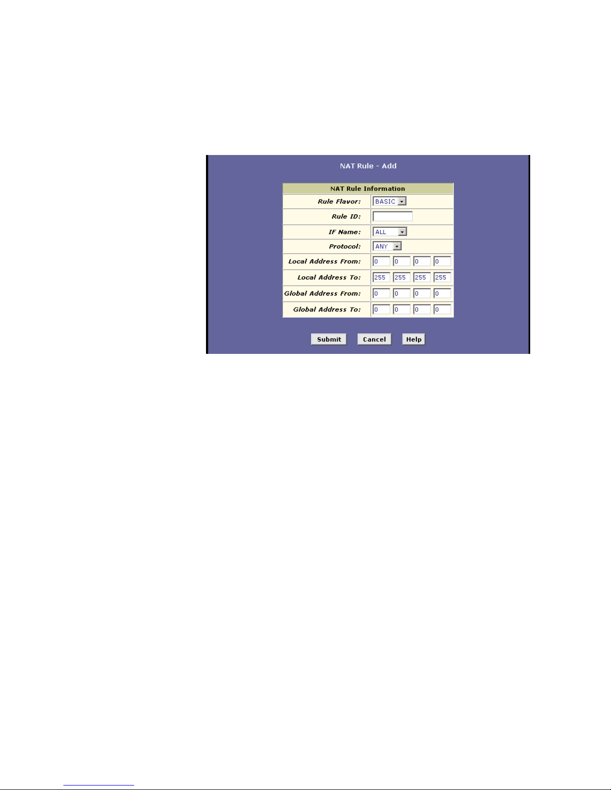
Configuring NAT
EN/LZT 108 6492 R2 - October 2003
63
1. Select Services > NAT > NAT Rule Entry > Add. The NAT Rule –
Add page appears:
2. In the ”Rule Flavor:” dropdown list, select BASIC.
3. In the “Rule ID:” field, enter an ID for the rule.
The Rule ID determines the order in which the rules are invoked
(the lowest numbered rule is invoked first, and so on). In some
case, two or more rules may be fined to act on the same set of IP
addresses. Once a data packet matches a rule, the data is acted
upon according to that rule and is not subjected to higher-numbered
rules.
4. From the “IF Name:” dropdown list, select the interface on the
HM210dp/di to which this rule applies.
Typically, NAT rules apply to communication between your LAN and
the Internet. Because the device uses the WAN interface (named
ppp-0 or eoa-0) to connect your LAN to your ISP, it is the usual IF
Name selection.
5. Select a “Protocol:” to which this rule applies, or select ALL if the
rule applies to all data.
6. In the “Local Address From/To:” fields, type the starting and
ending IP addresses that identify the range of private addresses you
want to be translated. Or, type the same IP address in both fields.
If you specify a range, each address will be translated in sequence
to a corresponding address in a range of global addresses (which
you specify in the next step).
Page 72

Configuring NAT
64 EN/LZT 108 6492 R2 - October 2003
7. In the “Global Address From/To:” fields, type the starting and
ending IP address that identify the pool of public IP addresses to be
translated to your private IP addresses. Or, type the same IP
address in both fields (if you also specified a single address in the
previous step).
8. When you have completed entering all information, click the Submit
button. A page appears to confirm the changes.
9. Click Close to return to the NAT Configuration page. The new rule
should no be displayed in the NAT Rule table.
10. On the NAT Configuration page, ensure that the Enable radio
button is selected and then click the Submit button. A page appears
to confirm your changes.
11. Select Admin > Commit & Reboot and click the Commit button to
save your changes to permanent storage.
8.5.4 The FILTER Rule
Like the BASIC flavor, the FILTER flavor translates public and private IP
addresses on a one-to-one basis. The FILTER flavor extends the capability
of the BASIC rule.
You can use the FILTER rule if you want an address translation to occur
only when your LAN computers initiate access to specific destinations. The
destinations can be identified by their IP addresses, ser type (such as FTP
or Web server), or both.
To create a FILTER rule, proceed as follows:
1. Select Services > NAT > NAT Rule Entry > Add. The NAT Rule –
Add page appears:
Page 73

Configuring NAT
EN/LZT 108 6492 R2 - October 2003
65
2. In the ”Rule Flavor:” dropdown list, select FILTER.
3. In the “Rule ID:” field, enter an ID for the rule.
The Rule ID determines the order in which the rules are invoked
(the lowest numbered rule is invoked first, and so on). In some
case, two or more rules may be fined to act on the same set of IP
addresses. Once a data packet matches a rule, the data is acted
upon according to that rule and is not subjected to higher-numbered
rules.
4. From the “IF Name:” dropdown list, select the interface on the
HM210dp/di to which this rule applies.
Typically, NAT rules apply to communication between your LAN and
the Internet. Because the device uses the WAN interface (named
ppp-0 or eoa-0) to connect your LAN to your ISP, it is the usual IF
Name selection.
5. Select a “Protocol:” to which this rule applies, or select ALL if the
rule applies to all data.
6. In the “Local Address From/To:” fields, type the starting and
ending IP addresses that identify the range of private addresses you
want to be translated. Or, type the same IP address in both fields.
If you specify a range, each address will be translated in sequence
Page 74

Configuring NAT
66 EN/LZT 108 6492 R2 - October 2003
to a corresponding address in a range of global addresses (which
you specify in the next step).
7. In the “Global Address From/To:” fields, type the starting and
ending IP address that identify the pool of public IP addresses to be
translated to your private IP addresses. Or, type the same IP
address in both fields (if you also specified a single address in the
previous step).
8. Enter a “Destination Address From/To:” ….
9. Enter a starting and ending port number in the “Destination Port
From/To:” fields if incoming traffic destined for these port types
should be redirected to the address(es) ….
10. When you have completed entering all information, click the Submit
button. A page appears to confirm the changes.
11. Click Close to return to the NAT Configuration page. The new rule
should no be displayed in the NAT Rule table.
12. On the NAT Configuration page, ensure that the Enable radio
button is selected and then click the Submit button. A page appears
to confirm your changes.
13. Select Admin > Commit & Reboot and click the Commit button to
save your changes to permanent storage.
8.5.5 The BIMAP Rule
Unlike the other NAT flavors, the BIMAP flavor performs address
translation in both the outgoing and incoming directions.
In the incoming direction, when the specified interface receives a packet
destined to your public IP address, this address is translated to the private
IP address of a computer on your LAN.
In the outgoing direction, the private source IP address in a data packet is
translated to the LAN’s public IP address.
BIMAP rules can be used to provide external access to a LAN device. They
do not provide the same level of security as RDR rules, because RDR rules
also reroute incoming packets based on the port ID. BIMAP rules do not
account for the port number, and therefore allow external access
regardless of the destination port type specified in the incoming packet.
To create a BIMAP rule, proceed as follows:
Page 75

Configuring NAT
EN/LZT 108 6492 R2 - October 2003
67
1. Select Services > NAT > NAT Rule Entry > Add. The NAT Rule –
Add page appears:
2. In the ”Rule Flavor:” dropdown list, select NAPT.
3. In the “Rule ID:” field, enter an ID for the rule.
The Rule ID determines the order in which the rules are invoked
(the lowest numbered rule is invoked first, and so on). In some
case, two or more rules may be fined to act on the same set of IP
addresses. Once a data packet matches a rule, the data is acted
upon according to that rule and is not subjected to higher-numbered
rules.
4. From the “IF Name:” dropdown list, select the interface on the
HM210dp/di to which this rule applies.
Typically, NAT rules apply to communication between your LAN and
the Internet. Because the device uses the WAN interface (named
ppp-0 or eoa-0) to connect your LAN to your ISP, it is the usual IF
Name selection.
5. In the “Local Address:” field, type the private IP address of the
computer to which you are granting external access.
6. In the “Global Address:” field, type the address that you want to
serve as the publicly known IP address for the LAN computer.
7. When you have completed entering all information, click the Submit
button. A page appears to confirm the changes.
8. Click Close to return to the NAT Configuration page. The new rule
should no be displayed in the NAT Rule table.
9. On the NAT Configuration page, ensure that the Enable radio
button is selected and then click the Submit button. A page appears
to confirm your changes.
Page 76

Configuring NAT
68 EN/LZT 108 6492 R2 - October 2003
10. Select Admin > Commit & Reboot and click the Commit button to
save your changes to permanent storage.
8.5.6 The PASS Rule
You can create a PASS rule to allow a range of IP addresses to remain
untranslated when another rule would otherwise do so.
The PASS rule must be assigned a rule ID that is a lower number than the
ID assigned to the rule it is intended to pass. If you want a specific IP
address or range of addresses to not be subject to an existing rule, say rule
ID #5, then you can create a PASS rule with ID #1 through #4.
To create a PASS rule, proceed as follows:
1. Select Services > NAT > NAT Rule Entry > Add. The NAT Rule –
Add page appears:
2. In the ”Rule Flavor:” dropdown list, select PASS.
3. In the “Rule ID:” field, enter an ID for the rule.
The Rule ID determines the order in which the rules are invoked
(the lowest numbered rule is invoked first, and so on). In some
case, two or more rules may be fined to act on the same set of IP
addresses. Once a data packet matches a rule, the data is acted
upon according to that rule and is not subjected to higher-numbered
rules.
4. From the “IF Name:” dropdown list, select the interface on the
HM210dp/di to which this rule applies.
Typically, NAT rules apply to communication between your LAN and
the Internet. Because the device uses the WAN interface (named
ppp-0 or eoa-0) to connect your LAN to your ISP, it is the usual IF
Name selection.
Page 77

Configuring NAT
EN/LZT 108 6492 R2 - October 2003
69
5. In the “Local Address From/To:” fields, type the lowest and highest
IP addresses that define the range of private addresses you want to
be passed without translation.
If you want the PASS rule to act on only one address, type that
address in both fields.
6. When you have completed entering all information, click the Submit
button. A page appears to confirm the changes.
7. Click Close to return to the NAT Configuration page. The new rule
should no be displayed in the NAT Rule table.
8. On the NAT Configuration page, ensure that the Enable radio
button is selected and then click the Submit button. A page appears
to confirm your changes.
9. Select Admin > Commit & Reboot and click the Commit button to
save your changes to permanent storage.
Page 78

Configuring DNS Server Addresses
70 EN/LZT 108 6492 R2 - October 2003
9 Configuring DNS Server Addresses
Domain Name System (DNS) servers map the user-friendly domain names
that users type into their Web browsers (e.g. “yahoo.com”) to the equivalent
numerical IP addresses that are used for Internet routing.
When a PC user types a domain name into a browser, the PC must first
send a request to a DNS server to obtain the equivalent IP address. The
DNS server will attempt to look up the domain name in its own database,
and will communicate with higher-level DNS servers when the name cannot
be found locally. When the address is found, it is sent back to the
requesting PC and is referenced in IP packets for the remainder of the
communication.
9.1 Assigning DNS Addresses
Multiple DNS addresses are useful to provide alternatives when one of the
servers is down or is encountering heavy traffic. ISPs typically provide
primary and secondary DNS addresses, and may provide additional
addresses. Your LAN PCs learn these DNS addresses in one of the
following ways:
Statically;
If your ISP provides you with their DNS server addresses, you can
assign them to each PC by modifying the PCs IP properties.
Dynamically from a DHCP pool;
You can configure the DHCP Server feature on the HM210dp/di
router and create an address pool that specifies the DNS addresses
to be distributed to the PCs. Refer to section 7.3 “Configuring DHCP
Server” for instructions on creating DHCP address pools.
In either case, you can specify the actual addresses of the ISP’s DNS
servers (on the PC or in the DHCP pool), or you can specify the
address of the LAN port on the HM210dp/di (e.g. 192.168.1.1). When
you specify the LAN port IP address, the device performs DNS Relay,
as described in the following section.
Follow the procedures below to connect related devices.
NOTE! If you specify the actual DNS addresses on the PCs or in the
DHCP pool, the DNS Relay feature is not used.
Page 79

Configuring DNS Server Addresses
EN/LZT 108 6492 R2 - October 2003
71
9.2 Overview of DNS Relay
When you specify the HM210dp/di’s LAN port IP address as the DNS
address, then the device automatically performs “DNS relay”; i.e. because
the device itself is not a DNS server, it forwards domain name lookup
requests it receives from the LAN PCs to a DNS server at the ISP. It then
relays the DNS server’s response to the PC.
When performing DNS relay, the HM210dp/di must maintain the IP
addresses of the DNS servers it contacts. It can learn these addresses in
either or both of the following ways:
Learned through PPP;
If the device uses a PPP connection to the ISP, the primary and
secondary DNS addresses can be learned via the PPP protocol. To
use this method, the “Use DNS” checkbox must be selected in the
PPP interface properties.
Using this option provides the advantage that you will not need to
reconfigure the PCs or the HM210dp/di if the ISP changes their
DNS addresses.
Configured on the HM210dp/di;
You can use the device’s DNS feature to specify the ISP’s DNS
addresses. If the device also uses a PPP interface with the “Use
DNS” property enabled, then these configured addresses will be
used in addition to the two addresses learned through PPP. If “Use
DNS” is not enabled, or if a protocol other than PPP is used (such
as EoA), then these configured addresses will be used as the
primary and secondary DNS addresses.
9.3 Configuring DNS Relay
Follow these steps to configure DNS Relay:
1. Configure the LAN PCs as DHCP clients of the HM210dp/di.
2. Go to LAN > DHCP Server, enter the LAN IP address (e.g.
192.168.1.1) or 0.0.0.0 as the DNS address in the DHCP server
pool.
By default, 0.0.0.0 is already set as the DNS of the DHCP pool.
3. Determine how the HM210dp/di will learn the DNS server address:
Option 1 – Using a PPP connection to learn the DNS
Use DNS must be enabled in the PPP interface properties. Go to
Routing > PPP and check the PPP interface details:
Page 80
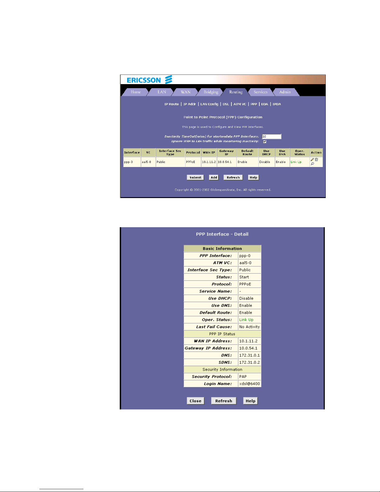
Configuring DNS Server Addresses
72 EN/LZT 108 6492 R2 - October 2003
If “Use DNS” is disabled, you must delete the interface and create a
new one with the new setting.
Option 2 – Configuring DNS on the HM210dp/di:
Page 81

Configuring DNS Server Addresses
EN/LZT 108 6492 R2 - October 2003
73
You can configure the DNS server address to be relayed on the
modem if one of the following circumstances applies:
Not using PPP connection to the ISP (or a protocol other
than PPP is used, such as EoA).
You use PPP connection and “Use DNS” is already
Enabled. Then these configured addresses will be used in
addition to those DNS addresses learned through PPP.
You use PPP connection and “Use DNS” is Disabled. Then
these configured addresses will be used.
Go to Service > DNS to display the DNS Configuration page:
Type the IP address of the DNS server in an empty row and click
Add. Click the “Enable” radio button, and then click the Sumbit
button.
Select Admin > Commit & Reboot and click the Commit button
to save your changes to permanent storage.
Page 82

Configuring RIP
74 EN/LZT 108 6492 R2 - October 2003
10 Configuring RIP
The HM210dp/di can be configured to communicate with other routing
devices to determine the best path for sending data to its intended
destination. This chapter describes how to configure your HM210dp/di to
use one of these, called the Routing Information Protocol (RIP).
10.1 Overview of RIP
RIP is an Internet protocol you can set up to share routing table information
with other routing devices on your LAN, at your ISP’s location, or on remote
networks connected to your network via the ADSL line. Generally, RIP is
used to enable communication on autonomous networks. An autonomous
network is one in which all of the computers are administered by the same
entity. An autonomous network may be a single network, or a grouping of
several networks under the same administration. An example of an
autonomous network is a corporate LAN, including devices that can access
it from remote locations, such as the computers telecommuters use.
Using RIP, each device sends its routing table to its closes neighbor every
30 seconds. The neighboring device in turn passes the information on to its
next neighbor and so on until all devices in the autonomous network have
the same set of routes.
Most small home or office networks do not need to use RIP; they have only
one router, such as the HM210dp/di, and one path to an ISP. In these
cases there is no need to share routes, because all Internet data from the
network is sent to the same ISP gateway.
You may want to configure RIP if any of the following circumstances apply
to your network:
Your network includes an additional router or RIP-enabled PC. The
HM210dp/di and the router will need to communicate via RIP to
share their routing tables.
Your network connects via the ADSL line to a remote network, such
as a corporate network. In order for your LAN to learn the routes
used within your corporate network, they should both
be configured
with RIP.
Your ISP requests that you run RIP for communication with devices
on their network.
Page 83
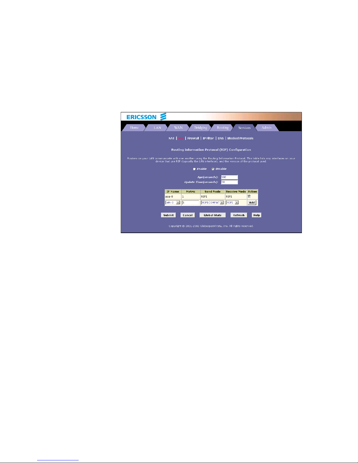
Configuring RIP
EN/LZT 108 6492 R2 - October 2003
75
10.2 Configuring the RIP
Follow the steps below to configure your HM210dp/di to use RIP:
1. Select Services > RIP and the RIP Configuration page appears:
2. The page contains radio buttons for enabling or disabling the RIP
feature and a table listing interfaces on which the protocol is
currently running. The first time you open this page, the table may
be empty.
3. If necessary, change the “Age(seconds)” and “Update
Time(seconds):” values. These are global settings for all interfaces
that use RIP.
Age time is the amount of time in seconds that the device’s RIP
table will retain each route that it learns from adjacent computers.
Update Time specifies how frequently the HM210dp/di will send out
its routing table to its neighbors.
4. In the “IF Name” column, select the interface on which you want to
enable RIP.
For communication with RIP-enables devices on your LAN, select
eth-0 or the name of the appropriate virtual Ethernet interface.
For communication with your ISP or a remote LAN, select the
corresponding ppp, eoa, or other WAN interface.
5. Select a “Metric” value (hop count) for the interface.
RIP uses a “hop count” as a way to determine the best path to a
Page 84

Configuring RIP
76 EN/LZT 108 6492 R2 - October 2003
given destination in the network. The hop count is the sum of the
metric values assigned to each port through which data is passed
before reaching the destination. Among several alternative routes,
the one with the lowest hop count is considered the fastest path.
For example, if you assign this port a metric of 1, then RIP will add 1
to the hop count when calculating a route that passes through this
port. If you know that communication via this interface is slower than
through other interfaces on your network, you can assign it a higher
metric value that the others.
You can select any integer from 1 to 15.
6. Select a “Send Mode” and a “Receive Mode” according to the
following:
The Send Mode setting indicates the RIP version this interface will
use when it sends its route information to other devices.
The Receive Mode setting indicates the RIP version(s) in which
information must be passed to the HM210dp/di in order to be
accepted into its routing table.
RIP version 1 is the original RIP protocol. Select RIP1 if you have
devices that communicate with this interface that understand RIP
version 1 only.
RIP version 2 is the preferred selection because it supports
(classless” IP addresses (which are used to create subnets) and
other features. Select RIP2 if all other routing devices on the
autonomous network support this version of the protocol.
7. Click Add in the “Action” column and the new RIP entry will be
displayed in the table.
8. Click the “Enable” radio button to enable the RIP feature.
9. When you are finished defining RIP interfaces, click the Submit
button. A page appears to confirm your changes.
10. Select Admin > Commit & Reboot and click the Commit button to
save your changes to permanent storage.
10.3 Viewing RIP Statistics
From the RIP Configuration page, you can click the Global Stats button to
view statistics on attempts to send and receive route table data over RIP
enabled interfaces on the HM210dp/di:
Page 85
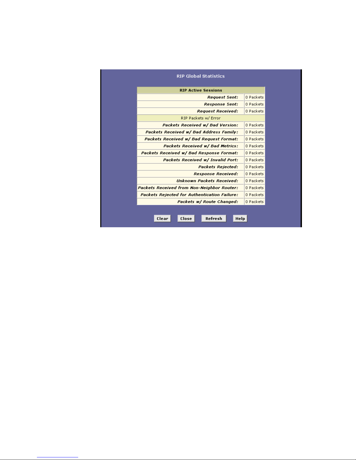
Configuring RIP
EN/LZT 108 6492 R2 - October 2003
77
You can click the Clear button to reset all statistics to zero and the Refresh
button to display any newly accumulated data.
Page 86
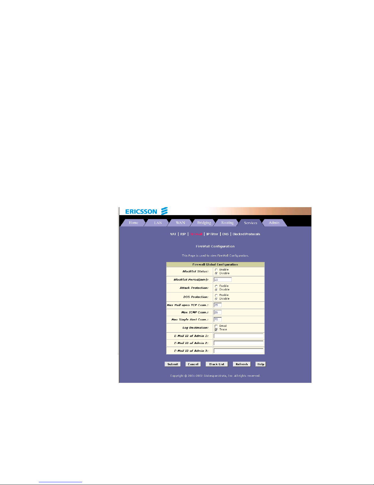
Configuring Firewall Settings
78 EN/LZT 108 6492 R2 - October 2003
11 Configuring Firewall Settings
The Configuration Manager provides built-in firewall functions, enabling you
to protect the system against denial of service (DoS) attacks and other
types of malicious accesses to your LAN. You can also specify how to
monitor attempted attacks, and who should be automatically notified.
11.1 Global Firewall Settings
Follow the steps below to configure the global firewall settings:
1. Select Services > Firewall and the Firewall Configuration page
appears:
2. Configure the settings according to the following:
Page 87

Configuring Firewall Settings
EN/LZT 108 6492 R2 - October 2003
79
Field Description
Blacklist Status:
If you want the device to maintain and use a
black list, click Enable. Click Disable if you do
not want to maintain a list.
Blacklist Period(min):
Specifies the number of minutes that a
computer’s IP address will remain on the black
list.
Attack Protection:
Select Enable to use the build-in firewall
protections that prevent the following common
types of attacks:
IP Spoofing – Sending packets over the WAN
interface using an internal LAN IP address as the
source address.
Tear Drop – Sending packets that contain overlapping fragments.
Smurf and Fraggle – Sending packets that use
the WAN or LAN IP broadcast address as the
source address.
Land Attack – Sending packets that use the
same address as the source and destination
address.
Ping of Death – Illegal IP packets length.
DOS Protection:
Click the Enable radio button to use the following
denial of service protections:
SYN DoS, ICMP DoS and Per-host DoS
protection.
Max Half open TCP
Conn.:
Sets the percentage of concurrent IP sessions
that can be in the half-open state. In ordinary
TCP communication, packets are in the half-open
state only briefly as a connection is being
initiated; the state changes to active when
packets are being exchanged, or closed when
the exchange is complete. TCP connections in
the half-open state can use up the available IP
sessions.
If the percentage is exceeded, then the half-open
sessions will be closed and replaced with new
sessions as they are initiated.
Max ICMP Conn.:
Sets the percentage of concurrent IP sessions
that can be used for ICMP messages.
If the percentage is exceeded, older ICMP IP
sessions will be replaced by new sessions as
Page 88

Configuring Firewall Settings
80 EN/LZT 108 6492 R2 - October 2003
they are initiated.
Max Single Host
Conn.:
Sets the percentage of concurrent IP sessions
that can originate from a single computer. This
percentage should take into account the number
of hosts on the LAN.
Log Destination:
Specifies how attempted violations of the firewall
settings will be tracked. Records of such events
can be sent out via Ethernet to be handled by a
system utility Ethernet to (Trace) or can be emailed to specified administrators.
E-Mail ID of Admin
1/2/3:
Specifies the e-mail address(es) of the
administrator(s) who should receive notices of
any attempted firewall violations. Type the
address(es) in standard internet e-mail address
format, e.g.
j.smith@onecompany.xom
The e-mail message will contain the time of the
violation, the source address of the computer
responsible for the violation, the destination IP
address, the protocol being used, the source and
destination ports, and the number of violations
occurring the previous 30 minutes. If the ICMP
protocol were being used, then instead of the
source and destination ports, the e-mail will
report the ICMP code and type.
3. Click the Submit button.
4. Select Admin > Commit & Reboot and click the Commit button to
save your changes to permanent storage.
11.2 Configuring IP Filters
When you define an IP filter rule and enable the feature, you instruct the
HM210dp/di to examine each data packet it receives to determine whether
it meets criteria set forth in the rule. The criteria can include the size of the
packet, the network or internet protocol it is carrying, the direction in which
it is traveling (for example from the LAN to the Internet or vice versa), the IP
address of the sending computer, the destination IP address, and other
characteristics of the packet data.
If the packet matches the criteria established in a rule, the packet can either
be accepted (forwarded towards its destination) or denied (discarded)
depending on the action specified in the rule.
Page 89
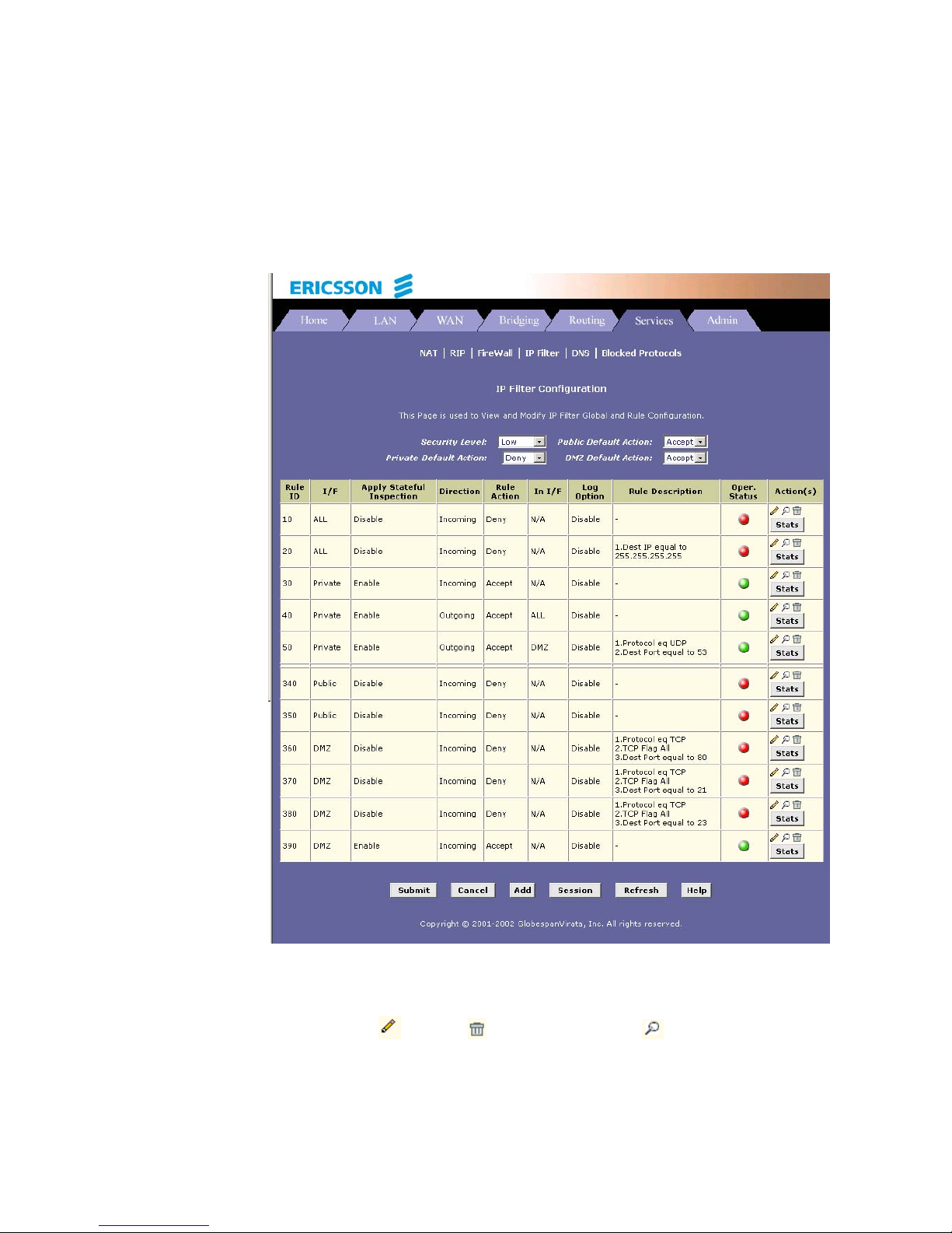
Configuring Firewall Settings
EN/LZT 108 6492 R2 - October 2003
81
11.2.1 Viewing Your IP Filter Configuration
To view your IP filter configuration, select Services > IP Filter. The IP
Filter Configuration page appears:
The IP Filter Configuration page displays global settings that you can
modify, and the IP filter rule table, which shows all currently established
rules. When rules are defined, you can use the icons in the “Action(s)”
column to edit (
), delete ( ) and view details on ( ) the corresponding
rule.
Page 90

Configuring Firewall Settings
82 EN/LZT 108 6492 R2 - October 2003
11.2.2 Configuring IP Filter Global Settings
The IP Filter Configuration page enables you to configure several global
IP Filter settings, and displays a table showing all existing IP Filter rules.
The global settings that you can configure are:
Security Level: When High is selected, only those rules that are
assigned a security value of “High” will be in effect. The same is true
for the Medium and Low settings. When None is selected, IP
Filtering is disabled.
Private/Public/DMZ Default Action: This setting specifies a default
action to be taken (Accept or Deny on private, public or DMZ-type
devise interfaces when they receive packets that do not match any
of the filtering rules.
Private – Typically, the global setting for private interfaces is
Accept, so that LAN computers have access to the Internet
connection of the HM210dp/di.
Public – The interface connect to the Internet, e.g. PPP, EoA and
IpoA interfaces. Typically, the global setting for public interfaces is
Deny, so that all accesses to your LAN initiated from external
computers are denied (discarded at the public interface), except for
those allowed by a specific IP Filter rule.
DMZ – Refers to computers that are available for both public and innetwork accesses (such as a company’s public Web server).
Packets received on a DMZ interface – whether from a LAN or
external source – are subject to a set of protections that is in
between public and private interfaces. The global setting for DMZtype interfaces may be set to Deny so that all attempts to access
these servers are denied by default. The administrator may then
configure IP Filter rules to allow accesses of certain types.
11.2.3 Creating IP Filter Rules
To create an IP filter rule, you set various criteria that must be met in order
for the rule to be invoked. Use these instructions to add a new IP filter rule,
and refer to the examples in section 11.2.3.1 for assistance:
1. On the main IP Filter Configuration page, click the Add button.
The IP Filter Rule – Add page appears:
Page 91

Configuring Firewall Settings
EN/LZT 108 6492 R2 - October 2003
83
2. Enter or select data for each field that applies to your rule:
Page 92

Configuring Firewall Settings
84 EN/LZT 108 6492 R2 - October 2003
Field Description
Rule ID:
Rules are processed from lowest to highest on
each data packet, until a match is found. It is
recommended that you assign rule Ids in
multiples of 5 or 10 (e.g. 10, 20, 30) so that you
leave enough space between them for inserting a
new rule if necessary.
Action:
The action can be Accept (forward to
destination) or Deny (discard the packet).
Direction:
Incoming refers to packets coming from the
LAN, and outgoing refers to packets going to the
Internet.
You can use rules that specify the incoming
direction to restrict external computers from
accessing your LAN.
Interface:
The interface on which the rule will take affect.
In Interface:
The interface from which packets must have
been forwarded to the interface specified in the
previous section. This option is valid only for the
outgoing direction.
Log Option:
When Enable is selected, a log entry will be
created on the system each time this rule is
invoked.
Security Level:
The security level that must be enabled globally
for this rule to take affect. A rule will be active
only if its security level is the same as the
globally configured setting (shown on the main IP
Filter page). For example, if the rule is set to
“Medium” and the global firewall level is set to
“Medium”, then the rule w ill be active; but if the
global firewall level is set to “High” or “Low”, then
the rule will be inactive.
Blacklist Status:
Specifies whether or not a violation of this rule w
ill result in the offending computer’s IP address
being added to the Black List, which blocks the
router from forwarding packets from that source
for a specified period of time.
Log Tag:
A description of up to 16 characters to be
recorded in the log in the event that a packet
violates this rule. Be sure to set the Log Option to
Page 93

Configuring Firewall Settings
EN/LZT 108 6492 R2 - October 2003
85
Enable if you configure a Log Tag.
Start/End Time:
The time range during which this rule is to be in
effect, specified in military units.
Src IP Address:
IP address criteria for the source computer(s)
from which the packet originates. Use the
following expressions to specify IP:
any: any source IP address
lt: less than
lteq: less than or equal to
gt: greater than
eq: equal to
neq: not equal to
range: within the specified range, inclusive
out of range: outside the specified range
self: the IP address of the router interface on
which this rule takes effect.
Dest IP Address:
IP address rule criteria for the destination
computer(s), i.e. the IP address of the computer
to which the packet is being sent.
In addition to the options described for the “Src
IP Address” field, the following option is
available:
bcast: Specifies that the rule will be invoked for
any packets sent to the broadcast address for the
receiving interface. (The broadcast address is
used to send packets to all hosts on the LAN or
subnet connected to the specified interface).
When you select this option, you do not need to
specify the address, so the address fields are
dimmed.
Protocol:
The basic IP protocol criteria that must be met for
a rule to be invoked. Using the options in the
drop-down list, you can specify that packets must
contain the selected protocol (eq), that they must
not contain the specified protocol (neq), or that
the rule can be invoked regardless of the protocol
(any). TCP, UDP and ICMP are commonly IP
protocols; others can be identified by number
from 0-255 as defined by IANA.
Apply Stateful
Inspection:
If this option is enabled, then stateful filtering is
performed and the rule is also applied in the
other direction on the given interface during an IP
session.
Page 94

Configuring Firewall Settings
86 EN/LZT 108 6492 R2 - October 2003
Source Port:
Port number criteria for the computer(s) from
which the packet originates. This field will be
dimmed (unavailable for entry) if you have not
specified a protocol critera. See the description of
Src IP Address for the selection options.
Dest Port:
Port number criteria for the destination
computer(s), i.e. the port number of the type of
computer to which the packet is being sent. This
field will be dimmed (unavailable for entry) unless
you have selected TCP or UDP as the protocol.
See the description of Src IP Address for the
selection options.
TCP Flag:
Specifies whether the rule should apply only to
TCP packets that contain the synchronous (SYN)
flag, only to those that contain the nonsynchronous (NOT-SYN) flag, or to all TCP
packets. This field will be dimmed (unavailable
for entry) unless you selected TCP as the
protocol.
ICMP Type:
Specifies whether the value in the type field in
ICMP packet headers will be used as a criteria.
The code value can be any decimal value from 0
to 255. You can specify that the value must be
equal (eq) or not equal (neq) to the specified
value, or you can select any to enable the rule to
be invoked on all ICMP packets. This field will be
dimmed (unavailable for entry) unless you
specify ICMP as the protocol.
ICMP Code:
Specifies whether the value in the code field in
ICMP packet headers will be used as criteria.
The code value can be any decimal value from 0
to 255. You can specify that the value must be
equal (eq) or not equal (neq) to the specified
value, or you can select any to enable the rule to
be invoked on all ICMP packets. This field will be
dimmed (unavailable for entry) unless you
specify ICMP as the protocol.
IP Frag Pkt:
Determines how the rule applies to IP packets
that contain fragments. You can choose from the
following options:
Yes: The rule will be applied only to packets that
contain fragments.
No: The rule will be applied only to packets that
do not contain fragments.
Page 95

Configuring Firewall Settings
EN/LZT 108 6492 R2 - October 2003
87
Ignore: (Default) The rule will be applied to
packets whether or not they contain fragments,
assuming that they match the other criteria.
IP Option Pkt:
Determines whether the rule should apply to IP
packets that have options specified in their
packet headers. You can choose from the
following options:
Yes: The rule will be applied only to packets that
contain header options.
No: The rule will be applied only to packets that
do not contain header options.
Ignore: (Default) The rule will be applied to
packets whether or not they contain header
options, assuming that they match the other
criteria.
Packet Size:
Specifies that the IP Filter rule will take affect
only on packets whose size in bytes matches this
criteria. (lt=less than, gt=greater than, lteq=less
than or equal to, etc).
TOD Rule Status:
The Time of Day Rule Status determines how the
Start Time/End Time settings are used.
Enable: (Default) The rule is in effect for the
specified time period.
Disable: The rule is not in effect for the specified
time period, but is effective at all other times.
3. When you are done selecting criteria, ensure that the Enable radio
button is selected and then click the Submit button.
If the security level of the rule matches the globally configured
setting, a green ball in the “Status” column for that rule, indicating
that the rule is now in effect. A red ball will display when the rule is
disabled or if its security level is different than the globally
configured level.
4. Ensure that the Security Level and Private/Public/DMZ Default
Action settings on the IP Filter configuration page are configured
as needed, then click the Submit button.
5. Select Admin > Commit & Reboot and click the Commit button to
save your changes to permanent storage.
Page 96

Configuring Firewall Settings
88 EN/LZT 108 6492 R2 - October 2003
11.2.3.1 IP Filter Rule Examples
Example 1 – Blocking a specific computer on your LAN from accessing
web servers on the Internet;
1. Add a new rule for outgoing packets on the ppp-0 interface from any
incoming interface (this would include the eth-0 interface, for
example).
2. Specify a source IP address of the computer you want to block.
3. Specify the Protocol = TCP and enable the Store State setting.
4. Specify a destination port = 80, which is the standard port number
for web servers.
5. Enable the rule by clicking the radio button at the top of the page.
6. Click Submit to create the rule.
7. On the IP Filter Configuration page, set the Security Level to the
same level you chose for the rule, and set both the Private Default
Action and the Public Default Action to Accept.
8. Click Submit to commit your changes.
Example 2 – Blocking Telnet access to the device;
1. Add a new rule for incoming packets on the ppp-0 interface.
2. Specify that the packet must contain the TCP protocol, and must be
destined for port 23, the standard port number used for the Telnet
protocol.
3. Enable the rule by clicking the radio button at the top of the page.
4. Click Submit to create the rule, and commit your changes.
11.2.4 Viewing IP Filter Statistics
To view statistics on how many packets were accepted or denied for a rule,
select Services > IP Filter > Stats in the row corresponding to the rule.
The IP Filter Rule – Statistics page displays:
Page 97
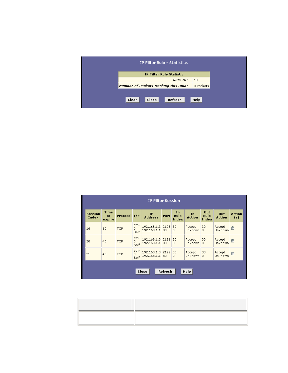
Configuring Firewall Settings
EN/LZT 108 6492 R2 - October 2003
89
You can click the Clear button to reset the count to zero and the Refresh
button to display newly accumulated data.
11.2.5 Managing Current IP Filter Sessions
When two computers communicate using the IP protocol, an IP session is
created for the duration of the communication. The HM210dp/di allows a
fixed number of concurrent IP sessions. You can view information about
each current IP session and delete sessions (for security reasons, for
example).
To view all current IP sessions, select Services > IP Filter > Session to
display the IP Filters Session page:
The IP Filter Session table displays the following fields for each current IP
session:
Field Description
Session Index The ID assigned by the system to the IP session (all
sessions, whether or not they are affected by an IP
Page 98

Configuring Firewall Settings
90 EN/LZT 108 6492 R2 - October 2003
filter rule, are assigned a session index).
Time to expire The number of seconds in which the connection will
automatically expire.
Protocol The underlying IP protocol used on the connection,
such as TCP, UDP, IGMP, etc.
I/F The interface on which the IP Filter rule is effective.
IP Address The IP address involved in the communication. The
first one shown is the initiator of the communication.
Port The hardware addresses of the ports involved in the
communication.
In/Out Rule Index The number of the IP Filter rule that is applied to this
session (assigned when the rule was created).
In/Out Action The action (accept, deny, or unknown) being taken on
data coming in to or going out from the interface. This
action is specified in the rule definition.
Actions
Provides a icon you can click on (
) to delete the IP
session. When you delete a session, the
communication between is discontinued.
You can click the Refresh button to display newly accumulated data.
11.3 Blocking Specific Protocols
The Blocked Protocols feature enables you to prevent the HM210dp/di from
passing any data that uses a particular protocol. Unlike the IP Filter feature,
you cannot specify additional criteria for blocked protocols, such as
particular users or destinations.
NOTE! Blocking certain protocols may disrupt or disable your
network communication or Internet access. DO NOT use this
feature unless you are certain that a particular protocol is not
needed or wanted on your network.
To block specific protocols running across the system, select Services >
Blocked Protocols. The Blocked Protocols page appears:
Page 99
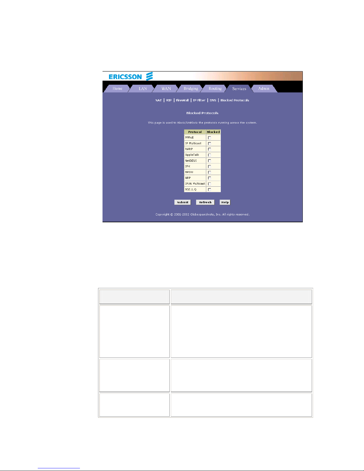
Configuring Firewall Settings
EN/LZT 108 6492 R2 - October 2003
91
Check the protocol type you want to block and click the Submit button.
Make sure to use the Commit feature to save your changes to the
permanent memory.
To unblock a specific protocol, uncheck the protocol and repeat the submit
and commit tasks.
The following list describes each of the available protocols:
Protocol Description
PPPoE Point-to-Point Protocol over Ethernet. Many DSL
modems use PPPoE to establish and maintain a
connection with a service provider. PPPoE provides a
means of logging in to the ISPs servers so that they
can authenticate you as a customer and provide you
access to the Internet. Check with your ISP before
blocking this protocol.
IP Multicast IP Multicast is an extension to the IP protocol. It
enables individual packets to be sent to multiple hosts
on the Internet, and is often used for handling e-mail
mailing lists and teleconferencing/videoconferencing.
RARP Reverse Address Resolution Protocol. This IP
protocol provides a way for computers to determine
their own IP addresses when they only know their
Page 100

Configuring Firewall Settings
92 EN/LZT 108 6492 R2 - October 2003
hardware address (i.e. MAC addresses). Certain
types of computers, such as diskless workstations,
must use RARP to determine their IP address before
communicating with other network devices.
AppleTalk A networking protocol used for Apple Macintosh
networks.
NetBEUI NetBIOS Enhanced User Interface. On many LAN
operating systems, the NetBEUI rotocol provides the
method by which computers identify themselves to
and communicate with each other.
IPX Internetwork Packet Exchange. A networking protocol
used on Novell Netware-based LANs.
BPDU Bridge Protocol Data Unit. BPDUs are data messages
that are exchanged across the switches between
LANs that are connected by a bridge. BPDU packets
contain information on ports, addresses, priorities,
and costs, and are exchanged across bridges to
detect and eliminate loops in a network.
ARP Address Resolution Protocol. Computers on a LAN
use ARP to learn the hardware addresses (i.e. MAC
addresses) of other computers when they know only
their IP addresses.
IPV6 Multicast IP Multicasting under IP Protocol version 6. See IP
Multicast above.
802.1.Q This IEEE specification defines a protocol for virtual
LANs on Ethernet networks. A virtual LAN is a group
of PCs that function as a local area network, even
though the PCs may not be physically connected.
They are commonly used to facilitate administration of
large networks.
 Loading...