

Page 1

4/00021-2/FEA 209 544/6 C Troubleshooting guide
Troubleshooting guide.
GF 788/768/788e Standard.
Contents page
Component Classes 2
Abbreviations 3
Pin placements 4
1. RTC 6
2. Keyboard 8
3. Display 13
4. Charging 18
5. Illumination and buzzer 23
6. Doesn’t start 28
7. SIM fault 37
8. No serv 41
9. Audio 45
10. Spare part list 53
1
Page 2

Troubleshooting guide 4/00021-2/FEA 209 544/6 C
Component classes.
All the components in the phone are divided into classes and after every component in the troubleshooting guide
you have a class written. The components are dividedintofourclasses:A,B,CandD.Theclassofthecomponent
depends on how much of the phone’s performance is affected when replacing it.
Class A and B: A test call towards the “real” net (not only towards a GSM test instrument) and run it through
the normal tests is enough to verify the functionality since the performance of the phone is only
slightly affected.
Class C: Since the tolerances of the component are so great it can substantially affect the performance of
the phone you need to calibrate it at station level after replacing the component.
Class D: Class D components need to be calibrated at board level using very advanced equipment and
may therefore not be replaced.
2
Page 3

4/00021-2/FEA 209 544/6 C Troubleshooting guide
Abbreviations.
A: The power module at some phones.
B: Crystal.
C: Capacitor.
D: Digital circuit.
F: Over voltage protection.
G: VCO.
H: Buzzer, LED, pads for display.
J: Connector.
L: Coil.
N: Analogue circuit.
R: Resistor.
S: Keyboard pads.
U: BALUN. A circuit that converts a signal from balanced to unbalanced or the opposite.
V: Transistor or diode.
X: Contact surface at the circuit board.
Z: Filter.
AGND: Ground for analogue signals.
DCIO: DC voltage used for charging the battery through the system connector.
DCON: Logical signal from the processor that keeps the phone running after you’ve released the On/Off
key.
EXTAUD: Input signal at the system connector that the processor uses to determine if there’s any external
audio equipment attached.
EXTAUDI: The same signal as the EXTAUD signal but at the processor side.
GND: Ground.
LED3K: Logical signal used to activate the background illumination.
ONSRQ: Voltage from the On/Off key that starts the phone.
PORTHF: Input signal at the system connector that the processor uses to determine if there’s any handsfree
equipment attached.
PHF1: The same signal as PORTHF but at the processor side.
REGON: Logical signal that activates the voltage regulators.
RTC: Real time clock. The clock that keeps track of time and date.
SIMCLK: Clock signal from the processor used for communications with the SIM.
SIMDAT: Data signal from the processor used for communications with the SIM.
SIMRST: Reset signal from the processor used for communications with the SIM.
SIMVCC: Feed voltage for the SIM.
SWDC: Switched VBATT.
VANA: DC voltage for the analogue part of the logic (N800).
VBATT: Battery voltage.
VDIG: DC voltage for the processor and memory.
VDSP: DC voltage for the DSP (Digital Signal Processor).
VLCD: DC voltage for the display that controls the contrast.
VRAD: DC voltage for the radio part except the synthesizer.
VRPAD: DC voltage for the radio part in D600 (also used for the top diode and the buzzer).
VRTC: DC voltage for the real time clock.
VSIMPAD: VDIG voltage that has been switched up to 5V used for SIM.
VVCO: DC voltage for the synthesizer.
I2C: Two line serial communications standard using one clock and one data line.
LO: Local oscillator.
PWM: Pulse width modulation.
3
Page 4
Troubleshooting guide 4/00021-2/FEA 209 544/6 C
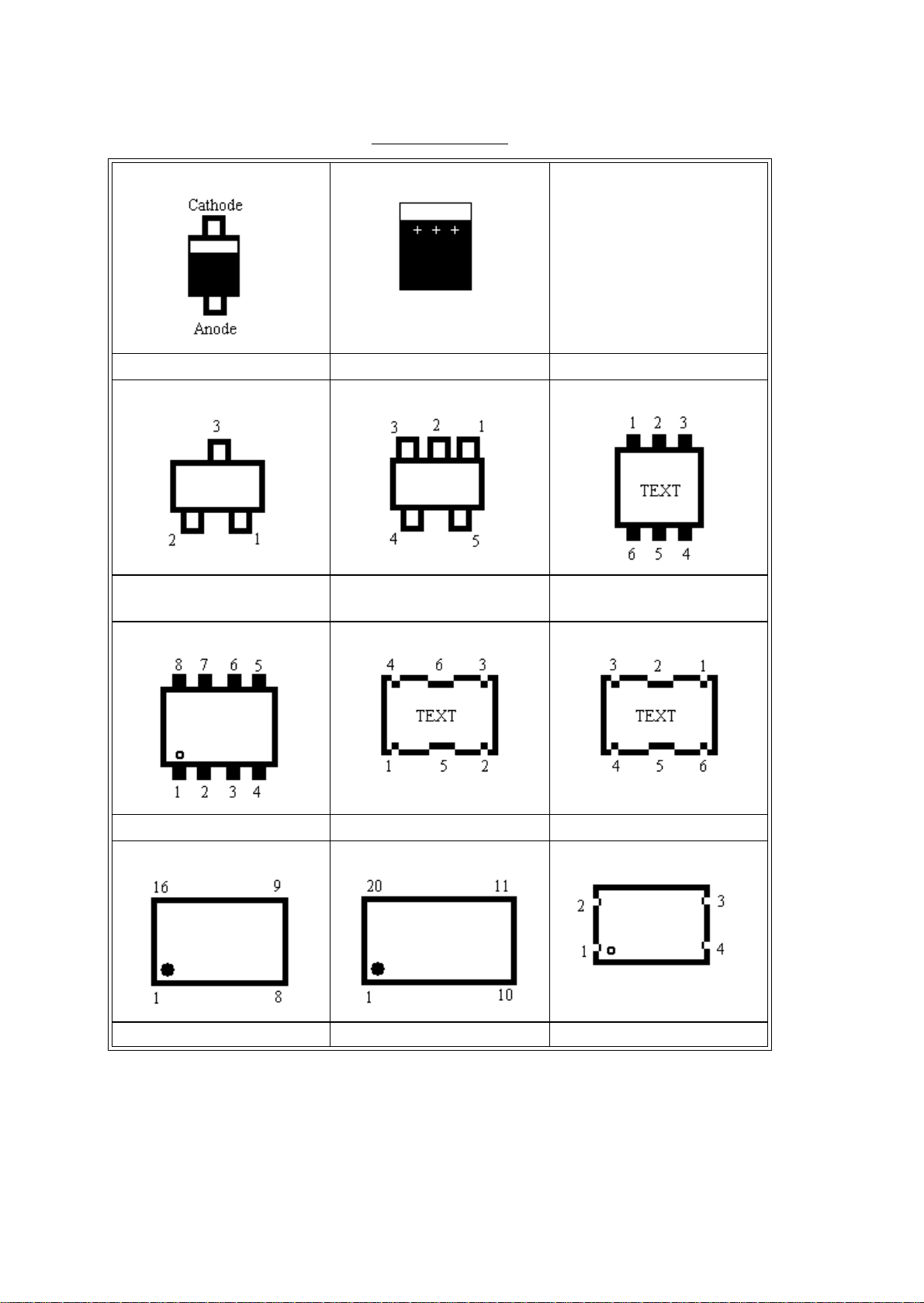
Pin placements
Single diode (PIN diode). Electrolytic capacitor.
Double diode or single trans-
stor.
Eight pin circuit. 688 VCO circuit 788 VCO circuit
Sixteen pin circuit Twenty pin circuit Crystal
Five pin circuit (usually volt-
age regulator).
Double transistor.
4
Page 5

4/00021-2/FEA 209 544/6 C Troubleshooting guide
N800 D900
D600
D620 D610
5
Page 6

Troubleshooting guide 4/00021-2/FEA 209 544/6 C
1. RTC
1.1 Find the fault.
Start the phone with a SIM-card and a fully charged battery inserted. Set the correct time. Remove the battery and
reinsert it after a minute.
• If the clock says 00:00, go to 1.2.
Compare to the correct time.
• If the clock is speeding or if it is halted, go to 1.3.
The component side of the circuit board is shown in fig. 1.1.
Fig. 1.1
1.2 The phone shows 00:00 after removing and reinserting the battery.
Open the phone and make sure that the backup capacitor, C720 (class A, fig. 1.2), is correctly soldered.
Fig. 1.2
If it is, replace it. Assemble the phone, start it up and set the correct time. Wait a few minutes for the capacitor to
charge. Remove the battery and reinsert it after a minute. Check that the fault is fixed (the backup capacitor needs
6
Page 7

4/00021-2/FEA 209 544/6 C Troubleshooting guide
a few hours of charging to get fully charged). Compare to the correct time. If the clock is speeding or if it is
halted, go to 1.3.
1.3 The clock is speeding or is halted.
Open the phone and make sure the RTCcrystal, B600, is correctly soldered. If it is, replace B600, C690 and C691
(all of them class A, fig. 1.3). Assemble the phone and compare to the correct time.
Fig. 1.3
7
Page 8

Troubleshooting guide 4/00021-2/FEA 209 544/6 C
2. Keyboard
2.1 Kind of keyboard fault.
Insert a SIM-card and a fully charged battery into the phone. Start the phone using the On/Off button. If it doesn’t
start at all, go to chapter 6.
Press all the keys (including the volume keys) and verify which of them that doesn’t work. Verification is most
easily done like this:
1. Applies for GF 788/788e/788c:
Change the menu size to extended.
Go to “Settings/Key sound” in the menus and change to “click”.
Applies for GF 768/768c:
Go to “Key sound” in the menus and change to “click”.
2. Press the keys 1, 2, 3…*, 0, #. A clicking sound should be heard and the corresponding sign should be
shown in the display at every key pressed. Then press Yes, No, CLR, “<” and “>”. When pressing Yes the
phone should try to place a call, when pressing No it should disconnect it. Pressing CLR should make it
clear the display and “<” and “>” should make it scroll through the menus.
3. Press the volume keys. At every press there should be a clicking sound.
• If only the volume keys are non-functional, go to 2.2.
• If one or more keys are non-functional, go to 2.3
• If one or both of the volume keys and one or more of the other keys are non-functional, read both 2.2 and 2.3.
2.2 The volume keys are non-functional.
Open the phone and check for water damage, especially at the microswitches J820 and J821 (fig. 2.1).
Fig. 2.1
Make sure the microswitches J820 and J821 (both of them class A) are intact and correctly soldered.
Measure the resistance of the microswitch that is broken. You measure from leg 1 or 3 to leg 2 or 4 (fig. 2.2). The
resistance should be more than 100 kohms when not pressed and ~0 ohms when pressed.
8
Page 9

4/00021-2/FEA 209 544/6 C Troubleshooting guide
Fig. 2.2
• If the resistance is high all the time, replace the corresponding microswitch.
• If the resistance is low all the time, replace the corresponding microswitch. If that doesn’t help, check the sol-
derings at D600 pads 1, 123, 124 and 128. If the solderings are correct, replace D600 (class B, fig. 2.3).
Fig. 2.3
• If the switches work, replace the volume buttons and try again.
• If that doesn’t help, check the solderings at D600 pads 1, 123, 124 and 128. If the solderings are correct,
replace D600 (class B, fig. 2.3).
2.3 One or more keys non-functional.
Open the phone and check for water damage. Remove the dome foil and check for water damage and mechanical
damage, especially at the non-functional keys.
Clean the keypads thoroughly.Mount a new dome foil and check the keyboard for damages. Assemble the phone
and check the kayboard function as described in 2.1.
If that doesn’t help, open the phone, give it power and start it up (using the On/Off key or by setting DCIO high).
Functional schematics are shown in fig. 2.4.
9
Page 10

Troubleshooting guide 4/00021-2/FEA 209 544/6 C
Fig. 2.4
Measure VDIG (fig. 2.5, ~3.2V).
• If the voltage is incorrect, go to chapter 6.
• If it’s correct, check if there’s any voltage (~3.2V) at marked sides of R630, R631, R632, R633 and R634 (all
in fig. 2.5).
10
Page 11

4/00021-2/FEA 209 544/6 C Troubleshooting guide
Fig. 2.5
• If the voltage is missing at one or more of the resistors, measure the resistance from marked side of C600 to
the marked side of the resistor (~0 ohms). If the resistance is too high there’s a foil damage and the phone is to
be discarded.
Measure the voltage at the opposite side of the resistance (~3.2V).
• If the voltage is too low at one or more of the resistors, check the resistance of the corresponding resistor (all
of them 100 kohms and class A). If the resistances are correct, check the solderings at D600 pads 120, 122128 and 1. If the solderings are correct, replace D600 (class B, fig. 2.1).
If the voltages are correct at both sides of R630-R634 but the keyboard doesn’t work, check the solderings at
D600 pads 120, 122-128 and 1. If the solderings are correct, replace D600 (class B, fig. 2.1). If it doesn’t help,
remove the dome foil again. Check for voltage (~3.2V) at marked sides of the key pads in the row of the non-functional keys (fig. 2.6). Observe that there is VBATT voltage (~4.8V) at the marked side of the “No”-key. If the
VBATT voltage at the “No” key is missing there’s a foil damage and the phone is to be discarded.
11
Page 12

Troubleshooting guide 4/00021-2/FEA 209 544/6 C
Fig. 2.6
If voltage is missing at some keys in a row (se functional scheme fig. 2.4) there’s a foil damage and the phone is to
be discarded. This is verified by measuring the resistance from the marked side of a working pad to a non-working
(~0 ohms). The foil damage is usually caused by water damage. If, for instance, there’s voltage at pads 4 and 5 but
not at 6 and “volume up” there’s a foil damage between keys 5 and 6 and the phone is to be discarded.
If a column or part of it is non-functional, check the solderings at D600 pads 1 and 120-128. If all of them are correct, replace D6000 (class B).
12
Page 13

4/00021-2/FEA 209 544/6 C Troubleshooting guide
3. Display.
3.1 Type of fault.
Insert a fully charged battery into the phone and start it up.
• If it doesn’t start, go to chapter 6.
• If the display is missing one or more segments, go to 3.2.
• If the display is totally empty, go to 3.3.
• If the display is completely black (all the segments are “lit” and sometimes you can make out what is dis-
played), go to 3.4.
3.2 Segments are missing.
Open the phone and check for water damage. Replace the display.
3.3 The display is totally empty.
Insert a dummy battery into the phone, start it up and check the current consumption. You can also disassemble
the phone, give the board power, start it up with the display mounted and check the current consumption that way.
• If the phone consumes more than 200mA, make sure the display isn’t mechanically damaged. If it isn’t,
replace the elastomer and try again. If that doesn’t help, replace the display and try again. If the current consumption still is too high, go to chapter 6.
• If the phone consumes less than 200mA, open the phone and check for water damage.
Give the board power and start it up without the display mounted.
The component side of the board is shown in fig. 3.1.
Fig. 3.1
3.3.1 Applies for GF 788/768/788e phones (2/ROA 119 3283/7 and 2/ROA 117 3748/2 boards).
Measure the voltages at the V608 (class A) diode. Compare the result to the values in fig. 3.2.
13
Page 14

Troubleshooting guide 4/00021-2/FEA 209 544/6 C
Fig. 3.2
All the values are 0.2V.
If any of the voltages are incorrect, measure the resistance of C633 (class A, >100 kohms, fig. 3.2) and C824
(class A, >25 kohms, fig. 3.2).
• If any of the resistances are too low, replace the corresponding capacitor.
• If the voltages and VRPAD are correct, replace the diode. If VRPAD is incorrect, go to chapter 6.
• If the voltages at the diode (except VRPAD) are incorrect after replacing it, check the soldering at D600 pad
96.
• Replace C632 (class A, fig. 3.2) and measure the voltages at V608 again. If the voltages still are incorrect,
replace D600 (class B, fig. 3.1).
14
Page 15

4/00021-2/FEA 209 544/6 C Troubleshooting guide
Fig. 3.3
Fig. 3.4
If the voltages at V608 are correct but the display is totally empty when phone is on, measure the voltages at the
display pads, H622 (fig. 3.4):
Pad # Name Voltage
1
2
2
I
C-CLOCK
2
C-DATA
I
~3.2V
~3.2V
3 VDIG ~3.2V
4 VDIG ~3.2V
5 GND 0V
6 VLCD ~5.2V
Table 3.1
• If there isn’t VLCD voltage at pad 6, measure the resistances from the pad to V608 pin 1 (~0 ohms) and from
pad 5 to GND (~0 ohms). If any of the resistances are too high there’s a foil damage and the phone is to be dis-
15
Page 16

Troubleshooting guide 4/00021-2/FEA 209 544/6 C
carded.
If I2C-DATA or I2C-CLOCK voltage is missing, check VDIG at C600 (~3.2V, fig. 3.2).
• If VDIG is incorrect, go to chapter 6.
• If VDIG is correct, measure the resistance of R619 (class A, 2.2 kohms, fig. 3.2), R620 (class A, 2.2 kohms,
fig 3.2), R615 (class A, 10 kohms, fig. 3.4) and R616 (class A, 10 kohms, fig. 3.4). Make sure the solderings at
D600 pads 3 and 4 (fig. 3.1) are correct.
• If the resistances and the solderings are correct, replace D600 (class B).
3.3.2 Applies for GF788c/768c (2/ROA 117 3632/1 boards).
Measure the voltages at the V608 (class A) and V611 (class A) diodes. Compare the result to the values in fig. 3.5.
Fig. 3.5
All the values are 0.2V.
If any of the voltages are incorrect, measure the resistance of C633 (class A, >100 kohms, fig. 3.5) and C824
(class A, >25 kohms, fig. 3.5).
• If any of the resistances are too low, replace the corresponding capacitor.
• If the voltages are correct, replace both the diodes.
• If the voltages at the diodes are incorrect after replacing it, check the soldering at D600 pad 95 and 96.
• Replace C634 and C632 (both class A, fig. 3.5) and measure the voltages at V608 and V611 again. If the volt-
ages still are incorrect, replace D600 (class B, fig. 3.1).
If the voltages at V608 and V611 are correct but the display is totally empty when phone is on, measure the voltages at the display pads, H622 (fig. 3.6):
16
Page 17

4/00021-2/FEA 209 544/6 C Troubleshooting guide
Pad # Name Voltage
1
2
I
C-CLOCK
~3.2V
2 GND 0V
3 VDIG ~3.2V
4 VLCD ~-5V
5
Table 3.2
• If there isn’t VLCD voltage at pad 4, measure the resistances from the pad to V608 pin 2 (~0 ohms) and from
pad 2 to GND (~0 ohms). If any of the resistances are too high there’s a foil damage and the phone is to be discarded.
If I2C-DATA or I2C-CLOCK voltage is missing, check VDIG at C600 (~3.2V, fig. 3.5).
• If VDIG is incorrect, go to chapter 6.
• If VDIG is correct, measure the resistance of R619 (class A, 2.2 kohms, fig. 3.5), R620 (class A, 2.2 kohms,
fig 3.5), R615 (class A, 10 kohms, fig. 3.6) and R616 (class A, 10 kohms, fig. 3.6). Make sure the solderings at
D600 pads 3 and 4 (fig. 3.1) are correct.
• If the resistances and the solderings are correct, replace D600 (class B).
2
I
C-DATA
~3.2V
Fig. 3.6
3.4 The display is completely black.
Open the phone and check for water damages.
Give the board power and start it up with the display mounted by pressing the On/Off key. If the phone turns itself
off after a few seconds, keep it running by keeping DCIO high.
Check the VDIG and VANA feed voltages (~3.2V, fig. 3.2 or 3.5).
• If any of the voltages are too low, measure the resistance from it to ground (VDIG>500 ohms, VANA>25
kohms).
• If the resistance is correct, replace the correspondings regulator (VDIG - N702, VANA - N700, both of
class A).
• If the resistance is too low there’s a short circuit in one of the circuits fed by the corresponding regulator.If
that’s the case, send the phone to the next level.
•If any of the voltages are too high, replace the corresponding regulator.
If the fault remains, go to 3.1 or 3.2.
17
Page 18

Troubleshooting guide 4/00021-2/FEA 209 544/6 C
4. Charging.
4.1 Type of charging fault.
Make a visual check of the battery and system connector. Replace if needed. Insert a fully charged battery and
start the phone.
• If it doesn’t start, go to chapter 6.
• If the phone starts and shows that it’s charging immediately, go to 4.2.
• If the phone doesn’t show that it is charging immediately, turnit off and insert a charger into the system con-
nector.
• If the phone starts, indicates that it is charging and lights the red top indicator then there’s probably nothing
wrong with the phone. To verify this, test the phone as described in 4.1.1.
• If the phone starts, indicates that it is charging but doesn’t light the red top indicator, go to chapter 5.
• If it doesn’t start, go to 4.3.
• If it starts but doesn’t charge although it indicates that it does, go to 4.4.
4.1.1 Verifying the charging function.
Connect an ordinary battery to the phone. The voltage of the battery must be so high that you can start the phone
with it. Otherwise the charging doesn’t start immediately.
Cut the cable from a charger and make a charging test cable.
Connect the charging test cable to a power supply that shows the current consumption. Make sure that the DCIO
pin is connected to the positive outlet of the power supply. As an alternative you can connect an ordinary battery
charger in serial with an ampere meter.
Set the power supply at 7.6V and a current limit of 700mA.
Connect the charging test cable to the system connector of the phone and check the current consumption.
• There’snothing wrong with the charging function if the phone starts, indicates in the display that it’s charging
and switches between 700mA (500-800mA depending on charger model if using the alternative solution) and
~5mA with a few seconds interval.
Every time you repair a charging fault you have to verify the charging function as described above.
4.2 Indicates charging without charger inserted.
Open the phone and check for water damage. Both sides of the circuit board are shown in fig. 4.1.
18
Page 19

4/00021-2/FEA 209 544/6 C Troubleshooting guide
Fig. 4.1
Give the board power and start it up using the On/Off key. Check the VDIG, VANA (~3.2V, fig. 4.2) and VRAD
(~3.8V, fig. 4.3) feed voltages.
19
Page 20

Troubleshooting guide 4/00021-2/FEA 209 544/6 C
Fig. 4.2
Fig. 4.3
• If any of the voltages are incorrect, go to chapter 6.
• If the voltages are correct, send the phone to the next level.
When you’ve repaired the fault you need to verify the charging function as described in 4.1.1.
20
Page 21

4/00021-2/FEA 209 544/6 C Troubleshooting guide
4.3 The phone doesn’t start when charger is inserted.
Open the phone and check for water damage, especially at the system connector. The phone is to be discarded if
the gold plating is damaged like in fig. 4.4.
Fig. 4.4
It’s usually dirty at the battery contact pads, which is shown in fig. 4.5. The pads are cleaned with a brush and
alcohol.
Fig. 4.5
Measure the resistance from DCIO to VBATT (~390 ohms, fig. 4.5).
• If the resistance is too low, replace V450 (class A, fig. 4.3).
• If the resistance is too high, measure the resistance of R458 (class B, ~0.1 ohms, fig. 4.3) and R455 (class A,
~390 ohms, fig. 4.3).
• If the resistances are correct, measure the resistance from the marked side of R455 to DCIO (~0 ohms, fig.
4.3 and 4.5). If it is too high there’s a foil damage and the phone is to be discarded.
Measure the resistance from GND (pad 10) to AGND (pad 4) at the system connector pads (~0 ohms, fig. 4.5). If
the resistance is too high there’s a foil damage and the phone is to be discarded.
Give the board power and start it up by grounding N450 pad 6 (fig. 4.3).
• If the phone starts it can’t be repaired at this level.
• If the phone doesn’t start, replace V450 (class B, fig. 4.3). If that doesn’t help, replace V704 (class A, fig. 4.2).
21
Page 22

Troubleshooting guide 4/00021-2/FEA 209 544/6 C
When you’ve repaired the fault you need to verify the charging function as described in 4.1.1.
4.4 Starts, doesn’t charge but indicates charging.
Open the phone and check for water damage, especially at the system connector. If the gold plating is damaged
like in fig. 4.4 the board is to be discarded.
Measure the resistance from DCIO to VBATT (~390 ohms, fig. 4.5).
• If the resistance is too high, measure the resistances of R458 (class B, ~0.1 ohms, fig. 4.2) and R455 (class A,
~390 ohms, fig. 4.2). If they are correct, measure the resistance from DCIO to the marked side of R455 (~0
ohms). If it’s too high there’s a foil damage and the phone is to be discarded.
Check the resistance from GND (pad 10) to AGND (pad 4, both of them in fig. 4.5) at the system connector pads
(~0 ohms). If it’s too high there’s a foil damage and the phone is to be discarded.
If the fault remains, send the phone to the next level.
When you’ve repaired the fault you need to verify the charging function as described in 4.1.1.
22
Page 23

4/00021-2/FEA 209 544/6 C Troubleshooting guide
5. Illumination and buzzer
5.1 Type of fault.
Insert a dummy battery and a SIM card into the phone, press the On/Off key and wait for the phone to get serv
(with the test instrument or the GSM-net).
• If the phone doesn’t beep at start, go to “Ring Vol” in the menu and try to raise the ring volume to the max (if
it already is at max, lower it and raise it to the max again). If there’s no sound or if the sound is faint, go to 5.2.
• If the background illumination for the display doesn’t light up at start, go to 5.3.
• If the background illumination for the keyboard doesn’t light up at start, go to 5.4.
• If the top indicator doesn’t blink green when getting serv, go to 5.5.
When getting serv and the top indicator blinks green, lower the battery voltage to 4.2V. The top indicator should
blink red, the battery indicator in the display should show an empty blinking battery and the phone should warn
with a beep.
• If the top indicator doesn’t blink red, the battery indicator doesn’t show an empty blinking battery and the
phone doesn’t warn with a beep, the phone needs a battery calibration.
• If the battery indicator shows an empty blinking battery and the phone beeps but the top indicator doesn’t
blink red, go to 5.6.
• If both red and green top indicator are faintly glowing and the buzzer sounds faintly, go to 5.7.
5.2 Buzzer faint or dead.
Open the phone and check for water damage.
The front side of the circuit board is shown in fig. 5.1.
Fig. 5.1
Make sure the solderings at the buzzer, H600 (class A, fig. 5.2), are correct.
• If the solderings are correct, replace the buzzer. Assemble the phone and try the buzzer again as in 5.1. If the
fault is fixed, send the phone back into the normal flow.
If the fault remains, disassemble the phone, give the board power and start it up.
Measure the voltage at H600 pad 4 (~3.4V, fig. 5.2).
23
Page 24

Troubleshooting guide 4/00021-2/FEA 209 544/6 C
Fig. 5.2
• If the voltage at H600 pad 4 is missing, measure the voltage at VRPAD (3.8V) at V706 pin 2 (class A, fig. 5.2.
• If the voltage is missing, check if VRPAD is at N452 pin 5 (fig. 5.3).
• If VRPAD is incorrect or missing, go to chapter 6.
Fig. 5.3
• If the voltage at N452 pin 5 is correct, measure the resistance from it to V706 pin 2 (~0 ohms). If it’s
too high there’s a foil damage and the phone is to be discarded.
• If VRPAD at V706 pin 2 is correct, measure the resistance from VBATT to V706 pin 3 (~0 ohms, fig. 5.3
and 5.2).
• If it’s too high there’s probably a foil damage and the phone is to be discarded.
24
Page 25

4/00021-2/FEA 209 544/6 C Troubleshooting guide
• If it’s correct, replace V706 (class A).
Measure the resistance from H600 pad 1 to V606 pin 3 (~0 ohms, fig. 5.2).
• If it’s too high there’s a foil damage and the phone is to be discarded.
• If it’s correct, check the soldering at D600 pin 91 (fig. 5.3). If the soldering is correct, replace R651 (class A,
fig. 5.3) and V606 (class A, fig. 5.2). If that doesn’t help, replace D600 (class B, fig. 5.3).
If the fault remains, send the phone to the next level.
5.3 The background illumination for the display isn’t lit or is faintly glowing.
Open the phone and check for water damage.
Make sure all the LEDs (H651-H654, all of them class A, fig. 5.1) are mounted and correctly soldered.
Give the board power and start it up. If a few but not all of the LEDs aren’t lit, replace them.
If none of the LEDs are lit, measure the resistance of one of them.
• If the resistance is ~0 ohms there’s a short circuit in at least one of the LEDs. Remove on LED at a time. Mea-
sure the resistance after every LED removed. When the resistance goes up the problem is solved.
• If the resistance is higher than 0 ohms, make sure there is VBATT voltage at the marked side of the LEDs (fig.
5.1).
• If VBATT is missing there’s a foil damage, likely caused by water damage, and the phone is to be discarded.
• If VBATT is correct, make sure that R612 (~0 ohms), R610 (~33 ohms) and R611 (~0 ohms, all of them
class A, all in fig. 5.4) are mounted and have the correct resistance.
Fig. 5.4
Table 5.1 shows the symptom when the resistors are of incorrect resistance.
Missing or broken H651-H654 H655-H660
R609 Lit Not lit
R610 Not lit Lit
R611 Faintly glowing Not lit
R612 Not lit Faintly glowing
25
Page 26

Troubleshooting guide 4/00021-2/FEA 209 544/6 C
Table 5.1
If none of the LEDs, H651-H654 and H655-H660, are lit, measure the voltage at the marked side of R607 (~3.1V,
fig. 5.4). Before measuring you have to press a key for the processor to set the LED3K signal high for
about 10s.
• If the voltage is missing, check the soldering at D600 pin 92 (fig. 5.3). If it’s correct, replace D600 (class B).
• If the voltage is correct, replace R607 (class A).
If the fault remains, send the phone to the next level.
5.4 The background illumination for the keyboard is missing or faintly glowing.
Open the phone and check for water damage.
Make sure all of the LEDs, H655-H660 (all of them class A, all in fig. 5.1), are intact, mounted and correctly soldered.
Give the board power and start it up. If a few but not all of the LEDs doesn’t light up, replace them.
If none of the LEDs are lit, check for VBATT voltage at the marked side of the LEDs.
• If VBATT is missing there’s a foil damage, likely caused by water damage, and the phone is to be discarded.
• If VBATT is correct, measure the resistances of R612 (~0 ohms), R610 (~33 ohms) and R611 (~0 ohms, all of
them class A, all in fig 5.4. Table 5.1 shows the symptom when the resistors have incorrect resistance.
If none of the LEDs, H651-H654 and H655-H660, are lit, measure the voltage at the marked side of R607 (~3.1V,
fig. 5.4). Before measuring you have to press a key for the processor to set the LED3K signal high for about
10s.
• If the voltage is missing, check the soldering at D600 pin 92 (fig. 5.3). If it’s correct, replace D600 (class B).
• If the voltage is correct, replace R607 (class A).
If the fault remains, send the phone to the next level.
5.5 Green top indicator doesn’t work.
Open the phone and check for water damage.
Make sure the double LED, H650 (class A, fig. 5.2), isn’t incorrectly soldered. If the solderings are correct, give
the board power and start it up.
Measure the voltage at H600 pad 4 (~3.4V, fig. 5.2).
• If the voltage is missing, measure the VRPAD voltage (3.8V) at V706 pin 2 (class A, fig. 5.2).
• If VRPAD is missing at V706 pin 2, check if there’s VRPAD at N452 pin 5.
• If it’s incorrect or missing at N452 pin5, go to chapter 6.
• If it’s correct, measure the resistance from N452 pin5 to V706 pin 2 (~0 ohms, figs 5.3 and 5.2). If it’s
too high there’s a foil damage and the phone is to be discarded.
• If there is VRPAD voltage at V706 pin 2 and it’s correct, measure the resistance from VBATT to V706 pin
3 (~0 ohms, figs 5.3 and 5.29.
• If it’s too high there probably is a foil damage between VBATT and V706 pad 3 and the phone is to be
discarded.
• If it’s correct, replace V706 (class A).
Check the soldering at D600 pin 94.
If the fault remains, send the phone to the next level.
5.6 Green top indicator doesn’t work.
Open the phone and check for water damage.
Make sure the double LED, H650 (class A, fig. 5.2), isn’t incorrectly soldered. If the solderings are correct, give
the board power and start it up.
Measure the voltage at H600 pad 4 (~3.4V, fig. 5.2).
• If the voltage is missing, measure the VRPAD voltage (3.8V) at V706 pin 2 (class A, fig. 5.2).
• If VRPAD is missing at V706 pin 2, check if there’s VRPAD at N452 pin 5.
• If it’s incorrect or missing at N452 pin5, go to chapter 6.
• If it’s correct, measure the resistance from N452 pin5 to V706 pin 2 (~0 ohms, figs 5.3 and 5.2). If it’s
too high there’s a foil damage and the phone is to be discarded.
• If there is VRPAD voltage at V706 pin 2 and it’s correct, measure the resistance from VBATT to V706 pin
3 (~0 ohms, figs 5.3 and 5.29.
26
Page 27

4/00021-2/FEA 209 544/6 C Troubleshooting guide
• If it’s too high there probably is a foil damage between VBATT and V706 pad 3 and the phone is to be
discarded.
• If it’s correct, replace V706 (class A).
Check the soldering at D600 pin 93.
If the fault remains, send the phone to the next level.
5.7 Both the red and the green top indicator are faintly glowing and the buzzer sounds faintly.
Open the phone and check for water damage.
Give the board power and start it up. Measure the VRPAD voltage (3.8V) at V706 pin 2 (class A, fig. 5.2).
• If VRPAD is correct, replace V706 (class A).
• If the voltage at V706 pin 2 is missing, check if there’s VRPAD at N452 pin 5 (fig. 5.3).
• If it’s missing, go to chapter 6.
• If it’s correct, measure the resistance from N452 pin 5 to V706 pin 2 (~0 ohms, figs 5.3 and 5.2).
• If it’s too high there’s a foil damage and the phone is to be discarded.
If the fault remains, send the phone to the next level.
27
Page 28

Troubleshooting guide 4/00021-2/FEA 209 544/6 C
6. Doesn’t start.
6.1 Find out if the phone starts when pressing the On/off key.
Insert a fully charged battery into the phone and press the On/Off key.
• If the phone doesn’t start, go to 6.2.
• If the phone starts, check the charging function by connecting a charger to the system connector.
• If the charging function doesn’t work, go to chapter 4.
• If the charging function works and the phone starts (lights the background illumination, asks for SIM or
PIN, seeks net…) when pressing the On/Off key, it’s probably not faulty or the fault is intermittent.
Open the phone and make a visual check of the circuit board. Check for eventual water damages, dirt or oxidation
at the system connector pads and especially at the battery connector pads.
Fig. 6.1 shows typical dirt at the battery connector pads.
Fig. 6.1
Make sure the dome foil isn’t damaged, especially at the On/Off key.
Make sure there aren’t any faulty solderings at D600, D610 or D620 (fig. 6.2).
Fig. 6.2
28
Page 29

4/00021-2/FEA 209 544/6 C Troubleshooting guide
As soon as the fault is fixed, send the phone through the normal flow.
6.2 Visual check.
Make an outer visual check.
Make sure the battery connector is intact and that there aren’t any dirt or oxidation at the connector pins.
Make sure the system connector isn’t dirty or water damaged.
Continue at 6.3.
6.3 Current consumption with the On/Off key pressed.
Insert a dummy battery into the phone.
• If the phone consumes current immediately, go to 6.4.1.
Start the phone and check the current consumption.
• If the phone doesn’t consume any current when the On/Off key is pressed the problem usually lies in the dome
foil.
• Open the phone and check for water damage, especially around the On/Off key. Eventual dirt at the keyboard pads must be cleaned using alcohol and a brush.
• Mount a new dome foil at the board (note that it has to be dry before mounting the dome foil).
• Give the board power and start it up by pressing the On/Off key (in the fixture or in the back cover with a
dummy battery inserted, mount system connector to make the board lie steady in the back cover).
• If the phone doesn’t consume any current when the On/Off key is pressed, go to 6.4.2.
• If the phone consumes more than 200mA, remove the display and try again.
• If the current consumption went down the display was faulty.
• If the current consumption still is too high, go to 6.4.3.
• If the phone consumes 1-200mA, starts (asks for SIM/PIN, seeks net…) and works as long as the On/Off key
is pressed but dies when the key is released, go to 6.4.4.
• If the phone doesn’t start, try to program it in the flash programmer.
• If the phone doesn’t start in the flash programmer, go to 6.4.5
• If you are able to program the phone but it doesn’t start after programming it or if it is troublesome in the
flash programmer, go to 6.4.6
• If the phone starts after programming it you have probably solved the problem. To eliminate the risk for
intermittent faults make sure the board isn’t water damaged and that D600, D610 and D620 (fig. 6.2) aren’t
incorrectly soldered.
6.4 Measuring at a powered board.
6.4.1 Consumes power immediately (without On/Off being pressed or keeping DCIO high).
Open the phone and check for water damage.
Make sure there aren’t water damage, dirt or oxidation at the battery or system connector pads.
Remove the dome foil, clean the keyboard pads with alcohol and a brush.
Mount the board in the fixture without starting it up.
Check VDIG, VANA, VDSP, VRAD, VVCO and VRPAD (~0V).
Fig. 6.3 shows measuring points for VDIG.
29
Page 30

Troubleshooting guide 4/00021-2/FEA 209 544/6 C
Fig. 6.3
Fig. 6.4 shows measuring points for VANA, VRPAD and VVCO. Since the measuring point for VVCO is beneath
the big radio shielding (E202) you have to measure through one of the holes using a thin probe (preferably isolated) as in fig. 6.5.
Fig. 6.4
30
Page 31

4/00021-2/FEA 209 544/6 C Troubleshooting guide
Fig. 6.5
Fig. 6.6 shows the measuring point for VDSP. The picture shows 3 different locations where the VDSP regulator
could be placed.
At the 2/ROA 119 3283/7 (R2A) and the 2/ROA 117 3748/2 (all revisions) boards the measuring point is placed
outside the DSP shielding and is easily accessed.
At the 2/ROA 119 3283/7 (all R4 revisions) and 2/ROA 117 3632/1 (all revisions) boards the measuring point is
placed inside the DSP shielding E203. You must use a thin (preferably isolated) probe and measure through one of
the holes as in fig. 6.7.
Fig. 6.9 shows the measuring point for VRAD.
Fig. 6.6
Fig. 6.7
31
Page 32

Troubleshooting guide 4/00021-2/FEA 209 544/6 C
Fig. 6.8
Fig. 6.9
• If there’s voltage at one of the measuring points, replace the corresponding regulator.VDIG – N702, VANA
– N700, VDSP – N701, VRAD – N453, VVCO – N451 and VRPAD – N452 (all of them class A).
• If there’s voltage at all of the measuring points, measure REGON at V702 pin 2 and 3 (fig. 6.3, ~0 V).
• If there’s no voltage at V702 pin 2 it means that the REGON signal comes from one of the regulators or
from V704, V708 or V709 (fig. 6.6). V708 and V709 aren’t used in the 2/ROA 117 3748/2 boards (all revisions) and aren’t mounted. Replace one component at a time and check after every switch.
• If there’svoltage at both the pins measured (2 and 3) of V702 there’s a short circuit at the On/Off pads. It’s
almost always crumbs from the dome foil which is easily washed away with alcohol and a brush.
If the fault remains, send the phone to the next level.
32
Page 33

4/00021-2/FEA 209 544/6 C Troubleshooting guide
6.4.2 Doesn’t consume any current when On/Off key is pressed.
Open the phone and check for water damage.
Make sure there aren’t water damage, dirt or oxidation at the battery or system connector pads.
Give the board power and start it up by pressing the On/Off key (in the fixture or in the back cover with a dummy
battery inserted, mount system connector to make the board lie steady in the back cover).
Check the current consumption.
• If the phone still doesn’t consume any current, measure the resistance from the unmarked side of the “No”
keypad (fig. 6.10) to V702 pin 2 (fig. 6.3, ~0 ohms) and from V702 pin 3 to N702 pin 3 (fig. 6.3, ~0 ohms).
Fig. 6.10
• If the resistance is too high there’s a foil damage and the phone is to be discarded.
• If the resistance is correct, replace V702.
If the fault remains, send the phone to the next level.
6.4.3 Consumes more than 200mA.
Open the phone and check for water damage.
Make sure there aren’t water damage, dirt or oxidation at the battery or system connector pads.
Mount the board in the fixture. Start it up and keep it running by keeping DCIO high.
Check VDIG, VANA and VDSP (~3.2V, figs 6.3, 6.4 and 6.6).
• If any of the voltages are too low, measure the resistance from it to ground (VDIG - >500 ohms, VANA - >25
kohms, VDSP - >25 kohms).
• If the resistance is correct, replace the corresponding regulator (VDIG – N702, VANA – N700, VDSP –
N701, all class A). The VDSP regulator can only be replaced at this level if the circuit board is a 2/ROA
119 3283/7 R2A. At the other boards it’splaced under the DSP shielding and the phone must be sent to the
next level to be repaired.
• If the resistance is too low there’s a short circuit in one of the circuits that are fed by the corresponding regulator. Send the phone to the next level.
• If any of the voltages are too high, replace the corresponding regulator.
Check VRAD (fig. 6.9, ~3.8V), VVCO (fig. 6.4, ~3,8V, measure through one of the holes in the shielding using a
thin probe (preferably isolated) as in fig. 6.5) and VRPAD (fig. 6.4, ~3.8V).
• If any of the voltages are too low, measure the resistance to from it ground (all should be >25 kohms).
• If the resistance is correct, replace the corresponding circuit (VRAD – N453, VRPAD – N452, both of
class A). If the resistance from VVCO to ground is incorrect, the phone must be sent to the next level since
the VVCO regulator is placed under the large radio shilding. Usually it’s the VRAD regulator (N453)
that’s broken. The output voltage of it is then usually ~3V and it consumes a lot of current.
• If the resistance is too low there’s a short circuit in one of the circuits that the regulator is feeding. Send
the phone to the next level.
• If any of the voltages are too high, replace the corresponding regulator.
Measure the resistance from VBATT to ground (>200 kohms).
33
Page 34

Troubleshooting guide 4/00021-2/FEA 209 544/6 C
• If the resistance is too low, send the phone to the next level.
If all of the feed voltages are correct, measure the amplitude of the 13MHz master clock at C680 (class A, >0.6V
t-t, fig. 6.4). D900 (fig. 6.2) usually gets hot when the clock signal is missing.
• If the signal at C680 is too low, send the phone to the next level.
If the fault remains, send the phone to the next level.
34
Page 35

4/00021-2/FEA 209 544/6 C Troubleshooting guide
6.4.4 The phone runs as long as the On/Off key is pressed.
Open the phone and check for water damage.
Make sure there aren’t water damage, dirt or oxidation at the battery or system connector pads.
Mount the board in the fixture, start it up and keep it running by keeping the On/Off key pressed.
Measure the voltage at C692 (~3.1V, fig. 6.3).
•Ifthere’s voltage, make sure soldering at D600 pin 119 is correct.
• If the soldering is correct, replace D600.
•Ifthere’s no voltage, measure the resistance of C692 (class A, >200 kohms).
• If it’s too low, replace C692 and check the voltage again.
• If the resistance is correct, check the voltages at N706 (fig. 6.9). That is VBATT at pin 2, GND at pin 1 and
the output voltage (~3.5V) at pin 3.
• If VBATT or GND is missing there’s a foil damage and the phone is to be discarded.
• If VBATT and GND are correct but not the output voltage, replace N706 (class A).
• If the output voltage is correct, measure the VRTC voltage at the positive side of the backup capacitor,
C720 (~3.1V, class A, fig. 6.9).
• If there’s no voltage, replace V711 (class A, fig. 6.9).
• If the voltage is correct, measure the resistance from the positive side of C720 (fig. 6.9) to the
marked side of C692 (fig. 6.3, ~0 ohms).
• If the resistance is to high there’s a foil damage and the phone is to be discarded.
If the fault remains, send the phone to the next level.
6.4.5 Doesn’t start in the flash programmer.
Open the phone and check for water damage.
Make sure there aren’t water damage, dirt or oxidation at the battery or system connector pads.
Mount the board in the fixture. Start it up and keep it running by keeping DCIO high.
Measure VANA and VDIG (~3.2V, fig. 6.4 and 6.3).
• If any of the voltages are too low, measure the resistance from it to ground (VDIG >500 ohms, VANA >25
kohms).
• If the resistance is correct, replace the corresponding regulator (VDIG – N702, VANA – N700, both of
them class A).
• If the resistance is too low there’sa short circuit in one of the circuits fed by the corresponding regulator. In
that case, send the phone to the next level.
• If any of the voltages are to high, replace the corresponding regulator.
Check power reset at C710 (fig. 6.3, >3V).
• If the voltage is too low, replace C710 (class A) and try again. If that doesn’t help, replace N703 (class A, fig.
6.3).
Check VRAD (fig. 6.9, ~3.8V), VVCO (fig. 6.4, ~3,8V, measure through one of the holes in the shielding using a
thin probe (preferably isolated) as in fig. 6.5) and VRPAD (fig. 6.4, ~3.8V).
• If any of the voltages are too low, measure the resistance to from it ground (all should be >25 kohms). If it’s
the VVCO voltage that’s too low, send the phone to the next level as it can’t be repaired at this level
• If the resistance is correct, replace the corresponding circuit (VRAD – N453, VRPAD – N452, both of
class A).
• If the resistance is too low there’s a short circuit in one of the circuits that the regulator is feeding. Send
the phone to the next level.
• If any of the voltages are too high, replace the corresponding regulator.
Measure the amplitude of the 13MHz master clock at C680 (class A, >0.6V t-t, fig. 6.4).
• If the signal at C680 is too low, send the phone to the next level.
Make sure there’s no faulty solderings at D600, D610 and D620 (fig. 6.2).
• If the solderings look good, replace D610 (class A).
• If that doesn’thelp, replace D600 (class B) first and then D620 (class A). Don’t replace any circuitunless
35
Page 36

Troubleshooting guide 4/00021-2/FEA 209 544/6 C
you’ve verified that the amplitude of the master clock is correct. Try programming the phone after
every component replaced.
If the fault remains, send the phone to the next level.
6.4.6 Is programmable but doesn’t start afterwards or is troublesome in the flash programmer.
Open the phone and check for water damage.
Make sure there aren’t water damage, dirt or oxidation at the battery or system connector pads.
Mount the board in the fixture. Start it up and keep it running by keeping DCIO high.
Measure VANA and VDIG (~3.2V, fig. 6.4 and 6.3).
• If any of the voltages are too low, measure the resistance from it to ground (VDIG >500 ohms, VANA >25
kohms).
• If the resistance is correct, replace the corresponding regulator (VDIG – N702, VANA – N700, both of
them class A).
• If the resistance is too low there’sa short circuit in one of the circuits fed by the corresponding regulator. In
that case, send the phone to the next level.
• If any of the voltages are to high, replace the corresponding regulator.
Check VRAD (fig. 6.9, ~3.8V), VVCO (fig. 6.4, ~3,8V, measure through one of the holes in the shielding using a
thin probe (preferably isolated) as in fig. 6.5) and VRPAD (fig. 6.4, ~3.8V).
• If any of the voltages are too low, measure the resistance to from it ground (all should be >25 kohms). If the
VVCO voltage is too low, send the phone to the next level.
• If the resistance is correct, replace the corresponding circuit (VRAD – N453, VRPAD– N452, all class A).
• If the resistance is too low there’s a short circuit in one of the circuits that the regulator is feeding. Send
the phone to the next level.
• If any of the voltages are too high, replace the corresponding regulator.
Make sure there’s no faulty solderings at D600, D610 and D620 (fig. 6.2).
• If the solderings look good, replace D610 (class A).
• If that doesn’t help, replace D600 (class B) first and then D620 (class A). Try programming the phone
after every component replaced.
If the fault remains, send the phone to the next level.
36
Page 37

4/00021-2/FEA 209 544/6 C Troubleshooting guide
7. SIM fault (“Insert card”).
7.1 Definition of SIM fault.
Insert a functional SIM card and a fully charged battery into the phone. Start it up using the On/Off key.
•If“Wrong card” or “Insert correct card” appears in the display it means that the phone is SIM locked and
can’t be repaired at this level.
•If“Phone lock” appears in the display it means that the customer has locked the phone with a personal code.
The phone is unlocked in the reset part of the level 3 test.
•If“PIN:” or “Enter PIN” appears in the display it means that the SIM card is locked with a personal code.
• Only if “Insert card” appears in the display there’s a SIM fault.
7.2 Measuring VSIMPAD.
Measure the voltage at the system connector between pin 8 and 10 (fig. 7.1, ~4.9V).
• If the voltage is too low or missing, go to 7.3.
• If the voltage is correct, go to 7.4.
Fig. 7.1
7.3 VSIMPAD voltage too low or missing.
Open the phone and check for water damage, especially around the system connector pads.
Measure the resistance of R724 (class A, ~47 ohms, fig. 7.2).
Fig. 7.2
Give the board power and start it up by setting DCIO high or by pressing the On/Off key. Measure the input volt-
37
Page 38

Troubleshooting guide 4/00021-2/FEA 209 544/6 C
age at N705 pin 2 (~3.1V, fig. 7.4).
Fig. 7.3 shows the component side of the circuit board.
Fig. 7.3
Fig. 7.4
• If the input voltage is too low or missing, check the VDIG feed voltage (~3.2V) at C600 (fig. 7.4).
• If VDIG is too low, measure the resistance from it to ground (>500 ohms).
• If it’s correct, replace N702 (class A, fig. 7.4).
• If it’s too low there’s a short circuit in one of the circuits fed by this regulator. Send the phone to the
38
Page 39

4/00021-2/FEA 209 544/6 C Troubleshooting guide
next level.
• If VDIG is correct, measure the resistance of R706 (class A, ~4.7 ohms, fig. 7.4). Note that at the 2/ROA
117 3632/1 boards the resistor is placed as in “AREA B” in fig 7.4.
• If it’s correct, measure the resistance from the marked side of R706 to the marked side of C600 (~0
ohms) and from the other side of R706 to N705 pin 2 (~0 ohms).
• If any of them are too high there’s a foil damage and the phone is to be discarded.
• If the input voltage at N705 pin 2 is correct, measure the output voltage, VSIMPAD (~5V), at pin 3 of N705
(class A, fig. 7.4).
• If the voltage isn’t correct, replace the circuit.
• If the voltage is correct there can be a foil damage between N705 pin 3 and R724 or between N705 pin 3
and V700 pin 1 (fig. 7.2 and 7.4). If there’s a foil damage the phone is to be discarded.
7.4 VSIMPAD voltage is correct.
Open the phone and check for water damage. Clean the SIM pads, X600 (fig. 7.3), using alcohol and a brush.
Assemble the phone with a new SIM holder and try again.
If the fault remains, open the phone again.
Measure the resistance of R704 (class A, ~100 kohms, fig. 7.4).
Make sure there are no faulty solderings at D600 pins 72-75 and 64 (fig. 7.3).
Measure the resistance of R600 (class A, ~33 ohms), R627 (class A, ~0 ohms) and R628 (class A, ~100 ohms, all
in fig. 7.4). Note that at 2/ROA 117 3748/2 boards the R628 resistor is placed as in “AREA A” in fig. 7.4.
Measure the resistance from the marked side of R600 to X600 pad 2 (~0 ohms), from the marked side of R627 to
X600 pad 3 (~0 ohms) and from the marked side of R628 to X600 pad 7 (~0 ohms, all in fig. 7.3 and 7.4).
• If any of the resistances are too high there’s a foil damage and the phone is to be discarded.
• If the resistances are correct, replace D600 (class B, fig. 7.3).
If the fault remains, send the phone to the next level.
39
Page 40

Troubleshooting guide 4/00021-2/FEA 209 544/6 C
8. No serv or not able to connect calls.
8.1 Find out if the fault is Rx- or Tx-related.
Connect the phone (with signaling program) to a GSM test instrument and try to get serv at –68.5dBm signal
strength.
• If the phone doesn’t get serv, go to 8.2.
• If the phone gets serv, go to 8.3
8.2 The phone doesn’t get serv.
Open the phone and check for water damage.
Make sure the back cover is of the correct model since there is two kinds. Fig. 8.1 shows what kind of back cover
is to be used with which board.
Fig. 8.1
Replace the antenna connector and try again. Note that there are different models of the connector. It’s important
that you don’t assemble the wrong one. Fig. 8.2 shows the different kinds of connectors and which boards they
belong to.
Fig. 8.2
• If the phone gets serv, go to 8.3.
• The fault probably lies in the LO part or the losses in the signal path are too great. It’s also possible that it’s a
feed voltage fault.
Open the phone.
Measure the resistance from the marked side of C416 to ground (fig. 8.3, >100 kohms).
40
Page 41

4/00021-2/FEA 209 544/6 C Troubleshooting guide
Fig. 8.3
• If the resistance is too low, replace Z200 (class B, fig. 8.3). The resistance usually becomes a few ohms when
Z200 breaks.
Give the board power and start it up by pressing the On/Off key (in the fixture or in the back cover with a dummy
battery inserted, mount system connector to make the board lie steady in the back cover).
Measure VRAD at C458 (fig. 8.3, ~3.8V).
• If VRAD is too low, usually ~3V, replace N453 (class A, fig. 8.3).
If the fault remains, send the phone to the next level.
8.3Connect a call at powerlevel 5 and –68.5dBm signal strength.
If you can connect a call, go to 8.4.
If you can’t connect a call, open the phone and check for water damage.
Make sure the back cover is of the correct model since there is two kinds. Fig. 8.1 shows what kind of back cover
is to be used with which board.
Replace the antenna connector (if it hasn’t been replaced yet) and try again. Note that there are different models of
the connector. It’s important that you don’t assemble the wrong one. Fig. 8.2 shows the different kinds of connectors and which boards they belong to.
• If you were able to connect a call, go to 8.4.
The fault is probably Tx-related or there’s a feed voltage fault if you still can’t connect a call.
Give the board power and start it up by pressing the On/Off key (in the fixture or in the back cover with a dummy
battery inserted, mount system connector to make the board lie steady in the back cover).
Measure VRAD at C458 (fig. 8.3, ~3.8V).
• If VRAD is too low, usually ~3V, replace N453 (class A, fig. 8.3).
If the fault remains, send the phone to the next level.
41
Page 42

Troubleshooting guide 4/00021-2/FEA 209 544/6 C
8.4 Read the Rx-level value from the instrument while call is connected.
If the RX-level value is at 43 3 steps make sure the output power is 31-35dBm.
• If it is, the phone probably isn’t faulty.Lower the signal strength to –102dBm and make sure the Rx-level is 612 steps and that the Rx-quality is 0-2 steps.
Try running the phone through the test again.
• If the phone passes the test but doesn’t connect calls mad in the “real” mobile network, make sure the phone
hasn’t locked out from the system due to theft. If it hasn’t, replace D600 (class B, fig. 8.4).
Fig. 8.4
If the output power is too low or the Rx-quality value is too high, send the phone to the next level.
The phone needs calibration if the Rx-level value is too high and therefore you have to send it to the next level.
If the Rx-level is below 38 steps at –68.5dBm signal strength or below 5 steps at –102dBm signal strength,
the fault is Rx-related.
Open the phone and check for water damage.
Make sure the back cover is intact and of the correct model since there is two kinds. Fig. 8.1 shows what kind of
back cover is to be used with which board.
Replace the antenna connector (if it hasn’t been replaced yet) and try again. Note that there are different models of
the connector. It’s important that you don’t assemble the wrong one. Fig. 8.2 shows the different kinds of connectors and which boards they belong to.
If the fault remains, open the phone.
Measure the resistance to ground from the marked side of C416 (fig. 8.3, >100 kohms).
• If the resistance is too low, replace Z200 (class B, fig. 8.3). The resistance usually becomes a few ohms when
Z200 breaks.
If the fault remains, send the phone to the next level.
42
Page 43

4/00021-2/FEA 209 544/6 C Troubleshooting guide
9. Audio.
9.1 Type of fault.
Make a call from the phone that is to be tested (later called the phone) to a phone that is working correctly
(later called the reference phone).
Check the function of the microphone and the earphone.
Connect a handsfree unit to the system connector of the phone.
Check the function of the phone’s external connections by listening to the external speaker/earphone when talking
in the reference phone and by listening to the earphone of the reference phone when talking in the external mic of
the phone.
• If there is low or no sound in the earphone of the phone, go to 9.2.
• If both the earphone and the handsfree speaker don’t work, send the phone to the next level.
• If the sensitivity of the microphone is low (low or no sound in the reference phone), go to 9.3.
• If both the microphone in the phone and the microphone of the handsfree don’t work, send the phone to the
next level.
• If both the microphone and the earphone don’t work, go to 9.4.
• If the microphone, the earphone and the handsfree don’t work, send the phone to the next level.
• If the microphone of the handsfree doesn’t work, go to 9.5.
• If the speaker of the handsfree doesn’t work, go to 9.6.
• If both the microphone and the speaker of the handsfree don’t work, go to 9.7.
• If the phone sounds strange (the sound is distorted, scrambled, full of static or “chopped”), send the phone to
the next level.
9.2 Earphone out of order.
Open the phone and check for water damages.
Most of the earphone faults are mechanical. Therefore you should start with replacing the front (with the earphone) to one you know works and try again.
• If the fault remains, make sure the earphone connector (J810, fig. 9.1) is intact and correctly soldered.
Fig. 9.1
• Check the solderings of N800 (fig. 9.2).
43
Page 44

Troubleshooting guide 4/00021-2/FEA 209 544/6 C
Fig. 9.2
If the fault remains, send the phone to the next level.
9.3 Microphone out of order.
Open the phone and check for water damages.
Wash the system and microphone connector pads if needed.
Most of the microphone faults are mechanical.
Makes sure that R816 (class A), C816 (class A) and C820 (class A) are mounted at the circuit board (fig. 9.3). The
components easily fall off when removing the system connector.
Fig. 9.3
Make sure the sound channel gasket is properly mounted and free from dust.
Replace the system connector and microphone with a pair you know works. Test the phone again.
• If the fault remains, measure the resistance of C850 and C851 (both >100 kohms, class A, fig. 9.4). Measure
the resistance of R816 (~470 ohms, fig. 9.3, class A), R817 (~1 kohms, class A, fig. 9.4) and R819 (~1 kohms,
class A, fig. 9.4). Check the solderings of N800 (fig. 9.2).
• If the fault really is electrical and the above mentioned components aren’t faulty, replace C818 and C819
(fig. 9.4, class A).
If the fault remains, send the phone to the next level.
44
Page 45

4/00021-2/FEA 209 544/6 C Troubleshooting guide
Fig. 9.4
9.4 Both the earphone and the microphone of the phone out of order.
Open the phone and check for water damages.
Make especially sure there’s no dirt or oxide between the components below the dome foil (fig. 9.5) and at the
system connector pads.
45
Page 46

Troubleshooting guide 4/00021-2/FEA 209 544/6 C
Fig. 9.5
Wash the circuit board if needed using alcohol and a brush.
Assemble the phone and test it as in 9.1.
If the fault remains, open the phone. Give the board power and start it up by pressing the On/Off key without the
system cable connected.
Measure the VDSP (~3.2V) feed voltage. Fig. 9.6 shows the measuring point for VDSP. The figure shows three
possible placements of the VDSP regulator.
At the 2/ROA 119 3283/7 (R2A) and 2/ROA 117 3748 (all revisions) boards the regulator is placed outside the
DSP shielding and the VDSP voltage is easily measured.
At the 2/ROA 119 3283/7 (all R4 revisions) and 2/ROA 117 3632/1 (all revisions) boards the regulator is placed
under the DSP shielding (E203). You have to measure the VDSP voltage very carefully through one of the holes
in the shielding with a thin, preferably isolated, probe as in fig. 9.7.
46
Fig. 9.6
Page 47

4/00021-2/FEA 209 544/6 C Troubleshooting guide
Fig. 9.7
• If the VDSP voltage is too low, replace N701 (class A, fig. 9.6). The N701 circuit can only be replaced at 2/
ROA 119 3283/7 R2A boards. At the other boards the circuit is placed under the DSP shielding (E203). If
that’s the case, send the phone to the next level.
• If the VDSP voltage still is too low after replacing the N701 circuit there is probably a short circuit in one
of the components fed by the VDSP voltage regulator. If that’s the case, send the phone to the next level.
Measure the voltage at both sides of R601 and at D600 pin 70 (~5V, fig. 9.4 and 9.2, you follow the PHFI signal).
Measure the voltage at both sides of R605 and at D600 pin 67 (~5V, fig. 9.5 and 9.2, you follow the EXTAUDI
signal).
• If the voltage at only one side of R601 or R605 is too low, replace the corresponding resistor (fig. 9.4 and 9.5,
both of class A).
• If the voltage is too low at both sides of R601 or R605, check the VSIMPAD voltage at marked sides of R635
and R636 (~5V, fig. 9.4, R636 is mounted as in fig. 9.5 at 2/ROA 117 3748 boards).
• If the voltage isn’t there, check the resistance from the marked side of R635 or R636 to N705 pin 3 (~0
ohms, fig. 9.5, 9.4, 9.2).
• If the resistance is too high there’s a foil damage and the phone is to be discarded.
• If the resistance is correct, go to 7.3.
• If the VSIMPAD voltage is correct, measure the resistances of R635 and R636 (~22 kohms, fig. 9.4 or 9.5).
• If any of the resistances are incorrect, replace the corresponding resistor.
• Measure the resistance from X602 pad 5 to ground (>100 kohms, fig. 9.8). Make sure there’s no dirt or oxide
between the components below the dome foil (the components in fig. 9.5).
Fig. 9.8
• If the resistance is too low, wash carefully and measure again.
• If the resistance still is too low, remove R601 (class A, fig. 9.4) and measure again.
47
Page 48

Troubleshooting guide 4/00021-2/FEA 209 544/6 C
• If the resistance increased, replace D600 (class B, fig. 9.2).
• If the resistance didn’t increase when removing the R601 resistor or if it didn’t help to replace
D600, send the phone to the next level.
• Measure the resistance from X602 pad 3 to ground (>100 kohms). Make sure there’s no dirt or oxide between
the components at the marked area (fig. 9.8).
• If the resistance is too low, wash carefully and measure again.
• If the resistance still is too low, remove R605 (class A, fig. 9.5) and measure again.
• If the resistance increased, replace D600 (class B, fig. 9.2).
• If the resistance didn’t increase or if it didn’t help to replace D600, send the phone to the next level.
• If all of the above measured resistances are correct but anyone of the voltages at R601 or R605 are too
low anyway, it usually is because of a short circuit caused by dirt between the components in fig. 9.5.
• If the voltages at R601 and R605 are correct, connect a handsfree to the system connector.
Measure the voltage at both sides of R601 (~0V, fig. 9.4) and at D600 pin 70 (~0V).
• If the voltage isn’t correct, check the soldering at D600 pin 70 (fig. 9.2).
• If the soldering is correct, measure the resistance of R601 (table 9.1, class A).
• If the resistance is correct, replace D600 (class B).
Board Revision Resistance of R601/R605
2/ROA 119 3283/7 All 1 kohms
2/ROA 117 3632/1 All 47 kohms
2/ROA 117 3748 Up to R1C 47 kohms
2/ROA 117 3748 R1C and above 100 kohms
Table 9.1
• If the voltage is correct, check the solderings of N800 and D600 (fig. 9.2).
If the fault remains, send the phone to the next level.
9.5 Handsfree microphone out of order.
The fault occurs when there’s an interrupt in the audiopath between the handsfree microphone (connected through
the system connector) and the N800. The audio path is shown in fig. 9.9.
Fig. 9.9
Open the phone and check for water damages, especially around the system connector pads (X602) 1, 2 and 4 (fig.
9.8).
Measure the resistance of C850 and C851 (both >100 kohms, fig. 9.4, class A).
Make sure all the components in fig. 9.9 (R830, R825, R802, R805, C835, C810 and C812) are mounted on the
48
Page 49

4/00021-2/FEA 209 544/6 C Troubleshooting guide
circuit board (fig. 9.4).
Check the solderings of N800 (fig. 9.2).
Give the board power and start it up by pressing the On/Off key without the system cable connected.
Measure the voltage at the marked side of R825 (~3.1V, fig. 9.4).
• If there isn’t any voltage or if it is incorrect, check the VANA voltage at the marked side of R830 (fig. 9.4).
• If the VANA voltage is incorrect, go to chapter 6.
• If VANA is correct, check the resistances of R830 (~470 ohms), R825 (3.3 kohms) and C835 (>1 kohms,
all of class A and in fig. 9.4).
• If there’scorrect voltage at R825, check the resistance of C810 (>10 kohms), C812 (>100 kohms), R802 (~3.9
kohms) and R805 (~15 kohms, all of class A and in fig. 9.3). At 2/ROA 117 3748 boards the R802 is a 10
kohms resistor and the R805 is a 5.6 kohms resistor.
If the fault remains, send the phone to the next level.
9.6 Handsfree speaker out of order.
The fault occurs when there’s an interrupt in the audio path from the N800 to the handsfree speaker (connected
through the system connector). The audio path is shown in fig. 9.10.
Fig. 9.10
Open the phone and check for water damages, especially around the system connector pads (X602, fig. 9.8) 1, 2
and 4.
Measure the resistance of C850 and C851 (both >100 kohms, of class A and in fig. 9.4).
Make sure all the components in fig. 9.10 (R803, R804 and C813) are mounted at the circuit board (fig. 9.4).
Check the solderings of N800 (fig. 9.2).
Measure the resistances of R803 (~100 ohms), R804 (~100 kohms) and C813 (>100 kohms, all of class A and in
fig. 9.4).
Measure the resistance from the marked side of C813 to pad 1 of X602 (~0 ohms, fig. 9.3 and 9.8).
• If the resistance is too high there’s a foil damage and the phone is to be discarded.
If the fault remains, send the phone to the next level.
9.7 Both the microphone and the speaker of the handsfree out of order.
Open the phone and check for water damages, especially in the marked area in fig. 9.8 above the system connector
pads.
Wash the marked area using alcohol and a brush.
Measure the resistance from X602 pad 3 to the unmarked side of R635 (~0 ohms, fig. 9.8 and 9.5).
Measure the resistance from X602 pad 2 to the unmarked side of R636 (~0 ohms, fig. 9.8 and 9.5/9.4).
• If any of the resistances are incorrect there’s a foil damage and the phone is to be discarded.
Measure the resistances of R601 and R605 (table 9.1, class A, fig. 9.4 and 9.5).
If all the resistances are correct, check the solderings of N800 and D600 (fig. 9.2).
If the fault remains, send the phone to the next level.
49
Page 50

Troubleshooting guide 4/00021-2/FEA 209 544/6 C
10. Spare part list Standard repair, 700 series
10.1Electrical Componets Partslist
Positon Part number Note
B600 RTM 501 661/01
C632 RJC 463 3022/56
C633 RJC 464 3035/68
C634 RJC 463 3023/18
C680 RJC 464 3023/33
C690 RJC 463 3022/12
Only on 2/ROA 117 3632/1
RJC 463 3022/18
C691 RJC 463 3022/12
RJC 463 3022/18
C692 RJC 464 3035/68
C710 RJC 464 3046/1
C720 RJE 338 1256/6
C810 RJC 464 3035/33
C812 RJC 464 3035/68
C813 RJE 599 2107/15
C816 RJC 464 3024/12
C818 RJC 464 3035/68
C819 RJC 464 3035/68
C820 RJC 463 3022/33
C824 RJC 464 3025/1
C835 RJE 599 2107/47A
C850 RJC 464 3035/68
C851 RJC 464 3035/68
Mounted on 2/ROA 119 3283/7 R4C, *
Mounted on 2/ROA 119 3283/7 R4C, *
50
D600 ROP 101 678/2CR2A
D610 RYT 118 6061/1
D620 RYT 119 6047/1
H600 KLJ 107 11/1
KLJ 107 11/11
H650 RKZ 433 613/1
H651 RKZ 433 643/1
H652 RKZ 433 643/1
H653 RKZ 433 643/1
H654 RKZ 433 643/1
H655 RKZ 433 634/4
**
Mounted on 2/ROA 117 3748/2 & /3
and 2/ROA 119 3632/1 R2A and above.
Page 51

4/00021-2/FEA 209 544/6 C Troubleshooting guide
Positon Part number Note
H656 RKZ 433 634/4
H657 RKZ 433 634/4
H658 RKZ 433 634/4
H659 RKZ 433 634/4
H660 RKZ 433 634/4
J810 SXA 120 5152
SXA 104 4014
Mounted on 2/ROA 117 3748/2 & /3
and 2/ROA 119 3632/1 R2A and above
J820 RMD 955 101/01
J821 RMD 955 101/01
N451 RYT 113 6057/3
N452 RYT 113 6057/3
N453 RYT 113 6095/2
N700 RYT 113 6057/4
RYT 113 6279/1
N701 RYT 113 6095/1
N702 RYT 113 6057/4
RYT 113 6279/1
N703 RYT 113 6040/5C
N705 RYT 113 048/C
N706 RYT 113 6071/5
R455 REP 645 620/1
R458 REP 645 623/39
R600 REP 622 452/33
R601 REP 622 454/1
REP 622 456/1
R605 REP 622 454/1
REP 622 456/1
R607 REP 622 454/1
R610 REP 622 452/33
R611 REP 622 001/0
Mounted on 2/ROA 117 3748/2 & /3
Mounted on 2/ROA 117 3748/2 & /3
Mounted on 2/ROA 117 3748/2 & /3
Mounted on 2/ROA 117 3748/2 & /3
R612 REP 622 001/0
R615 REP 622 455/1
R616 REP 622 455/1
R619 REP 622 454/22
R620 REP 622 454/22
REP 622 454/56
R627 REP 622 001/0
R628 REP 622 453/1
Mounted on 2/ROA 119 3283/7 R2A
51
Page 52

Troubleshooting guide 4/00021-2/FEA 209 544/6 C
Positon Part number Note
R630 REP 622 456/1
R631 REP 622 456/1
R632 REP 622 456/1
R633 REP 622 456/1
R634 REP 622 456/1
R635 REP 622 455/22
R636 REP 622 455/22
R651 REP 622 454/1
R704 REP 622 456/1
R706 REP 622 451/47
R724 REP 624 652/47
R802 REP 622 654/39
REP 622 655/1
Mounted on 2/ROA 117 3748/2 & /3
R803 REP 622 456/1
R804 REP 622 456/1
R805 REP 622 655/15
REP 622 654/56
Mounted on 2/ROA 117 3748/2 & /3
R816 REP 622 453/47
R817 REP 622 454/1
R819 REP 622 454/1
R825 REP 622 654/33
R830 REP 622 453/47
V450 RYN 122 654/1
V606 RYN 121 6086/1
V608 RKZ 123 646/1
V611 RKZ 123 646/1
V702 RKZ 123 647/1
V704 RYN 120 647/1
V704 RYN 120 647/1
V706 RYN 121 6086/1
V708 RYN 121 6069/1
V709 RYN 121 6069/1
V711 RKZ 123 647/1
Z200 RTN 201 787/01
Mounted on 2/ROA 117 3632/1
Not mounted on 2/ROA 117 3748/2
Not mounted on 2/ROA 117 3748/2
52
* If pos D600: ROP 101 678/3CR1A is mounted.
* * When replacing pos. D600 on 2/ROA 119 3283/7 R4C, pos. C690 & C691
MUST be replaced with RJC 463 3022/12
 Loading...