

Ericsson GE-MARC VE MDR Maintenance Manual

Maintenance Manual
LBI-38696
Printed in U.S.A.
Mobile Communications
MDR
MOBILE RADIO
TABLE OF C ONTENTS
DUPLEXER INTERFACE BOARD . . . . . . . . . . . . . . . LBI-38700
RF BOARD . . . . . . . . . . . . . . . . . . . . . . . . . . . . LBI-38697
SYSTEM BOARD . . . . . . . . . . . . . . . . . . . . . . . . . LBI-31924
LOGIC BOARD . . . . . . . . . . . . . . . . . . . . . . . . . . LBI-38392
AUDIO BOARD . . . . . . . . . . . . . . . . . . . . . . . . . . LBI-38391
FRONT CAP ASSEM BLY . . . . . . . . . . . . . . . . . . . . LBI-38699
HANDSET . . . . . . . . . . . . . . . . . . . . . . . . . . . . . LBI-38698
SERVICE SECTION . . . . . . . . . . . . . . . . . . . . . . . LBI-38701

Copyright© March 1992, Ericsson GE Mobile Communications Inc.
TABLE OF CONTENTS (Cont’d)
Page
STATUS INDICAT O R S . . . . . . . . . . . . . . . . . . . . . . . . . . . . . . . . . . . . . . . . . . . . 7
No Service . . . . . . . . . . . . . . . . . . . . . . . . . . . . . . . . . . . . . . . . . . . . . . . . . 7
Roam . . . . . . . . . . . . . . . . . . . . . . . . . . . . . . . . . . . . . . . . . . . . . . . . . . . . 7
Function . . . . . . . . . . . . . . . . . . . . . . . . . . . . . . . . . . . . . . . . . . . . . . . . . . 7
In Use . . . . . . . . . . . . . . . . . . . . . . . . . . . . . . . . . . . . . . . . . . . . . . . . . . . 7
Bar Status Indicators (||||) . . . . . . . . . . . . . . . . . . . . . . . . . . . . . . . . . . . . . . . . . 7
Horn . . . . . . . . . . . . . . . . . . . . . . . . . . . . . . . . . . . . . . . . . . . . . . . . . . . . 7
Mute . . . . . . . . . . . . . . . . . . . . . . . . . . . . . . . . . . . . . . . . . . . . . . . . . . . . 7
Lock . . . . . . . . . . . . . . . . . . . . . . . . . . . . . . . . . . . . . . . . . . . . . . . . . . . . 7
AUDIBLE INDICA TORS . . . . . . . . . . . . . . . . . . . . . . . . . . . . . . . . . . . . . . . . . . . . . . 7
SELF CHECK TEST A LERT . . . . . . . . . . . . . . . . . . . . . . . . . . . . . . . . . . . . . . . . . 7
CALL RECEIVED A LERT . . . . . . . . . . . . . . . . . . . . . . . . . . . . . . . . . . . . . . . . . . 7
CALL ORIGINATE ALERT . . . . . . . . . . . . . . . . . . . . . . . . . . . . . . . . . . . . . . . . . . 7
SYSTEM BUSY . . . . . . . . . . . . . . . . . . . . . . . . . . . . . . . . . . . . . . . . . . . . . . . . 7
OUT OF RANGE ALERT . . . . . . . . . . . . . . . . . . . . . . . . . . . . . . . . . . . . . . . . . . . 7
INVLAID CALLORIGINATE ALERT . . . . . . . . . . . . . . . . . . . . . . . . . . . . . . . . . . . . 7
CARRIER CONTROL TIMER . . . . . . . . . . . . . . . . . . . . . . . . . . . . . . . . . . . . . . . . 7
GE-MARC SYSTEM TONES . . . . . . . . . . . . . . . . . . . . . . . . . . . . . . . . . . . . . . . . . 7
KEY DEFINTIONS/FUNCTIONS . . . . . . . . . . . . . . . . . . . . . . . . . . . . . . . . . . . . . . . . . 8
MISCELLANEOUS KEYS . . . . . . . . . . . . . . . . . . . . . . . . . . . . . . . . . . . . . . . . . . 8
Power . . . . . . . . . . . . . . . . . . . . . . . . . . . . . . . . . . . . . . . . . . . . . . . . . . . 8
Push-To-Talk . . . . . . . . . . . . . . . . . . . . . . . . . . . . . . . . . . . . . . . . . . . . . . . . 8
V o lume Up . . . . . . . . . . . . . . . . . . . . . . . . . . . . . . . . . . . . . . . . . . . . . . . . . 8
V o lume D o wn . . . . . . . . . . . . . . . . . . . . . . . . . . . . . . . . . . . . . . . . . . . . . . . 8
FUNCTION KEYPAD . . . . . . . . . . . . . . . . . . . . . . . . . . . . . . . . . . . . . . . . . . . . . 8
Send . . . . . . . . . . . . . . . . . . . . . . . . . . . . . . . . . . . . . . . . . . . . . . . . . . . . 8
Clear (CLR) . . . . . . . . . . . . . . . . . . . . . . . . . . . . . . . . . . . . . . . . . . . . . . . . 8
End . . . . . . . . . . . . . . . . . . . . . . . . . . . . . . . . . . . . . . . . . . . . . . . . . . . . . 8
Recall (RCL) . . . . . . . . . . . . . . . . . . . . . . . . . . . . . . . . . . . . . . . . . . . . . . . . 8
Store (STO) . . . . . . . . . . . . . . . . . . . . . . . . . . . . . . . . . . . . . . . . . . . . . . . . 8
Alphabet Keys (A, B, C) . . . . . . . . . . . . . . . . . . . . . . . . . . . . . . . . . . . . . . . . . . 8
Function (FCN) . . . . . . . . . . . . . . . . . . . . . . . . . . . . . . . . . . . . . . . . . . . . . . 8
NUMERIC KEYPAD . . . . . . . . . . . . . . . . . . . . . . . . . . . . . . . . . . . . . . . . . . . . . 8
0-9 . . . . . . . . . . . . . . . . . . . . . . . . . . . . . . . . . . . . . . . . . . . . . . . . . . . . . 8
Asterisk (*) . . . . . . . . . . . . . . . . . . . . . . . . . . . . . . . . . . . . . . . . . . . . . . . . . 8
Pound (#) . . . . . . . . . . . . . . . . . . . . . . . . . . . . . . . . . . . . . . . . . . . . . . . . . . 8
TELEPHONE EXTENDED FEATURES . . . . . . . . . . . . . . . . . . . . . . . . . . . . . . . . . . . . . . 8
TABLE OF CONTENTS
Page
SPECIFICA TIONS . . . . . . . . . . . . . . . . . . . . . . . . . . . . . . . . . . . . . . . . . . . . . . . . . . 2
GENERAL DESCRIPTION . . . . . . . . . . . . . . . . . . . . . . . . . . . . . . . . . . . . . . . . . . . . . . 2
RF BOARD . . . . . . . . . . . . . . . . . . . . . . . . . . . . . . . . . . . . . . . . . . . . . . . . . . . 2
Synthesizer circuit . . . . . . . . . . . . . . . . . . . . . . . . . . . . . . . . . . . . . . . . . . . . . . 2
Transmitter Circuit . . . . . . . . . . . . . . . . . . . . . . . . . . . . . . . . . . . . . . . . . . . . . 2
Receiver Circuit . . . . . . . . . . . . . . . . . . . . . . . . . . . . . . . . . . . . . . . . . . . . . . . 2
DUPLEXER INTERFACE/TALK-AROUND BOARD . . . . . . . . . . . . . . . . . . . . . . . . . . . . 3
AUDIO BOARD . . . . . . . . . . . . . . . . . . . . . . . . . . . . . . . . . . . . . . . . . . . . . . . . . 3
LOGIC BOARD . . . . . . . . . . . . . . . . . . . . . . . . . . . . . . . . . . . . . . . . . . . . . . . . . 3
SYSTEM BOARD . . . . . . . . . . . . . . . . . . . . . . . . . . . . . . . . . . . . . . . . . . . . . . . . 3
FRONT CAP ASSEMBLY . . . . . . . . . . . . . . . . . . . . . . . . . . . . . . . . . . . . . . . . . . . 3
ACCESSORIES AND OPTIONS . . . . . . . . . . . . . . . . . . . . . . . . . . . . . . . . . . . . . . . . . . . 3
PC PROGRAMMER OPTIONS . . . . . . . . . . . . . . . . . . . . . . . . . . . . . . . . . . . . . . . . 3
PC PROGRAMMED OPTIONS . . . . . . . . . . . . . . . . . . . . . . . . . . . . . . . . . . . . . . . . 3
Carrier Control Timer (CTT) . . . . . . . . . . . . . . . . . . . . . . . . . . . . . . . . . . . . . . . . 3
Channel Guard . . . . . . . . . . . . . . . . . . . . . . . . . . . . . . . . . . . . . . . . . . . . . . . 3
Squelch Tail Elimination (STE) . . . . . . . . . . . . . . . . . . . . . . . . . . . . . . . . . . . . . . . 3
Hook Switch Programming Option . . . . . . . . . . . . . . . . . . . . . . . . . . . . . . . . . . . . . 3
Retry Option . . . . . . . . . . . . . . . . . . . . . . . . . . . . . . . . . . . . . . . . . . . . . . . . 4
HARDWARE AND HAR DWARE OPTIONS . . . . . . . . . . . . . . . . . . . . . . . . . . . . . . . . . . . . 4
HANDSET . . . . . . . . . . . . . . . . . . . . . . . . . . . . . . . . . . . . . . . . . . . . . . . . . . . . 4
HANDSET CABLING OPTIONS . . . . . . . . . . . . . . . . . . . . . . . . . . . . . . . . . . . . . . . 4
OPTION CABLE . . . . . . . . . . . . . . . . . . . . . . . . . . . . . . . . . . . . . . . . . . . . . . . . 4
NOISE SUPP RE SSION KIT OPTION . . . . . . . . . . . . . . . . . . . . . . . . . . . . . . . . . . . . . 4
POWER CABLE OPTION . . . . . . . . . . . . . . . . . . . . . . . . . . . . . . . . . . . . . . . . . . . 4
EXTERNAL SPEAKER OPTION . . . . . . . . . . . . . . . . . . . . . . . . . . . . . . . . . . . . . . . 4
EXTERNAL ALA RM . . . . . . . . . . . . . . . . . . . . . . . . . . . . . . . . . . . . . . . . . . . . . . 4
SYSTEM DESCRIPTION . . . . . . . . . . . . . . . . . . . . . . . . . . . . . . . . . . . . . . . . . . . . . . . 4
OPERATIONAL MODES . . . . . . . . . . . . . . . . . . . . . . . . . . . . . . . . . . . . . . . . . . . . 4
IDLE MODE . . . . . . . . . . . . . . . . . . . . . . . . . . . . . . . . . . . . . . . . . . . . . . . . . . . 4
WAIT MODE . . . . . . . . . . . . . . . . . . . . . . . . . . . . . . . . . . . . . . . . . . . . . . . . . . 5
READY MODE . . . . . . . . . . . . . . . . . . . . . . . . . . . . . . . . . . . . . . . . . . . . . . . . . 5
GLOSSARY OF SYSTEM TERMS . . . . . . . . . . . . . . . . . . . . . . . . . . . . . . . . . . . . . . . . . 5
RADIO OPERA TION . . . . . . . . . . . . . . . . . . . . . . . . . . . . . . . . . . . . . . . . . . . . . . . . . 7
VISUAL INDICATORS . . . . . . . . . . . . . . . . . . . . . . . . . . . . . . . . . . . . . . . . . . . . . 7
ALPAHNUMERIC STATUS INDICATORS . . . . . . . . . . . . . . . . . . . . . . . . . . . . . . . . . . 7
Busy . . . . . . . . . . . . . . . . . . . . . . . . . . . . . . . . . . . . . . . . . . . . . . . . . . . . . 7
Retrying . . . . . . . . . . . . . . . . . . . . . . . . . . . . . . . . . . . . . . . . . . . . . . . . . . . 7
Wait . . . . . . . . . . . . . . . . . . . . . . . . . . . . . . . . . . . . . . . . . . . . . . . . . . . . . 7
LBI-38696 LBI-38696
1

TABLE OF CONTENTS (Cont’d)
Page
BASIC OPERATION . . . . . . . . . . . . . . . . . . . . . . . . . . . . . . . . . . . . . . . . . . . . . . . . . 8
VOLUME ADJUSTMENT . . . . . . . . . . . . . . . . . . . . . . . . . . . . . . . . . . . . . . . . . . . 8
AREA SELECTION . . . . . . . . . . . . . . . . . . . . . . . . . . . . . . . . . . . . . . . . . . . . . . . 9
GROUP SELECTION . . . . . . . . . . . . . . . . . . . . . . . . . . . . . . . . . . . . . . . . . . . . . . 9
CHANNEL ACTIVITY . . . . . . . . . . . . . . . . . . . . . . . . . . . . . . . . . . . . . . . . . . . . . 9
PLACING A D ISPATCH CALL . . . . . . . . . . . . . . . . . . . . . . . . . . . . . . . . . . . . . . . . 9
PLACING AN INTERCONNECT OR DISPATCH OV ER DI AL CALL . . . . . . . . . . . . . . . . . . . . 9
ENDING A CALL . . . . . . . . . . . . . . . . . . . . . . . . . . . . . . . . . . . . . . . . . . . . . . . . 9
RECEIVING A CALL . . . . . . . . . . . . . . . . . . . . . . . . . . . . . . . . . . . . . . . . . . . . . . 9
DIRECT MODE OPERATION . . . . . . . . . . . . . . . . . . . . . . . . . . . . . . . . . . . . . . . . . 9
CONVENTIONAL MODE OPERATION . . . . . . . . . . . . . . . . . . . . . . . . . . . . . . . . . . . 9
Call Timer . . . . . . . . . . . . . . . . . . . . . . . . . . . . . . . . . . . . . . . . . . . . . . . . . . 9
Last Digit Clear And Display Clear . . . . . . . . . . . . . . . . . . . . . . . . . . . . . . . . . . . . . 9
Storing Numbers . . . . . . . . . . . . . . . . . . . . . . . . . . . . . . . . . . . . . . . . . . . . . . 9
Recalling Numbers . . . . . . . . . . . . . . . . . . . . . . . . . . . . . . . . . . . . . . . . . . . . . 10
Hotkeys . . . . . . . . . . . . . . . . . . . . . . . . . . . . . . . . . . . . . . . . . . . . . . . . . . . 10
Last Number Redial . . . . . . . . . . . . . . . . . . . . . . . . . . . . . . . . . . . . . . . . . . . . . 10
Unlocking The Mobile . . . . . . . . . . . . . . . . . . . . . . . . . . . . . . . . . . . . . . . . . . . 10
Locking The MRD Mobile Radio . . . . . . . . . . . . . . . . . . . . . . . . . . . . . . . . . . . . . 10
Backlilght . . . . . . . . . . . . . . . . . . . . . . . . . . . . . . . . . . . . . . . . . . . . . . . . . . 10
Horn . . . . . . . . . . . . . . . . . . . . . . . . . . . . . . . . . . . . . . . . . . . . . . . . . . . . . 10
External Speaker . . . . . . . . . . . . . . . . . . . . . . . . . . . . . . . . . . . . . . . . . . . . . . 10
Call Hold (Mute) . . . . . . . . . . . . . . . . . . . . . . . . . . . . . . . . . . . . . . . . . . . . . . 10
Simplex Operation . . . . . . . . . . . . . . . . . . . . . . . . . . . . . . . . . . . . . . . . . . . . . 10
DTMF Digit Length . . . . . . . . . . . . . . . . . . . . . . . . . . . . . . . . . . . . . . . . . . . . 10
Delay After DTMF Star (*) . . . . . . . . . . . . . . . . . . . . . . . . . . . . . . . . . . . . . . . . . 10
CHANNEL GUARD TONE FREQUENCIES . . . . . . . . . . . . . . . . . . . . . . . . . . . . . . . . . . . . 10
DIGITAL CHANNEL GUARD CODES . . . . . . . . . . . . . . . . . . . . . . . . . . . . . . . . . . . . . . . 10
ASSEMB LY DIAGRAM . . . . . . . . . . . . . . . . . . . . . . . . . . . . . . . . . . . . . . . . . . . . . . . 11
PARTS LIST . . . . . . . . . . . . . . . . . . . . . . . . . . . . . . . . . . . . . . . . . . . . . . . . . . . . . . 11
INTERCONNECTION DIAGRAMS:
800 MHz Duplex Mobiles (System) . . . . . . . . . . . . . . . . . . . . . . . . . . . . . . . . . . . . 12
Standard 800 MHz Duplex Mobile . . . . . . . . . . . . . . . . . . . . . . . . . . . . . . . . . . . . . 13
800 MHz Duplex With Talk-Around . . . . . . . . . . . . . . . . . . . . . . . . . . . . . . . . . . . . 14
800 MHz Duplex Mobile (Options) . . . . . . . . . . . . . . . . . . . . . . . . . . . . . . . . . . . . 15
APPLICA TION DIAGRAM . . . . . . . . . . . . . . . . . . . . . . . . . . . . . . . . . . . . . . . . . . . . . 16
SPECIFICATIONS
*
GENERAL
Operating Voltage
13.8 Volts ±20%
Battery Drain
Receiver (13.8 Vdc)
Off .01 Amperes (maximum)
Squelched .8 Amperes (maximum)
Unsquelched 1.00 Amperes (maximum at 3 Watts audio)
Transmitter (13.6 Vdc) 6.0 Amperes (maximum at 10 Watts RF)
Channel Spacing 25 kHz
Frequency Stability
±2.5 PPM (±.00025%)
Temperature Range -30°C to +60°C (-22°F to +140°F)
Dimensions (H x W x D)
(Less Accessories)
Height 54mm (2.15 inches)(body)/62.5mm (2.46 inches)
(nose)
Width 181.5mm (7.15 inches)
Depth 246mm (9.7 inches)
Weight 2.55 kg (5.6 pounds)
Antenna Impedance 50 Ohms
TRANSMITTER
Frequency Range 806.0125-820.9875 MHz
851.0125-865.9875 MHz (with Talk-around option only)
Output Power 10 W a t ts (100% duty cycle)
Audio Sensitivity 150-250m Vrms
Spurious and Ha r mo n ic s -56 dBc (below t he c a r r ier)
Audio Distortion 5% maximum @ 1000 Hz
Modulation Limiting +5 kHz maximum
FM Hum and Noise -45 dB
Audio Frequency Response
per EIA Standards
Within +1 , -3dB of a 6dB/Octave pre-amphasis curve from 3 00-3000 Hz.
RECEIVER
Frequency Range 851.0125-865.9875 MHz
Acceptable Frequency Displacement
±4 kHz minimum
Sensitivity (12 dB SINAD) -113 dBm minimum in duplex
Spurious Response 70 dB minimum
Adjacent Channel Selectivity
65 dB minimum ±25.0 kHz
Intermodulation 60 dB minimum
Audio Frequency Response Within +2, -8dB of a 6 dB/octave de-emphasis curve from 300-2700 Hz
Audio Output 3 Watts
Audio Distortion 5% maximum at 1000Hz
*These specifications are intended primarily for use by service personnel. Refer to the appropriate Soecification Sheet for complet
specifications.
LBI-38696 LBI-38696
2

GENERAL DESCRIPTION
The Ericsson GE-MARC VE MDR Mobile Radio is a synthesized, wideband radio that uses integrated circuits and microcomputer technology to provide high performance trunked and conventional ope ration. T he radio provide s 10 Watts of RF pow er
output in the 806.0125-820.9875 MHz and 851.0125-865.9875
MHz bands. The receiver operates in the 851.0125-865.9875
MHz band.
All radio functions are stored in a programmable Electrically
Erasable PROM (EEPROM). The radio is field programmable
using an IBM compatible personal computer with the following
equipment:
• Serial Programming Interface Module
TQ3310
• Programming Cable
TQ3361
• MDR Programming Software
TQ3355
With the interface equipment and software, the computer can
be used to program (or re-program ) customer system frequencies,
Channel Guard ton es and op ti ons . Se lec ti on of opt ion s is done
during radio initialization using the PC programmer.
The MDR Mobile Radio assembly consists of the following
circuit boards and assemblies:
• Duplexer Interface Board A4
19D903504
or
• Talk-Around Board A 4
(optional)
19D903507
• RF Board A2
19D902123G18
• System Board A5
19D901891
• Logic Board A1
19D902172
• Audio Board A3
19D902188
• Handset Interface Board A9
19D903510
• Handset A8
344A3783P1
• Duplexer
19B801362P3
The circuit boards are all mounted on a main casting to provide
easy access for servicing. Interconnect plugs are used to connect
the boards to eliminate pinched wires and other wiring problems.
RF BOARD
The RF board includes the programmable frequen cy synthe-
sizer, transmitter exciter, receiver front end and IF circuitry.
Synthesizer Circuit
The synthesizer generates all transmit and receive RF frequencies. The synthesizer frequency is controlled by the microprocessor located on the Logic Board. Frequency stability is maintained
by a temperature compensated reference oscillator module. Transmit audio is processed on the Audio and Logic Boards, and applied
to the RF boar d t o modulate the VCO and TCXO.
Transmitter Circuit
The transmit ter co nsists o f a fi xed- tuned exci ter mo dule , a PA
module and a pow er c ontrol circuit. The P A module provides up
to a 20-Watt output to drive the duplexer. The power control
circuit controls the PA module by processing a DC feedback signal
from the duplexer interface board to maintain constant output
power across th e band. The R F output le vel is inter nally adj ustable
for rated pow er. Thermistors in the co ntrol circuit protect the PA
from overheat ing by reducing the power output level.
Receiver Circuit
The dual conversion receiver circuit consists of a front end
section, 45 MHz first IF, a 455 kHz second IF, and FM detector.
All audio processing and squelch functions are accomplished on
the Audio Bo ard .
DUPLEXER INTERFACE/
TALK-AROUND BOARD
Two versions of this board exist. The standard duplexer interface board contains only a directional coupler and the Talk-around
board contains a directional coupler and RF switching circuitry
to provide talk around transmit capability. Radio Power distribution is also present on this board. The directional coupler samples
the duplexer output and provides a DC signal proportional to t he
detected power to the RF board power control circuitry.
AUDIO BOARD
The Audio Board provides analog to digital and digital to
analog conversion of the receive and transmit audio for digital
processing by the Logic Board. The board also contains analog
audio filtering, conventional analog tone processing, and the
receiver squelch.
LOGIC BOARD
The Logic Board controls the operation of the radio and
digitally processes the receive and transmit audio. The board
contains a microprocessor and associated memory circuits
which include an EPROM for controlling the processor and a
programmable "personality" memory (an Electrically Erasable PROM - EEPROM) to store customer frequencies, tones,
and options. The microprocessor provides control data to the
Digital Signal Processor (DSP), conventional tone generation
and detection, frequency data for the synthesizer, and sends and
receives data to/from the handset for the LCD display and the
keypad commands.
SYSTEM BOARD
The system Board controls the main input power to the
radio. The hand set POWER s witch an d the IGNITI ON SEN SE
input lead provide the necessary signals to the MOSFET
switching circuit. The board also interfaces all option connections from the internal boards in the radio with the optional
items outside of the radio. All external options for the radio,
interconnect to the System Board through the back of the radio
using an optional cable.
FRONT CAP ASSEMBLY
The front cap assembly contains the Handset interface
board. The Handset interface board provides compression of
the micropho ne audio from the handset. I t also provides audio
compression for the received audio from the radio to handset
speaker audio and external speaker audio paths. A 3-watt power
amplifier is provided on the Handset interface board to drive a
4-ohm external speaker. Separate mute control for the external
speaker and handset audio are also provided.
ACCESSORIES AND OPTIONS
PC PROGRAMMER OPTIONS
The radio is programmed using an IBM compatible personal computer equipped with a RS-232 port. Option TQ3310
provides the R S-232 s erial i nter face u nit an d the c able betw een
the PC and the unit. An auxiliary power supply for the unit is
also included which is not needed to program the MDR.
Option TQ3361 provides the radio programming cable
between the PC interface unit and the radio microphone jack.
MDR PC programming software Option TQ3355 provides
both the 3.5 inch and 5.25-inch diskettes.
PC PROGRAMMED OPTIONS
Carrier Control Timer (CCT)
The Carrier Control Timer turns off the transmitter after the
microphone push-to-talk (PTT) switch has been keyed for a
pre-programmed time period. A pulsing alert tone will warn the
operator to unkey and then rekey the PTT to continue the
transmission. The timer can be programmed, using the PC
programmer, to time out for 30 seconds to 7.5 minutes in 30
second increments. The timer can be enabled or disabl ed for
each channel.
In Duplex mode a quick 2-note alert is heard at the interval
of the carrier timer to let the user know that interval has elapsed.
Channel Guard
Channel Guard provides a means of restricting calls to
specific radios through the use of a Conti nuou s Ton e Code d
Squelch System (CTCSS), or a Conti nuous Digital Coded
Squelch System (CDCSS). Channel Guard may be used only
in the conventional mode, not in the GE-MARC trunked mode.
Tone frequencies range from 67.0 Hz to 210 .7 Hz in 0. 1 Hz
steps. There are also 83 standard PC programmable digital
codes. The Channel Guard tone frequencies and codes are
software programmable. Tone frequenies and digital codes
cannot be mixed on the same RF frequency/channel. However,
multiple channels can be programmed with the same frequency
and different CG tones or DCG codes. These tone frequencies
and digital codes are listed in Table 1 - Channel Guard Tone
Frequencies and Table 2 - Digital Channel Guard Codes
(refer to the Table Of Contents).
Squelch Ta il Elimination (STE)
STE is used with tone and digital Channel Guard to eliminate squelch tails. The STE burst is transmitt ed when the
microphone PTT is released. The receiving radio decodes the
burst and mutes the receiver audio for 250ms. Th is mute time
allows the tran smissio n to en d and to mute t he sq uelch tail. T he
radio looks for STE on the received signal when the handset is
either on or off-hook . The STE is enabl ed for tran smi t and/ or
receive by PC programming the radio’s personality.
Hook Switch Programming Option
"Off Hook Call" originate and "On Hook Call" terminate
can be enabled us in g the PC p rogrammer. When this opt io n is
enabled placing the hand set on th e hand se t hol de r will term inate a call. When originating a call, the number to be called can
be keyed in, or recalled from memory, and when the handset is
removed from the holder the call will be initiated without
LBI-38696 LBI-38696
3
further use r i nt erv ent ion . Wh en pl a cing a t run ke d SPECIAL
CALL mobile to land interconnect call, the ON HOOK CALL
TERMINATE feature can not be disabled. When hanging up
on an interconnect call, it will always terminate the call and
disconnect. This feature is only usable in the trucked dispatch
mode.
Retry Option
If no channel is free, the radio can be programmed to
activate the Call Retry state and display ’RETRYING’ in the
display. Retrying will cause the radio to revert to the Idle mode
and scan for an incomming cal l while trying to acquire a free
repeater approximately every 5 seconds for a 2 minute period.
HARDW ARE AND HAR DWARE
OPTIONS
(Sheet 4 of the MDR 800MHz Duplex Mobile Interconnect
Diagram illustrates the possible options and their placement in
the system).
HANDSET
The handset contains a microcontroller which interfaces the
keypad and Liquid Crystal Display (LCD) to two serial da ta
lines. The serial data lines allow communication with the radio
microcontroller on the logic board through a 300 baud link
using TTL signals. All messages are inverted 8 bit ASCII.
When the handset display is updated, the logic board passes
data over the serial link. When a button, including the PTT
switch (except the power button) is presse d, the code for the
selected key is sent to the logic board. When no data is transmitted, the two wire link remains at a high log ic level. The
power button directly controls the toggle flip-flop on the system
board which passes power to the entire radio (including the
handset power).
HANDSET CABLING OPTIONS
An uncoiled Handset extension cable, which is 18 ft long,
Option CC1H (19B801636P1) can be used to replace, or augment the standard 3 ft (7.5 ft stretched) handset cable, Option
CC3S (19D901619P4). In line connector, Option CN1A
(19A705839P1), is used to mate the cables. Handset cable, 6.5
ft (11 ft. stretc hed) Option CC1G (19D9016 19P3), is also
available.
OPTION CABLE
Option Cable Option CC3N (19C851585P3) is used to
bring all option connections from the System Board through
the back of the radio to the outside. This cable is required with
all external options: Speaker, Horn Alert and External Tone
options with the exception of the Antenna and Power Filter and
Cable Extensions.
NOISE SUPPRESSION KIT OPTION
Noise Suppres sion Kit Option PD1A (19A1485 39G1) is
available for installations where excessive alternator or electrical noises, present on the power cable, do not permit the radio
to operate properly. Refer to the interconnect diagram for the
radio and options.
POWER CABLE OPTION
18-foot power cable Option CC3R (19B801358P4) is available for installations requiring more than the standard 9-foot
cable Option C C7F (19B801358P2).
EXTERNAL SPEAKER OPTION
The external speaker option LS1F (19A149590P1) provides the user with a five-inch waterproof speaker in a LEXAN
housing. The radio’s 3-watt amplifier drives the speaker’s
4-ohm impedance. The speaker leads are connected to pi ns 2
and 9 of option cable, Option CC3N, using external speaker
cable, Option CC9M (19A149590P1)-18 inches or Option
CD1W (19A149590P10) 16-foot speaker cable. (Note: When
using Option CD1W, CC9M is required also.)
EXTERNAL ALARM
External Alarm Horn Relay Options SU1C (19A705499P1)
The relay option connects to pin 13 of cable Option CC3J. The
relay can sound the vehicle horn when a call is received. The
handset can disable or enable the horn relay option.
SYSTEM DESCRIPTION
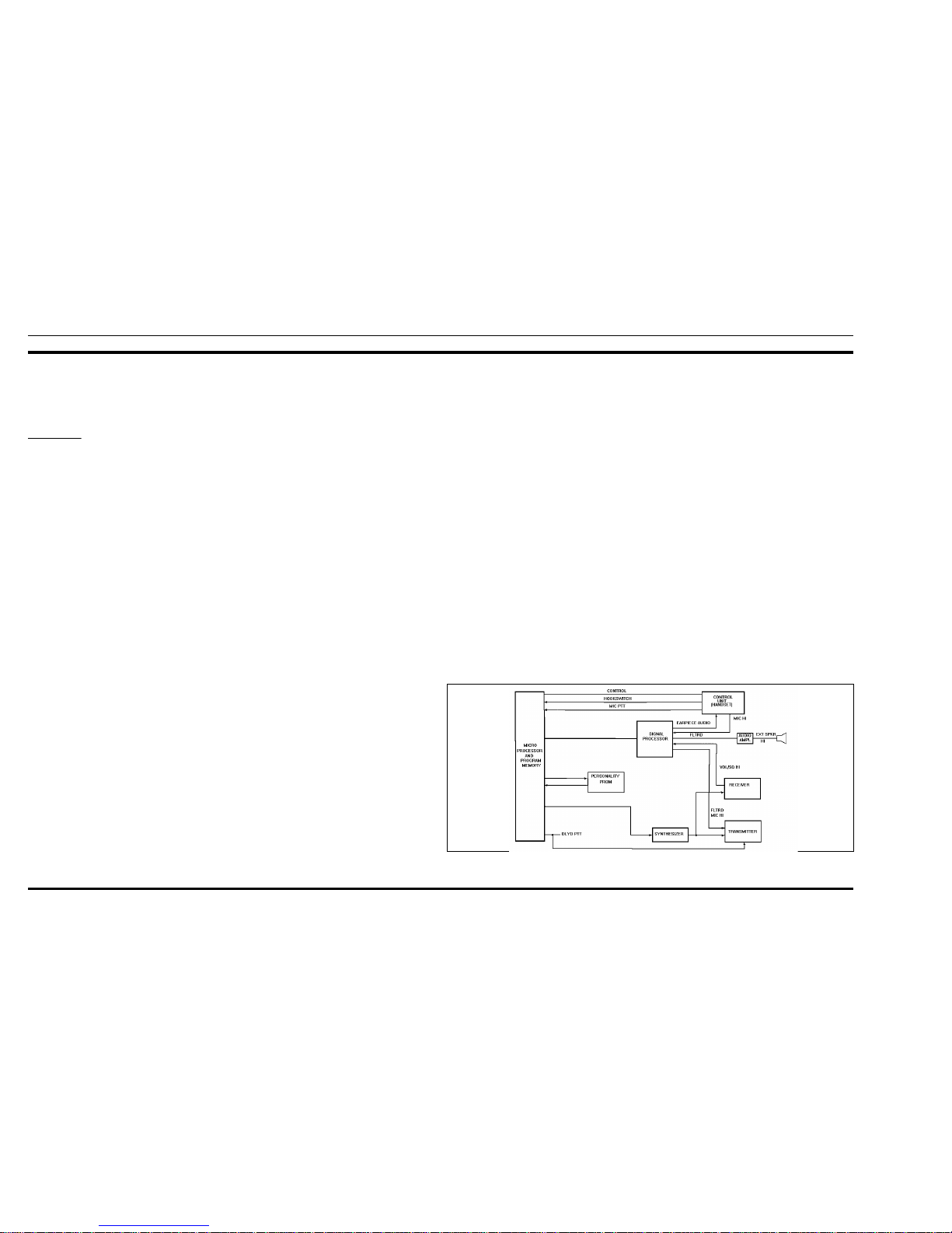
The GE-MARC VE trunked mobile radio system permits
improved access to available RF channels, freedom from annoyance by other users’ conversations and a degree of privacy
for the user. The trunked mobile radio system consists of a
repeater for each channel and the users’ mobile radio units. The
system uses tone signalling with each mobile being assigned
two and/or four tone group tone sequences. Groups of mobiles
are assigned the same tones, so that any unit can talk to all other
units in the same group. A Block Diagram is shown in Figure 1.
When originating a call, the mobile identifies an idle repeater
channel and interrogates it with a single burst of "busy" tone, the
repeater keys its transmitter and send s a burst of "acquisition"
tone back to the mobile unit. When the interrogating mobile
detects the acquisition tone, it then transmits its collect and group
tones, which the repeater regenerates for all idle mobile units on
the system.
The idle mobiles, which continually scan all channels, will
stop on the active channel if any of the programmed collect tones
are detected and wait for group tone(s).
If the correct tone sequence is detected, the mobiles will alert
the operator o f an incoming call and open their audio circuits. If
the correct sequence is not detected, the idle mobiles will resume
scanning the channels. Once the mobile is "locked" on a channel,
it will remain there until the repeater times out or the operator
terminates the call.
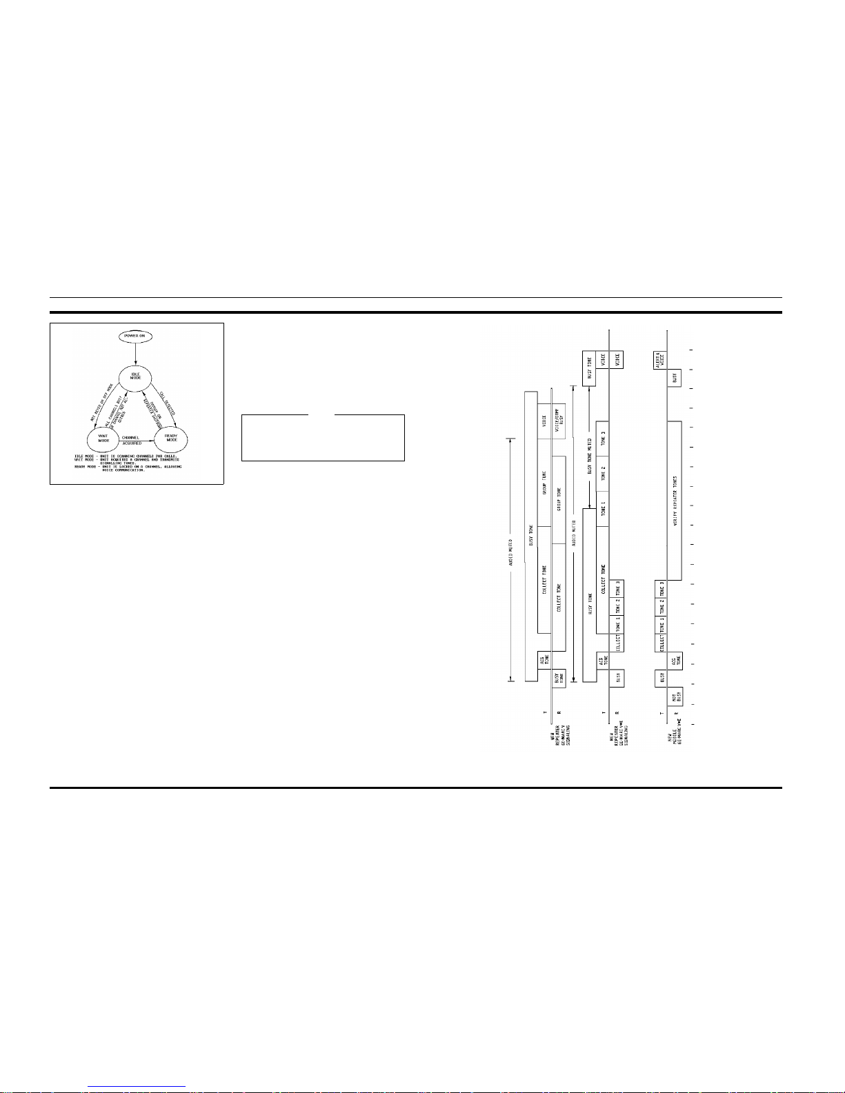
OPERATIONAL MODES
The radio will always be in one of three operational modes:
idle, wait, or ready. The three opertional modes and the conditions
that cause the radio to switch from one mode to another are shown
in Figure 2.
The radio enters th e idle mode when power is turned on and
begins scanning channels for incoming calls. The wait mode is
entered when the user places a call. The radio remains in the wait
mode until a channel is acquired, or if no channel is available. The
ready or convers ation mode is indicated by an alert tone and the
mode indicator on the control panel. A tone signalling Timing
Diagram is shown in Figure 3.
Sequence Flow Charts for each operational mode are sho wn
in Figures 4, 5, and 6.
IDLE MODE
When the radio is in the Idle Mode, the audio is muted and all
channels programmed for call decode are sequentially scanned for
an incoming call. An incoming call is identified by detecting one
of the collect tones programmed in the area. Upon receipt of a
collect tone, the mobile looks for a short interval for the group or
individual tones, providing that their collect tones are the same.
When no valid tone is found, the mobile will resume scanning the
channels for an incoming call.
If a group (or individual decode) tone is detected the mobile
then looks for busy tone for a 90 millisecond period. If four tones
are properly decoded, the mobile will then look for busy tone for
270 milliseconds.
When no valid tones are found, the mobile will resume
scanning for a call with the next cha nnel. When a busy tone is
found, the mob ile will enter the Ready Mode. If busy tone is not
detected, the mobile remains in the Idle Mode and continues
scanning channels looking for an incom i ng call.
Removing the handset from the hanger, pressing the PTT
switch or pressing the SEND key on the handset, will cause the
radio to enter the Wait Mode.
Figure 1 - GE-MARC VE Block Diagram
LBI-38696 LBI-38696
4
WAIT MODE
When the user enters the Wait mode, the display group is
checked to make sure it is a valid call-originate group. If it is not
valid, a low-frequency tone is heard for one second. If valid, the
radio will scan the call-originate frequencies for brief intervals
until it finds one with no busy tone on it. If no channel is free, the
radio, if programmed for this option, will activate the Call Retry
state and display "RETRYING" in the display. Retrying will
cause the radio to revert to the Idle mode and scan for an incomming call while trying to acquire a free re peater approximately
every 5 seconds for a 2 minute period. If the Retry option is not
enabled, the mobile will sound the low-frequency tone, and then
return to the Idle mode and display "BUSY".
If a channel with no busy tone is found, the mobile transmits
a burst of busy tone to acquire the repeater. The repeater then
responds with a burst of acquisition to ne. Upon receipt of the
acquisition tone, the mobile proceeds to transmit the group tones
(either two for four tones). If a four tone sequ ence is sent, the
mobile must detect all four tones and busy tone before entering
the Ready mode. If a two tone sequence is sent, the busy tone must
be present within 90 milliseconds of the last tone in order for the
radio to enter the Ready mode. If no busy tone is present, or if the
four tone sequence isn’t valid, the mobile will jump to the next
channel in the call originate set and check for busy tone as
described above.
READY MODE
When an incoming call has been detected, or an idle channel
has been acquired, the mobile enters the Ready mode. In this
mode, the audio and push-to-talk circuits are enabled, the speaker
is unmuted, and the operator is alerted an alert tone. The radio can
then be used in the conventional push-to-talk manner with the
radio remaining on the channel until the operator hangs up or the
repeater drops the busy tone, causing the unit to revert to Idle
mode.
GLOSSARY OF SYSTEM TERMS
Idle Mode
In the "standby" condition, the mobile is inactive, but prepared to call or be ca l led The trunked radios are ID LE until they
are turned off.
Wait Mode
In the "attempting origination" condition, the Wait mode is
entered from Idle mode (only) as the user presses the PTT switch
on the handse t, or comes "off-hook". If successful, the unit
becomes READY. Otherwise, the unit is IDLE Or IDLE/WAIT
after all channels are tried.
Ready Mode
In the "operating:" condition, Ready is entered from Idle
mode via Wait mode when calling, or directly from Idle when
called. Ready mode ends (the radio reverts to Idle) when the user
disconnects or with the loss of received Busy Tone from the
repeater. This normally occurs when the repeater shuts down after
communication is completed.
Busy T o ne
A tone of 3051.9 Hz is the standard busy tone. 2918 Hz is the
alternate busy tone. The busy tone modulates mobile and repeater
transmitters at a low level of 1 kHz deviation continuously. This
tone is filtered out of the received audio and is used to hold the
communication channel active. It also excludes other mobiles
from using the channel when a call is active.
Figure 2 - O pe r ational Modes
Figure 3 - Si gnal Timing
If a call is initiated and a sequence of five beeps is
sounded, the user cannot access the radio system due to
being out of mobil e recei ve ra nge or being inoper ative .
Any subsequent call will be ignored for 20 seconds.
NOTE
LBI-38696 LBI-38696
5
 Loading...