

Page 1
Users Guide
EXN401 & EXN410
Page 2

Users Guide
EXN401 & EXN410
.
Copyright
Ericsson AB - 2003 All Rights Reserved
Disclaimer
No part of this document may be reproduced in any form without the written
permission of the copyright owner.
The contents of this document are subject to revision without notice due to
continued progress in methodology, design and manufacturing. Ericsson shall
have no liability for any error or damage of any kind resulting from the use of
this document.
Abstract
This document describes the Ethernet DSL Access, and provides and overall
knowledge about the product.
This document is the Users Guide for the EXN401 & EXN410 and describes
the configuration and management of the Ethernet Gateway.
Trademark List
Interphase®, FibreView®, and the
Interphase logo
(i)chip™, SynWatch™m ENTIA™,
PowerSAN™, SlotOptomizer™,
iWARE™, iNAV™, and iSPAN™
-
These are registered trademark of
the Interphase Corporation
These are trademarks of the
Interphase Corporation
All other trademarks are the property
of their own manufacturers.
ii 1553-LZY 214 2655 C 2004-11-24
Page 3

END-USER LICENSE AGREEMENT
FOR ERICSSON AB SOFTWARE
IMPORTANT NOTICE TO USER–READ CAREFULLY
THIS END-USER LICENSE AGREEMENT FOR ERICSSON AB SOFTWARE (“AGREEMENT”) IS A LEGAL
AGREEMENT BETWEEN YOU (EITHER AN INDIVIDUAL OR SINGLE ENTITY) AND ERICSSON AB FOR THE
SOFTWARE PRODUCTS ENCLOSED HEREIN WHICH INCLUDES COMPUTER SOFTWARE AND PRINTED
MATERIALS (“SOFTWARE”). BY INSTALLING, COPYING, OR OTHERWISE USING THE ENCLOSED SOFTWARE,
YOU AGREE TO BE BOUND BY THE TERMS OF THIS AGREEMENT. IF YOU DO NOT AGREE TO THE TERMS AND
CONDITIONS OF THIS AGREEMENT, PROMPTLY RETURN, WITHIN THIRTY DAYS, THE UNUSED SOFTWARE TO
THE PLACE FROM WHICH YOU OBTAINED IT FOR A FULL REFUND.
The Software is protected by copyright laws and international copyright treaties, as well as other intellectual property laws and
treaties. The Software is licensed, not sold.
Grant of License: You are granted a personal license to install and use the Software on a single computer solely for internal use
and to make one copy of the Software in machine readable form solely for backup purposes.
Restrictions on Use: You may not reverse engineer, decompile, or disassemble the Software. You may not distribute copies of
the Software to others or electronically transfer the Software from one computer to another over a network. You may not use the
Software from multiple locations of a multi-user or networked system at any time. You may not use this software on any product
for which it was not intended. You may not use this software on any non-Ericsson product. LICENSEE MAY NOT RENT,
LEASE, LOAN, OR RESELL THE SOFTWARE OR ANY PART THEREOF.
Ownership of Software: Ericsson or its vendors retain all title to the Software, and all copies thereof, and no title to the
Software, or any intellectual property in the Software, is being transferred.
Software Transfer: You may permanently transfer all of your rights under this Agreement, provided you retain no copies, you
transfer all the Software, and the recipient agrees to the terms of this Agreement.
Limitation of Liability: NEITHER ERICSSON NOR ITS LICENSORS SHALL BE LIABLE FOR ANY GENERAL,
INDIRECT, CONSEQUENTIAL, INCIDENTAL, OR OTHER DAMAGES ARISING OUT OF THIS AGREEMENT EVEN IF
ADVISED OF THE POSSIBILITY OF SUCH DAMAGES.
Confidentiality: The Software is copyrighted and contains proprietary and confidential trade secret information of Ericsson and
its vendors. Licensee agrees to maintain the Software in confidence and not to disclose the Software to any third party without
the express written consent of Ericsson. Licensee further agrees to take all reasonable precautions to prevent access to the
Software by unauthorized persons.
Termination: Without prejudice to any other rights, Ericsson may terminate this Agreement if you fail to comply with any term
or condition of the Agreement. In such event you must destroy the Software together with all copies, updates, or modifications
thereof.
Export: You agree to comply with all export and re-export restrictions and regulations of the U.S. Department of Commerce or
other applicable U.S. agency. You must not transfer the Software to a prohibited country or otherwise violate any such
restrictions or regulations.
U.S. Government Restricted Rights: Use, duplication, or disclosure of the Software to or by the U.S. Government is subject to
restrictions as set forth in the applicable U.S. federal procurement regulations covering commercial/restricted rights software.
You are responsible for complying with the notice requirements contained in such regulations.
General: You acknowledge that you have read and understand this Agreement, and by installing and using the
Software you agree to be bound by the terms and conditions herein. You further agree that this is the complete and
exclusive Agreement between Ericsson and yourself. No variation of the terms of this Agreement or any different
terms will be enforceable against Ericsson unless agreed to in writing by Ericsson and yourself. The validity of this
Agreement and the rights, obligations, and relations of the parties hereunder shall be determined under the
substantive laws of the State of Sweeden. If any provision of this Agreement is held invalid, illegal, or
unenforceable, the remaining provisions shall in no way be affected or impaired thereby. All rights in the Software
not specifically granted in this Agreement are reserved by Ericsson.
iii
Page 4

Assistance
According to the Ericsson Service Agreement made, service and technical
assistance can be obtained accordingly. The consequent possibility for
downloading SW is obtained from
http://dxd.ericsson.se/cgi-bin/eda_authenticate.cgi/centre.html
Documentation updates
Documents are available according to agreement through the local Ericsson
Key Account Manager that can give access to the Customer Product
Information library:
http://cpi.al.sw.ericsson.se/alex
path: Multi-Service Networks (BMSN), Ethernet DSL Access.
and browse for the product on the following
Revision History
This User’s Guide is valid for EXN401 and EXN410 ATM to Ethernet
Converter. Other product versions, which include functions not described in
this manual, may be available.
iv
1553-LZY 214 2655 C 2004-11-24
Page 5

About this manual
Audience
This manual assumes that its audience has a general understanding of
computing and networking terminology.
Icon Conventions
Icons draw your attention to especially important information:
Note:
The Note icon indicates important points of interest related to the current
subject.
Caution!
The Caution icon brings to your attention those items or steps that, if not
properly followed, could cause problems in your machine’s configuration or
operating system.
Warning!
The Warning icon alerts you to steps or procedures that could be
hazardous to your health, cause permanent damage to the equipment, or
impose unpredictable results on the surrounding environment.
v
Page 6

Text conventions
The following conventions are used in this manual. Computer-generated text
is shown in typewriter font. Examples of computer-generated text are: program
output (such as the screen display during the software installation procedure),
commands, directory names, file names, variables, prompts, and sections of
program code.
Computer-generated text example
Commands to be entered by the user are printed in bold Courier type. For
example:
cd /usr/tmp
Pressing the return key “
assumed, when not explicitly shown. For example:
/bin/su
is the same as:
/bin/su ↵ Return
Required user input, when mixed with program output, is printed in bold
Courier type. References to UNIX programs and manual page entries follow
the standard UNIX conventions.
When a user command, system prompt, or system response is too long to fit
on a single line, it will be shown as
Do you want the new kernel moved into
\ vmunix?[y]
with a backslash at either the beginning of the continued line or at the end of
the previous line.
Return” at the end of the command line entry is
vi
1553-LZY 214 2655 C 2004-11-24
Page 7

.
Contents
Assistance iv
Documentation updates iv
Revision History iv
About this manual v
1 Introduction 1
1.1 Overview 1
1.2 Supported standards 1
1.3 Configuration Images 2
1.4 Configuration Methods 2
1.5 Management 3
1.6 Initial Configuration 3
2 Command Line Interface 4
2.1 Overview 4
2.2 Text Conventions 6
2.3 Using CLI Commands 7
2.3.1 Using Help 8
2.3.2 Command History 8
2.3.3 Accessing Command Modes 8
2.3.4 Session Time-Out 10
2.4 User EXEC Mode 11
2.4.1 enable 11
2.4.2 logout 11
2.4.3 disconnect 11
2.5 Privileged EXEC Mode 12
2.5.1 atm-format 12
1553-LZY 214 2655 C 2004-11-24 vii
Page 8

Introduction
2.5.2 buffers 12
2.5.3 session-timeout 13
2.5.4 watchdog 14
2.5.5 script 14
2.5.6 copy 15
2.5.7 update 16
2.5.8 reload 17
2.5.9 coldboot 17
2.5.10 clearconf 18
2.5.11 configure 18
2.5.12 disable 19
2.6 Global Configuration Mode 20
2.6.1 hostname 20
2.6.2 password 20
2.6.3 enable password 20
2.6.4 date 21
2.6.5 time 21
2.6.6 ip ftp username 22
2.6.7 ip ftp password 22
2.6.8 ip file server 23
2.6.9 ip gateway 23
2.6.10 oam-nodeid 23
2.6.11 lacp 24
2.7 Controller Configuration Mode 25
2.7.1 Entering Mode 25
2.7.2 Commands 25
2.8 Ethernet Interface Configuration Mode 29
2.8.1 Entering Mode 29
2.8.2 Commands 29
2.9 VC Class Configuration Mode 36
2.9.1 Overview 36
2.9.2 Entering Mode 36
2.9.3 Commands 36
viii 1553-LZY 214 2655 C 2004-11-24
Page 9

IntroductionContents
2.9.4 Removing a VC Class 48
2.10 ATM Interface Configuration Mode 49
2.10.1 Overview 49
2.10.2 Entering Modes 50
2.10.3 ATM Interface Configuration Commands 51
2.10.4 ATM VP Configuration Commands 54
2.10.5 ATM PVC Configuration Commands 57
2.10.6 ATM PVC Range Configuration Commands 61
2.11 Management Configuration Mode 64
2.11.1 Overview 64
2.11.2 Entering Mode 64
2.11.3 Commands 65
2.11.4 Binding an Interface to Management 67
2.11.5 Removing a Management entity 68
2.12 Failover Configuration Mode 69
2.12.1 Overview 69
2.12.2 Entering Mode 69
2.12.3 SONET Specific Commands 70
2.12.4 Gigabit Ethernet Specific Commands 71
2.12.5 Show Commands 72
2.12.6 Other Commands 73
2.12.7 Removing a Failover group 74
2.13 Link Aggregation Configuration Mode 75
2.13.1 Overview 75
2.13.2 Entering Mode 75
2.13.3 Commands 76
2.13.4 Removing a Link Aggregation Group 78
2.14 General Commands 79
2.14.1 ping 79
2.14.2 show 79
3 Bridging 82
3.1 Overview 82
1553-LZY 214 2655 C 2004-11-24
ix
Page 10

Introduction
3.1.1 What is a Bridge 82
3.1.2 Types of Bridges 82
3.1.3 VLANs 82
3.1.4 Frames Format 83
3.2 EXN400 Bridging Support 86
3.2.1 Supported Interfaces 86
3.2.2 Maximum Number of Bridges 86
3.2.3 Types of Bridge 86
3.2.4 VLAN-Aware Bridge 86
3.2.5 Learning 87
3.2.6 Filtering 87
3.2.7 Force Forwarding 88
3.2.8 Management 88
3.2.9 Bridging process 88
3.2.10 Example: Ethernet-to-ATM – no VLAN – ATM VC Multiplexing 90
3.2.11 Example: ATM-to-Ethernet – no VLAN – ATM LLC/SNAP
Encapsulation 90
3.2.12 Example: Ethernet-to-ATM – VLAN – ATM LLC/SNAP
Encapsulation 91
3.2.13 Example: ATM-to-Ethernet – VLAN – ATM VC Multiplexing 91
3.3 VLAN Priority Mapping 92
3.3.1 Weighted Fair Queueing Mechanism 93
3.4 Command Line Interface 95
3.4.1 Subscriber Policy Configuration Mode 95
3.4.2 Priority Table Configuration Mode 102
3.4.3 ATM PVC Group Configuration Mode 104
3.4.4 PVC Range Group Configuration Mode 108
3.4.5 Bridge Configuration Mode 112
3.5 Configuration Samples 126
3.5.1 Configuring a Transparent MAC Bridge 126
3.5.2 Configuring a VLAN-Aware Bridge 128
4 SNMP Management 130
4.1 Overview 130
x 1553-LZY 214 2655 C 2004-11-24
Page 11

IntroductionContents
4.2 Configuring SNMP Management 130
4.2.1 Enabling Reception of SNMP Requests 130
4.2.2 Setting the Contact, Name, and Location 131
4.2.3 Configuring a TRAP client 133
4.3 Alarm Notification 134
4.4 Notes on RFC2233 134
4.5 Notes on RFC2737 136
4.6 Notes on RFC1757 136
4.7 Notes on RFC2515 136
4.8 Notes on RFC2558 136
4.9 Notes on RFC2558 136
5 Initial Configuration and Configuration Samples 138
5.1 Initial Configuration 138
5.1.1 Configuring EXN400 Name 138
5.1.2 Setting Date and Time 138
5.1.3 Enabling Privileged EXEC password 139
5.1.4 Configuring ATM format 139
5.1.5 Configuring System Buffer Pool 139
5.2 Configuring Failover 140
5.2.1 Configuring Gigabit Ethernet Failover 140
5.2.2 Configuring SONET Failover 140
5.3 Configuring Management 141
5.3.1 Configuring Management through Fast Ethernet 141
5.3.2 Configuring Management through Fast Ethernet using VLAN 141
5.3.3 Configuring Management on an IP over ATM Channel 142
5.3.4 Configuring Management on an Ethernet over ATM Channel 143
5.4 Configuring FTP Connection 144
6 Command list, description and index 145
6.1 Overview 145
6.2 Global commands 145
6.2.1 Available Commands 145
1553-LZY 214 2655 C 2004-11-24
xi
Page 12

Introduction
6.3 Quick Reference 151
7 Configuration Guidelines 154
7.1 Schematic Configuration Overview 154
7.2 Accessing the EXN400 154
7.2.1 Default settings for EXN 400 series 155
7.3 Configuration order and examples 156
7.3.1 Clear previous configuration in EXN400 157
7.3.2 Enter the “Global configuration mode” of the EXN400 157
7.3.3 Define "Hostname and Password" for entering this EXN401 157
7.3.4 Create a "Subscriber policy" object 157
7.3.5 Create a "Management" object 157
7.3.6 Define where the ftp file server for software upgrade is incl.
UserID and Password 158
7.3.7 Create a bridge object 158
7.3.8 Initilize the ATM 0 port 158
7.3.9 Initilize the FastEthernet 1 port 158
7.3.10 Connect the management-object and the fastEthernet 1 port to
the bridge-object 158
7.3.11 Define the VC-classes 159
7.3.12 Define the PVC's in the ATM 0 interface, ubr (data1) is set as
the default service class 159
7.3.13 Check how this looks in the connected bridge 160
7.3.14 Define the "virtual ports" in the bridge bridge1 on the
fastEthernet 1 port side 160
7.3.15 Define the "virtual ports" in the bridge bridge1 on the ATM 0
port side 161
7.3.16 Set the sonet interface to “clock source internal” in the EXN400 162
7.3.17 Show all configuration in the EXN400 162
7.3.18 Save configuration in the EXN400 162
7.3.19 Restart the EXN400 162
Acronyms and Abbreviations 163
Reference List 164
xii 1553-LZY 214 2655 C 2004-11-24
Page 13

IntroductionContents
Index 165
1553-LZY 214 2655 C 2004-11-24
xiii
Page 14

Page 15
1 Introduction
1.1 Overview
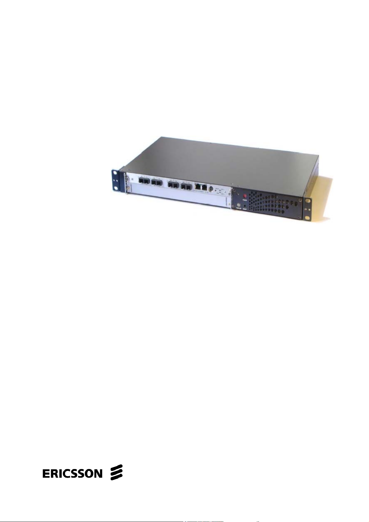
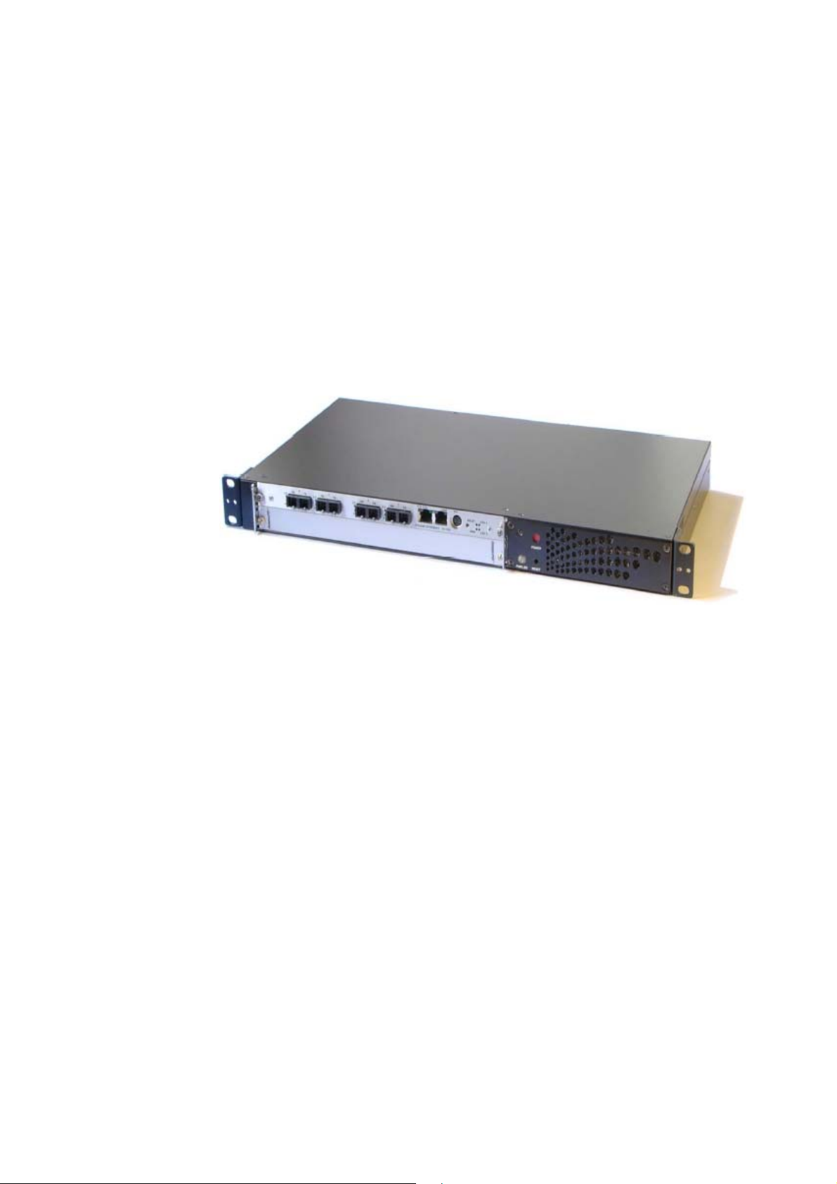
The EXN400 Ethernet Gateway; see Figure 1 on page 1 is a stand-alone
replaceable unit in a 1U height configuration (pizza box) that provides ATM
to Ethernet processing between various interfaces.
Introduction
Figure 1 EXN410; Ethernet Gateway
As an off-the-shelf product, the EXN400 is manageable without additional
software add-ons. Management includes configuration and monitoring.
At initial installation, the user can access the EXN400 only through a TTY
console (parameters are 9600 baud, 8 data bits, 1 stop bit, no parity, no
flow control) or via Telnet by using the default settings mentioned in section
7.2.1 on page 155.
After management configuration, the user can also access the EXN400 on
a Telnet session (for more information see Management Configuration
Mode, section 2.11 on page 64 and Configuring Management, 5.3 on page
141).
1.2 Supported standards
IEEE and IETF Standards Compatibility:
IEEE 802.3u Fast Ethernet •
• • IEEE 802.3ab 1000BaseT
IEEE 802.1Q-VLAN, IEEE 802.eac
1553-LZY 214 2655 C 2004-11-24
1
Page 16

Introduction
IEEE 802.3 LAN per 802.3, 802.3ab •
•
IEEE 802.3ad Link Aggregation
IETF Standards Compatibility:
•
RFC 2684 Multiprotocol encapsulation over ATM AAL5
ITU Standards Compatibility:
•
ITU-T I.432.1, I.432.2 B-ISDN user-network interface – Physical layer
specification
•
ITU-T I.361 B-ISDN ATM layer specification
•
ITU-T I.363.5 B-ISDN ATM adaptation layer specification: Type 5 AAL
•
ITU-T I.371 Traffic control and congestion control in B-ISDN
•
ITU-T I.371.1 Guaranteed frame rate ATM transfer capability
•
ITU-T I.610 B-ISDN operation and maintenance principles and
functions
1.3 Configuration Images
There are three images of the software configuration:
•
The running configuration is the configuration currently running. It is
stored in RAM. Therefore any change in configuration will not be taken
into account at next boot unless the running configuration is saved.
•
The startup configuration is the configuration that is taken into account
at boot time. It is stored in FLASH and can be updated.
•
The backup configuration is a copy of an operational configuration that
can be reactivated at any time. When configuration is saved in the
startup configuration, the previous startup configuration becomes the
backup configuration.
The software configuration can be downloaded from or saved to a
configuration file on an FTP/TFTP server. This file is not in a humanreadable format and should not be modified by the user.
1.4 Configuration Methods
Configuration is possible by using any of the following methods:
•
Entering commands on the Command line interface (CLI) through TTY
or remote shell
2 1553-LZY 214 2655 C 2004-11-24
Page 17

Preparing a script file including all the CLI commands, copying it on an
•
FTP server, and downloading the script file on the EXN400 by running
the script CLI command (for more information on script command,
see “script”, section 2.5.5 on page 14)
•
Downloading a configuration file on the EXN400 from an FTP server by
running the copy CLI command and rebooting to take the new
configuration into account (see “copy”, section 2.5.6 on page 15)
1.5 Management
A management entry point should be configured to:
•
Perform an FTP/TFTP connection
•
Run the ping command
Introduction
•
Enable a telnet access to the EXN400
•
Enable SNMP management
Management can be configured through:
•
A single Ethernet interface or ATM PVC (for more information, see
Management Configuration Mode, section 2.11 on page 64)
•
A bridge (for more information, see Management Configuration Mode,
section 2.11 on page 64)
For a bridge, management will be available through any interface and/or
ATM PVC bound
to the bridge.
1.6 Initial Configuration
At first use, it is strongly recommended to configure:
•
The EXN400 name
•
The date and time
•
The Privileged EXEC password (if needed)
•
The ATM format
•
The system buffer pool
1553-LZY 214 2655 C 2004-11-24
3
Page 18

Command Line Interface
2 Command Line Interface
2.1 Overview
The Command Line Interface (CLI) is available through either a TTY
console or a Telnet session. Only one Telnet session can be open on an
EXN400 at a given time. To enable telnet access, at least one management
entry point must be configured (for more information, see Management
Configuration Mode, section 2.11 on page 64).
Several access levels are available:
User EXEC level: Only certain commands to view the EXN400 status
•
are available.
• • Privileged EXEC level: All the commands to view and configure the
EXN400 are available. A password may be required. Only one session
can enter Privileged EXEC level at a given time.
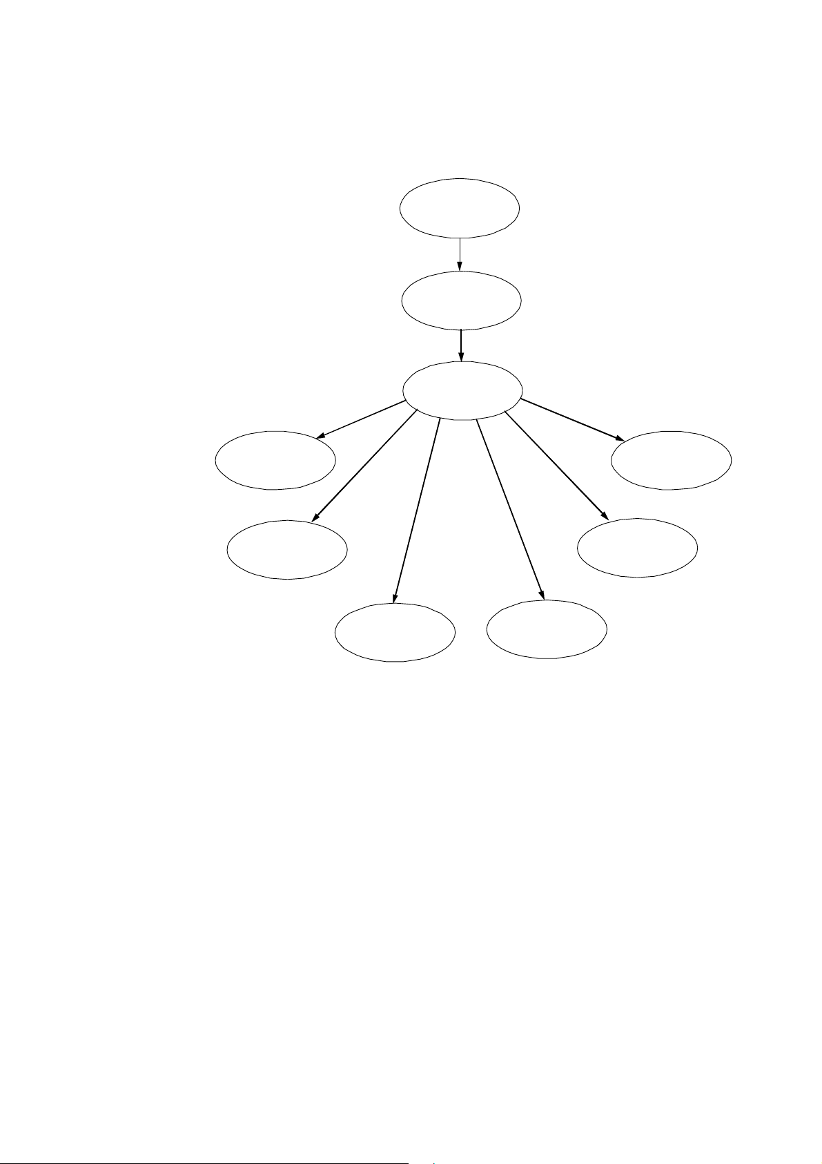
The EXN400 configuration exists in Global configuration and several
lower level configurations.
To illustrate this, several configuration modes are organized as shown in
Figure 2 on page 5.
4 1553-LZY 214 2655 C 2004-11-24
Page 19
Command Line Interface
User EXEC
Mode
Privileged
EXEC Mode
Global
Configuration
Controller
Configuration
Management
Configuration
VC Class
Configuration
Subscriber
Configuration
Interface
Configuration
Bridge
Configuration
Policy
Figure 2 Configuration Mode Organization
The command line prompt identifies both the EXN400 name and the
command mode. The last character in the command prompt identifies the
access level, that is,
$ for a User EXEC level and # for a Privileged EXEC
level.
Example:
MyBox(config-if)#
1553-LZY 214 2655 C 2004-11-24
5
Page 20

Command Line Interface
2.2 Text Conventions
Command descriptions use the following conventions:
boldface font Commands and keywords are in boldface. •
•
plain font Parameter values are in plain.
•
{...} Keywords or variables are required.
•
[...] Keywords or variables are optional.
•
x | y Choice between two keywords or variables.
•
<key> Keyboard character or sequence of characters.
6 1553-LZY 214 2655 C 2004-11-24
Page 21

2.3 Using CLI Commands
The Command Line Interface (CLI) is case-sensitive. •
•
Abbreviated commands: You can abbreviate keywords by entering at
least sufficient leading characters to uniquely identify the desired
keyword.
•
The ? key: Use the ? key at any time to see all the choices you can
enter next. When you enter the ? key, all available choices are
displayed. The system again displays the command you already
entered.
•
The <backspace> key can be used to delete the character immediately
preceding the cursor.
Command Line Interface
•
The <enter> key is used to execute the entered command.
•
The <tab> key and <space> key can be used to complete the current
keyword (if possible). It applies only to well-known keywords and not to
names of entities created by the user.
•
The <up-arrow> key can be used to display the previous command in
history.
•
The <down-arrow> key can be used to display the next command in
history.
•
The <left-arrow> and <right-arrow> keys can be used to move the
cursor back and forth in the command line.
•
The <ESC+B> keys can be used to move the cursor back one word.
•
The <ESC+F> keys can be used to move the cursor forward one word.
•
The <CTRL+A> keys can be used to move the cursor to the beginning
of the command line.
•
The <CTRL+E> keys can be used to move the cursor to the end of the
command line.
•
The <CTRL+C> keys can be used to abort a command line.
•
One <space> character cannot be followed by another <space>
character. The second one is discarded by the CLI.
•
The no keyword: For most configuration commands, the no keyword
can be inserted at the beginning of the command line to negate a
command or to restore its default setting.
•
Names of entities created by the user are alphanumeric strings. They
can contain any character in the sets [a-z], [A-Z], [0-9]. The underscore
character ‘_’ is also accepted. In addition, names of entities of the
same type should be carefully chosen. For example, if an entity named
1553-LZY 214 2655 C 2004-11-24
7
Page 22

Command Line Interface
thename exists, it will not be possible to define a new entity named
thenam.
2.3.1 Using Help
The system CLI provides a variety of useful context-sensitive help features:
? Lists all keywords applicable to the
•
•
help Displays a brief description of the help
•
partial-keyword?
•
partial-keyword<tab> Completes the partial keyword (if
current command mode
system
Lists the keywords that begin with a
certain character string
possible)
•
command <space>? Lists the set of all valid
2.3.2 Command History
The CLI maintains a command history for each command mode. You can
navigate through command history by using the up and down arrows.
2.3.3 Accessing Command Modes
Table 1 Command Mode Access
Mode
Privileged
EXEC
Global
Configuration
Access
From
User EXEC
Privileged
EXEC
Command Description
enable
configure
next available choices
Access to Privileged EXEC Mode.
To exit this mode:
- disable or exit to return to User EXEC
Access to Global Configuration Mode.
New prompt: (config)
To exit this mode:
- exit or Ctrl+Z to return to Privileged
EXEC
Controller
configuration
Global
Configuration
controller
To configure a SONET interface
New prompt: (config-controll)
To exit this mode:
- exit or abort to return to Global
Configuration
- Ctrl+Z to return to Privileged EXEC
8 1553-LZY 214 2655 C 2004-11-24
Page 23

Command Line Interface
Mode
Interface
configuration
ATM VC
class
configuration
Management
configuration
Failover
configuration
Link
aggregation
configuration
Access
From
Global
Configuration
Global
Configuration
Global
Configuration
Global
configuration
Global
configuration
Command Description
interface
vc-class atm
management
failover
link-
aggregation
To modify other types of interfaces
(ATM, FastEthernet, GigabitEthernet)
New prompt: (config-if)
To exit this mode:
- exit or abort to return to Global
Configuration
- Ctrl+Z to return to Privileged EXEC
To create or modify a set of
preconfigured VC parameters.
New prompt: (config-vc-class)
To exit this mode:
- exit or abort to return to Global
Configuration
- Ctrl+Z to return to Privileged EXEC
To create or modify a management
entry point.
New prompt: (
To exit this mode:
- exit or abort to return to Global
Configuration
- Ctrl+Z to return to Privileged EXEC
To create or modify a link aggregation
group.
New prompt: (
To exit this mode:
- exit or abort to return to Global
Configuration
- Ctrl+Z to return to Privileged EXEC
To create or modify a failover group.
New prompt: (
To exit this mode:
- exit or abort to return to Global
Configuration
- Ctrl+Z to return to Privileged EXEC
config-mngt)
config-link-agg)
config-flvr)
Subscriber
Policy
configuration
Bridge
configuration
1553-LZY 214 2655 C 2004-11-24
Global
Configuration
Global
Configuration
subscriberpolicy
bridge
To create or modify a subscriber policy.
New prompt: (config-bridge)
To exit this mode:
- exit to return to Global Configuration
- Ctrl+Z to return to Privileged EXEC
To create or modify a bridge.
New prompt: (config-bridge)
To exit this mode:
- exit to return to Global Configuration
- Ctrl+Z to return to Privileged EXEC
9
Page 24

Command Line Interface
2.3.4 Session Time-Out
Since the number of sessions is limited (one session on TTY console and
one telnet session) and the access to Privileged EXEC level is exclusive,
the EXN400 automatically disconnects any session after a period of
inactivity, that is:
For a telnet access, the session is closed. •
• For the TTY console, the session returns to User EXEC level.
The session time-out is 900 seconds by default but can be changed in
Privileged EXEC mode.
10 1553-LZY 214 2655 C 2004-11-24
Page 25

2.4 User EXEC Mode
2.4.1 enable
Description This command is used to enter into Privileged EXEC mode.
If a password is enabled, user is requested to enter it.
Syntax enable
Default none
Modes User EXEC
Example EXN400$ enable
Command Line Interface
2.4.2 logout
Description This command is used to disconnect a telnet session. This
command is available only for a telnet session.
Syntax logout
Default none
Modes User EXEC, Privileged EXEC
Example EXN400$ logout
2.4.3 disconnect
Description This command is used to force disconnection of a telnet
session. This command is available only for the console session. You can
see if a telnet session is engaged by running the show session comand.
Syntax disconnect
Default none
Modes User EXEC
Example EXN400$ disconnect
1553-LZY 214 2655 C 2004-11-24
11
Page 26

Command Line Interface
2.5 Privileged EXEC Mode
2.5.1 atm-format
Description This command is used to configure the ATM format between
Network Network Interface (NNI) and User Network Interface (UNI). Once
you change the settings, no further configuration is allowed and you will be
asked to save your configuration and reboot the system. Note that this
parameter is part of the system startup configuration and is not reset by the
clearconf command without the all option.
Syntax atm-format [nni|uni]
nni Selects the NNI format.
uni Selects the UNI format.
If no parmeter is specified, the command displays the current ATM format.
Default NNI
Show show atm-format
Modes Privileged EXEC
Example To configure the ATM format to UNI:
EXN400# atm-format uni
2.5.2 buffers
Description This command is used to configure the system buffer pool.
User can specify the buffer size and the system automatically computes the
number.
The buffers are used to receive and transmit data on any communicating
channel (ATM PVC, Ethernet interface). Each time a new channel is
defined, some buffers are reserved. The number of buffers reserved for
each channel depends on the size of the transmit queue for this channel.
The transmit queue size can be configured by using the tx-queue-size
command.
The buffer size limits the Maximum Transmit Unit (MTU) size. One buffer
must be able to contain the largest MTU and an extra 120-bytes overhead.
12 1553-LZY 214 2655 C 2004-11-24
Page 27

Command Line Interface
You should keep in mind that increasing the buffer size results in reducing
the number of buffers, and thus, the number of communicating channels
that can be supported.
Once you change the system buffer pool settings, no further configuration
is allowed and you will be asked to save your configuration and reboot the
system. Note that this parameter is part of the system startup configuration
and is not reset by the clearconf command without the all option.
Current settings can be displayed by using the show buffers command.
Syntax buffers {size}
size The new buffer size. It must be a multiple of 256, in the
range [1792-64256]. It must also contain the largest MTU
and an extra 120-bytes overhead.
Default 1792
Show show buffers
Modes Privileged EXEC
Example To configure the buffer size to 2304:
EXN400# buffers 2304
2.5.3 session-timeout
Description This command is used to change the inactivity timeout for
any session.
Syntax [no] session-timeout [value]
value The new assigned timeout in seconds. Value 0 means no
inactivity timeout.
session-timeout value Change the inactivity timeout.
session-timeout Display the current timeout value.
no session-timeout Disable inactivity timeout.
Default 900 seconds
Show session-timeout
Modes Privileged EXEC
Example To configure the session timeout to one hour:
EXN400# session-timeout 3600
1553-LZY 214 2655 C 2004-11-24
13
Page 28

Command Line Interface
2.5.4 watchdog
Description This command is used to enable or disable the watchdog
mechanism. When the watchdog is enabled, it monitors software activity
and when it detects a failure, it automatically reboots the system.
Syntax [no] watchdog
watchdog Enable watchdog.
no watchdog Display watchdog.
Default Disabled
Show show watchdog
Modes Privileged EXEC
Example To enable watchdog:
EXN400# watchdog
2.5.5 script
Description This command is used to download a script file from the FTP
server and run it. A script file is a text file. Each line is a command as if it
would be entered on the TTY console or Telnet session. Some comment
lines, starting with a pound sign (
script file to improve the readability.
Syntax script {ftp:filename | tftp:filename}
filename Name of the script file on the FTP/TFTP server.
The FTP connection is defined by using:
The FTP username defined using the ip ftp username command
•
(for more information, see “ip ftp username” section 2.6.6 on page 22)
•
The FTP password defined using the ip ftp password command
(for more information, see “ip ftp password” section 2.6.7 on page 22)
•
The FTP server location defined using the ip file server
command (for more information, see “ip file server” section 2.6.8 on
page 23).
#), or blank lines can be inserted in the
The TFTP connection uses the TFTP server location defined using the ip
file server command (for more information, see “ip file server” section
2.6.8 on page 23).
Default None
14 1553-LZY 214 2655 C 2004-11-24
Page 29

Modes Privileged EXEC
Requirement Need a management entry point since FTP/TFTP is used.
Example To download and run the script file scrconf.txt located in
the directory script on the FTP server:
EXN400# script ftp:script/scrconf.txt
Requirement Need a management entity since FTP is used. This management entity must have an IP address and mask in the same sub-network as
the FTP server.
2.5.6 copy
The copy command in Privileged EXEC mode can be used to:
Command Line Interface
Copy any configuration image to an FTP server •
•
COPY a startup configuration image from an FTP server
•
Copy the running configuration into the startup configuration
•
Restore a backup configuration
Description This command is used to save a configuration to ROM or to
load/copy a configuration from/to an FTP server.
Syntax copy src-config dest-config
src-config and dest-config are one of the following:
backup-config A backup configuration
running-config The current running configuration
startup-config The startup configuration stored in FLASH
ftp:filename filename is the name of the file on the FTP server to
upload or download.
ftp:filename filename is the name of the file on the TFTP server
to upload or download.
The FTP connection is defined by using:
•
The FTP username defined using the ip ftp username command
(for more information, see “ip ftp username” section 2.6.6 on page 22)
•
The FTP password defined using the ip ftp password command
(for more information, see “ip ftp password” section 2.6.7 on page 22)
1553-LZY 214 2655 C 2004-11-24
15
Page 30

Command Line Interface
The FTP server location defined using the ip file server
•
command (for more information, see “ip file server” section 2.6.8 on
page 23).
The TFTP connection uses the TFTP server location defined using the ip
file server command (for more information, see “ip file server” section
2.6.8 on page 23).
The supported combinations are:
•
copy running-config startup-config
•
copy running-config {ftp:filename | tftp:filename}
•
copy startup-config {ftp:filename | tftp:filename}
•
copy backup-config {ftp:filename | tftp:filename}
•
copy backup-config startup-config
•
copy {ftp:filename | tftp:filename} startup-config
Default None
Modes Privileged EXEC
Requirement Need a management entry point since FTP/TFTP is used.
Example To save running configuration to startup configuration to be
taken into account on next reboot:
EXN400# copy running-config startup-config
Example To save running configuration on an FTP server, in file
named backup located in directory config:
EXN400# copy running-config ftp:config/backup
2.5.7 update
Description This command is used to update the EXN400 internal
software. The EXN400 internal software is supplied by Ericsson as a binary
file. After running this command, the EXN400 is automatically rebooted.
Syntax update {ftp: filename | tftp: filename}
filename Name of the file that contains the new EXN400 internal
software.
16 1553-LZY 214 2655 C 2004-11-24
Page 31

Command Line Interface
The FTP connection is defined by using:
The FTP username defined using the ip ftp username command
•
(for more information, see “ip ftp username” section 2.6.6 on page 22)
•
The FTP password defined using the ip ftp password command
(for more information, see “ip ftp password” section 2.6.7 on page 22)
•
The FTP server location defined using the ip file server
command (for more information, see “ip file server” section 2.6.8 on
page 23).
The TFTP connection uses the TFTP server location defined using the ip
file server command (for more information, see “ip file server” section
2.6.8 on page 23).
Default None
Modes Privileged EXEC
Requirement Need a management entry point since FTP/TFTP is used.
Example To download a new version of the software from an FTP
server that is stored in the file named last located in
directory release :
EXN400# update ftp:release/last
2.5.8 reload
Description This command is used to initiate a software reboot of the
EXN400. On reboot, the startup configuration is applied. If you made any
change in the configuration but did not save your configuration into startup
configuration before rebooting, your modifications will be lost.
Syntax reload
Default None
Modes Privileged EXEC
Example EXN400# reload
2.5.9 coldboot
Description This command is used to initiate a complete cold boot of the
EXN400. The difference with the reload command is that coldboot will not only restart the software system but first run Power-On Self Tests (POST). On cold boot, the startup configuration is applied. If you made any
1553-LZY 214 2655 C 2004-11-24
17
Page 32

Command Line Interface
change in the configuration but did not save the configuration into startup
configuration before coldbooting, the modifications will be lost.
Syntax coldboot
Default None
Modes Privileged EXEC
Example EXN400# coldboot
2.5.10 clearconf
Description This command is used to reset the startup configuration.
After running this command, the EXN400 is automatically rebooted by
using coldboot. On reboot, the startup configuration is applied. Since it
has been reset before reboot, no configuration will be done. After a
software update, you may be asked to run the clearconf command with
the all option to also reset the system startup configuration. Note that the
ATM format (see section 2.5.1 on page 12) and the buffers size (see
section 2.5.2 on page 12) parameters are part of the system startup
configuration. Therefore, they are not reset by the clearconf command
without the all option.
Syntax clearconf [all]
clearconf Reset all user configurations.
Clearconf all Reset all configurations.
Default None
Modes Privileged EXEC
Example EXN400# clearconf
2.5.11 configure
Description This command is used to enter into Global Configuration
mode.
Syntax configure
Default none
Modes Privileged EXEC
Example EXN400# configure
18 1553-LZY 214 2655 C 2004-11-24
Page 33

2.5.12 disable
Description This command is used to exit the Privileged EXEC mode and
return to User EXEC mode.
Syntax disable
Default None
Modes Privileged EXEC
Example EXN400# disable
Command Line Interface
1553-LZY 214 2655 C 2004-11-24
19
Page 34

Command Line Interface
2.6 Global Configuration Mode
2.6.1 hostname
Description This command is used to assign a name to the EXN400. The
new name is included in the next displayed prompt.
Syntax hostname name
name The new assigned name. It can be up to 15 alphanumeric
characters long.
Default No name
Modes Global Configuration
Example To change the EXN400 name into hello:
EXN400(config)# hostname hello
2.6.2 password
Description This command is used to change the password that is
required to enter Privileged EXEC mode. After a change, do not forget to
save the current configuration into startup configuration to take the new
password into account on next reboot.
Syntax password passwd
passwd The new assigned password. It can be up to 15
alphanumeric characters long. The ‘?’ character is not
accepted.
Default None
Modes Global Configuration
Example To change the password into comein:
EXN400(config)# password comein
2.6.3 enable password
Description This command is used to enable/disable password to enter
Privileged EXEC mode. After a change, do not forget to save the current
configuration into startup configuration.
20 1553-LZY 214 2655 C 2004-11-24
Page 35

Command Line Interface
Syntax [no] enable password
enable password Enable password to enter Privileged EXEC
mode.
no enable password Disable password to enter Privileged EXEC
mode.
Default: Password disabled
Show show config all
Modes Global Configuration
Example To enable the password:
EXN400(config)# enable password
2.6.4 date
Description This command is used to set the date.
Syntax date [yyyy/mm/dd]
yyyy/mm/dd year/month/day
If no parameter is entered, it displays the current EXN400 date.
Default None
Show show time
Modes Global Configuration
Example To set the date to the 17 Marchl 2004:
EXN400(config)# date 2004/03/17
2.6.5 time
Description This command is used to set the time.
Syntax time [hh:mm:ss]
hh:mm:ss hours:minutes:seconds
If no parameter is entered, it displays the current EXN400 time.
Default None
1553-LZY 214 2655 C 2004-11-24
21
Page 36

Command Line Interface
Show show time
Modes Global Configuration
Example To set the time to 11 hours 23 minutes and 30 seconds:
EXN400(config)# time 11:23:30
2.6.6 ip ftp username
Description This command is used to set the user name for an FTP
download.
Syntax ip ftp username ftp-username
ftp-username The user name defined on the FTP server. The
‘?’ character is not accepted.
no ip ftp username Remove username
Default None
Show show ip
Modes Global Configuration
Example To set the FTP username to
EXN400(config)# ip ftp username guest
2.6.7 ip ftp password
Description This command is used to set the password for an FTP
download.
Syntax ip ftp password ftp-password
ftp-password The password defined on the FTP server. The
no ip ftp password Remove password
Default None
guest:
‘?’ character is not accepted.
Modes Global Configuration
Example To set the FTP password to guest:
EXN400(config)# ip ftp password guest
22 1553-LZY 214 2655 C 2004-11-24
Page 37

2.6.8 ip file server
Description This command is used to specify the IP address for the
FTP/TFTP server.
Syntax ip file server ipAddr
Command Line Interface
ipAddr
The IP address in the dotted form
no ip ftp server Remove IP address for the FTP/TFTP server
Default None
Show show ip
Modes Global Configuration
Example To set the FTP/TFTP server IP address to 192.134.45.1:
EXN400(config)# ip file server 192.134.45.1
2.6.9 ip gateway
Description This command is used to specify the IP address for the
default gateway.
Syntax ip gateway ipAddr
ipAddr The IP address in the dotted form.
no ip gateway Remove IP address for the gateway
Default None
Show show ip
Modes Global Configuration
Example To set the IP address of the default gateway to 192.134.45.1:
EXN400(config)# ip gateway 192.134.45.1
2.6.10 oam-nodeid
Description The node ID is used to identify the equipment on ATM for
OAM loopback exchanges. This value can be used by other ATM devices
to identify this equipment, address OAM loopback cells to it, and expect
responses from it. The node ID is a 16-byte octet string. After a change,
you must save the current configuration into startup configuration.
Syntax oam-nodeid [nodeId]
1553-LZY 214 2655 C 2004-11-24
23
Page 38

Command Line Interface
nodeId The node Id value. It is a string starting with 0x representing
the 16-byte and right justified.
If no parameter is specified, the command displays the current node ID
value.
Default All zeros
Show show oam-nodeid
Modes Global Configuration
Example To set the node ID to
x00000000000000000000000000012345:
EXN400(config)# oam-nodeid 0x12345
2.6.11 lacp
Description This command is used to enable/disable Link Aggregation
Control Protocol (LACP) on any configured link aggregation group. For
more information on link aggregation, see Link Aggregation Configuration
Mode section 2.13 on page 75.
Syntax [no] lacp
Default: Enabled
Show show lacp
Modes Global Configuration
Example To disable LACP:
EXN400(config)# no lacp
24 1553-LZY 214 2655 C 2004-11-24
Page 39

2.7 Controller Configuration Mode
2.7.1 Entering Mode
From Global Configuration mode, enter the following command:
controller controller_family controller_name
controller_family Defines the type of controller to configure. The
only available family is sonet.
controller_name Specifies which controller to configure. The name
consists of the port number (as it appears on the
faceplate).
Command Line Interface
The next prompt is config-controll-controller_family that is
config-controll-sonet for a SONET controller.
Example: To enter the configuration for SONET controller port 0, the
command is:
MyBox(config)# controller sonet 0
Any change in this mode is not applied in real time but only when leaving
the current mode by running the exit command or explicitly requesting
change by running the apply command. However, the current mode can
be exited without saving by running the abort command.
2.7.2 Commands
2.7.2.1 clock source
Description This command is used to configure the transmit clock
source.
Syntax clock source {line|internal}
line Transmit clock is retrieved from received data.
internal Transmit clock is retrieved from internal clock
Default Line clock source
Modes Controller configuration
1553-LZY 214 2655 C 2004-11-24
25
Page 40

Command Line Interface
Example To configure the transmit clock as retrieved from received
data:
EXN400(config-controll-sonet)# clock source
2.7.2.2 sdh
Description This command is used to configure the framing type.
Syntax [no] sdh
sdh SDH/STS-3c framing
no sdh SONET/STM-1 framing
Default No SDH
line
Modes Controller configuration
Example To configure the framing type to SDH/STS-3c:
EXN400(config-controll-sonet)# sdh
2.7.2.3 uni
Description This command is used to configure the idle cells format.
Syntax [no] uni
uni UNI idle cells format
no uni ITU idle cells format
Default UNI
Modes Controller configuration
Example To configure the format to ITU:
EXN400(config-controll-sonet)# no uni
2.7.2.4 coset
Description This command is used to configure the coset option.
Syntax [no] coset
coset Coset option enabled no coset Coset option disabled
26 1553-LZY 214 2655 C 2004-11-24
Page 41

Default Coset
Modes Controller configuration
Example To enable coset option:
EXN400(config-controll-sonet)# coset
2.7.2.5 scrambling
Description This command is used to configure the payload scrambling
option.
Syntax [no] scrambling
scrambling Payload scrambling enabled
Command Line Interface
no scrambling Payload scrambling disabled
Default Scrambling
Modes Controller configuration
Example To enable payload scrambling:
EXN400(config-controll-sonet)# scrambling
2.7.2.6 show (local)
Description This command displays the current configuration of the
controller under configuration.
Syntax show
Default None
Modes Controller configuration
Example To display the current configuration:
EXN400(config-controll-sonet)# show
2.7.2.7 show (general)
Description From any mode, user can display the list of sonnet controller
or the current configuration of a specific controller.
Syntax show controller sonnet [porNum]
PortNum Specifies the port number
1553-LZY 214 2655 C 2004-11-24
27
Page 42

Command Line Interface
Default None
Modes Controller configuration
Example To display the current configuration of sonnet controller 1:
EXN400(…)# show controller sonnet 1
28 1553-LZY 214 2655 C 2004-11-24
Page 43

2.8 Ethernet Interface Configuration Mode
2.8.1 Entering Mode
From Global Configuration mode, enter the following command:
interface interface_family interface_name
where:
interface_family Defines the type of interface to configure. The
family is fastEthernet for Fast Ethernet
interface or gigabitEthernet for Gigabit
Ethernet interface.
interface_name Specifies which interface to configure. The name
consists of the port number (as it appears on the
faceplate).
Command Line Interface
The next prompt is config-if-eth.
Example To enter the configuration for Fast Ethernet port 0, the
command is:
MyBox(config)# interface fastEthernet 0
Any change in this mode is not applied in real time but only when leaving
the current mode by running the exit command or explicitly requesting
change by running the apply command. However, the current mode can
be exited without saving by running the abort command.
2.8.2 Commands
2.8.2.1 autoneg
Description This command is used to enable the interface auto-
negotiation ability. When this option is turned on, line speed and duplex
mode are automatically negotiated. Therefore, when auto-negotiation is
enabled, the
Syntax [no] autoneg
speed and duplex commands are ignored.
Default On
Modes Interface configuration
Example To enable auto-negotiation:
1553-LZY 214 2655 C 2004-11-24
29
Page 44

Command Line Interface
EXN400(config-if-eth)# autoneg
2.8.2.2 duplex
Description This command is used to configure the duplex mode, if auto-
negotiation is turned off.
Syntax duplex duplexMode
duplexMode One of the following:
Default Auto-negotiation
• full Full duplex mode
• half Half duplex mode
Modes Interface configuration
Example To configure full duplex mode:
EXN400(config-if-eth)# duplex full
2.8.2.3 speed
Description This command is used to configure the line speed if auto-
negotiation is turned off.
Syntax speed speedValue speedValue One of the following:
Default Auto-negotiation
Modes Interface configuration
Example To configure line speed to 100 Mbps:
• 10 10 Mbps (not valid for Gigabit Ethernet)
• 100 100 Mbps (not valid for Gigabit Ethernet)
• 1000 1000 Mbps (not valid for Fast Ethernet)
EXN400(config-if-eth)# speed 100
2.8.2.4 mtu
Description This command is used to configure the Maximum Transmit
Unit which includes the Ethernet header (without Preamble and Start of
Frame delimiter), the data, and the FCS. The MTU size is limited by the
system buffer size (for more information on system buffers, see buffers
30 1553-LZY 214 2655 C 2004-11-24
Page 45

Command Line Interface
section 2.5.2 on page 12). For a gigabit Ethernet interface, the default MTU
size depends on the system buffer size and is not fixed as long as the
interface has not been configured.
Syntax mtu mtuValue
MtuValue The new MTU value. The lowest acceptable value is 572.
The largest acceptable value is the system buffer size -120
bytes.
Default 1536 for Fast Ethernet, (system buffer size -120) for Gigabit
Ethernet
Modes Ethernet Interface configuration, ATM PVC configuration,
ATM PVC Range configuration, VC Class configuration
Example To configure the MTU to 1400:
EXN400(config-if-eth)# mtu 1400
2.8.2.5 tx-queue-size
Description This command is used to configure the Transmit Queue
Size. This parameter is the maximum number of buffers that can be queued
in the transmit queue; this queue is used only if the traffic rate to transmit
on this channel is greater than the real output rate (mainly due to a peak in
traffic reception). In this case, buffers are stacked in the output queue.
Setting this parameter to a high value allows the system to manage traffic
peaks without losing data, but it may add an increased latency in buffer
transmission, if a significant number of buffers are stacked in the output
queue.
Setting this parameter to a low value limits the transmission latency but it
may cause a loss of data in case of traffic peaks in reception. Using values
lower than 4 can harm the performance of the system.
User must also take care of the number of buffers in transmit queues
(Ethernet and ATM transmit queues), that must not exceed the total
number of buffers in the system (info given by the show buffers
command), because, in case of memory shortage, traffic is dropped at
frame reception (out of memory condition) and this drop can affect all flows,
regardless of their traffic type or priority, and this may alter the normal
operation of the board.
The number of system buffers reserved for each channel equals the
transmit queue size plus an extra buffer.
Transmit queue size is an integer in range [2-255].
1553-LZY 214 2655 C 2004-11-24
31
Page 46

Command Line Interface
Syntax tx-queue-size size
size The new queue size, in range [2-255].
Default 16
Modes Ethernet Interface configuration, ATM PVC configuration,
Example To configure the transmit queue size to 64:
EXN400(config-if-eth)# tx-queue-size 64
2.8.2.6 stats
Description This command enables/disables statistics for the interface.
ATM PVC Range configuration, VC Class configuration
Syntax [no] stats
stats Enable statistics
no stats Disable statistics
Default Enabled
Modes Interface configuration
Example To enable statistics:
EXN400(config-if-eth)# stats
2.8.2.7 show (local)
Description This command displays the current configuration of the
interface under configuration. It can also display statistics for the interface.
Note that statistics are available only when the interface is in use, that is,
bound to either a management entity or a bridge.
Syntax show [stats]
show Displays configuration
show stats Displays statistics
Default None
Modes Interface configuration
32 1553-LZY 214 2655 C 2004-11-24
Page 47

Command Line Interface
Example To display current configuration:
EXN400(config-if-eth)# show
Example To display statistics for the current interface:
EXN400(config-if-eth)# show stats
Displayed statistics for a Fast Ethernet interface including the
following counters:
Table 2 Fast Ethernet Statistic Counters
Name Description
Rx frames Total number of received frames
Rx bytes Total number of received bytes
Rx broadcasts Total number of received broadcasts frames
Rx multicasts Total number of received multicast frames
Rx fragments Number of fragment frames (less than 64 bytes with invalid FCS)
Rx host Number of terminated frames
Rx interworking Number of interworked (bridged, routed, etc.) frames
Rx dropped Number of frames dropped due to receiver FIFO overflow
Rx jabber Number of oversized frames containing invalid FCS
Rx false carrier Number of false carrier detection between frames
Rx MAC control Number of MAC control frames received
Rx MAC pause Number of MAC pause control frames received
Rx MAC unknown Number of unsupported MAC control frames received
Rx oversize Number of frames exceeding 1518 bytes (1522 with VLAN)
Rx undersize Number of frames shorter than 64 bytes
Rx errors
Alignment
Code
FCS
FIFO overrun
IW overrun
Length
MAC address
Max SDU
MRU exceeded
Overrun
Tx frames Total number of transmitted frames
Tx packets Total number of transmitted packets
Tx bytes Total number of transmitted bytes
Tx broadcasts Total number of transmitted broadcast frames
Tx multicasts Total number of transmitted multicast frames
Tx fragments Number of fragment frames (less than 64 bytes with invalid FCS)
Tx control frames Number of MAC control frames sent
Tx defer Number of frames deferred during first transmission attempt
Tx dropped Number of frames dropped due to PFH assertion
Tx jabber Number of oversized frames containing invalid FCS
Tx MAC pause Number of pause MAC control frames sent
Number of errored frames, discarded due to:
Non integral byte size
Invalid code reception
FCS error
Receive FIFO overrun
Buffer shortage in interworking reception (bridge, router, etc.)
Mismatch between 802.3 length field and real frame length
(not incremented by ETH V2 frames)
Invalid MAC destination address
Size exceeding Maximum Service Data Unit
Size exceeding Maximum Data Unit
Receive buffer overrun
1553-LZY 214 2655 C 2004-11-24
33
Page 48

Command Line Interface
Tx MAC paused Number of pause MAC control frames honored
Tx no collision Number of frames sent without collisions
Tx single collision Number of frames sent with one collision
Tx multi collision Number of frames sent with several collision
Tx oversize
Tx undersize Number of undersized frames sent (less than 64 bytes)
Tx errors
FCS
Underrun
Excess defer
Excess collision
Late collision
Rx/Tx frames length
64 bytes
65-127 bytes
128-255 bytes
256-511 bytes
512-1023 bytes
1024-1518 bytes
1519-1522 bytes
Number of oversized frames sent (more than 1518 (1522 with
VLAN) bytes)
Number of errored frames, discarded due to:
FCS transmission error
Underrun in tx function
Excessive defer (more than 3036 bytes time)
Excessive number of transmission attempts
Late collision
Number of frames received or transmitted
With a 64-byte length
With a 65–127-byte length
With a 128–255-byte length
With a 256–511-byte length
With a 512–1023-byte length
With a 1024–1518-byte length
With a 1519–1522-byte length
Displayed statistics for a Gigabit Ethernet interface include the following
counters:
Table 3 Gigabit Ethernet Statistic Counters
Name Description
Rx frames Total number of received frames
Rx bytes Total number of received bytes
Rx broadcasts Total number of received broadcasts frames
Rx multicasts Total number of received multicast frames
Rx fragments Number of fragment frames (less than 64 bytes with invalid FCS)
Rx collisions Number of collisions detected during reception
Rx host Number of terminated frames
Rx interworking Number of interworked (bridged, routed, etc.) frames
Rx dropped Number of frames dropped due to receiver FIFO overflow
Rx jabber Number of oversized frames containing invalid FCS
Rx oversize Number of frames exceeding 1518 bytes (1522 with VLAN)
Rx undersize Number of frames shorter than 64 bytes
Rx errors
CRC/Alignment
Out of buffers
Host full
MDU exceeded
Invalid MAC
PHY
SDU exceeded
SM
Rx frames length Number of frames received
Number of errored frames, discarded due to:
CRC or alignment error
Buffer shortage
Host full error
Size exceeding Maximum Data Unit
Invalid MAC address (router only)
Physical error
Size exceeding Service Data Unit
Error in receiver state machine
34 1553-LZY 214 2655 C 2004-11-24
Page 49

Name Description
64 bytes
65-127 bytes
128-255 bytes
256-511 bytes
512-1023 bytes
1024-1518
bytes
Tx frames Total number of transmitted frames
Tx packets Total number of transmitted packets
Tx bytes Total number of transmitted bytes
Tx broadcasts Total number of transmitted broadcast frames
Tx multicasts Total number of transmitted multicast frames
Tx frames length
64 bytes
65-127 bytes
128-255 bytes
256-511 bytes
512-1023
bytes
1024-1518
bytes
With a 64-byte length
With a 65–127-byte length
With a 128–255-byte length
With a 256–511-byte length
With a 512–1023-byte length
With a 1024–1518-byte length
Number of frames transmitted
With a 64-byte length
With a 65–127-byte length
With a 128–255-byte length
With a 256–511-byte length
With a 512–1023-byte length
With a 1024–1518-byte length
Command Line Interface
2.8.2.8 show (general)
Description From any mode, you can display the list of Ethernet
interfaces or the current configuration of a specific interface.
Syntax show interface [fastEthernet [num [stats]]]
or show interface [gigabitEthernet [num
[stats]]]
num Specifies the interface number
stats Specifies to display statistics
Default None
Modes All
Example To display configuration of fast Ethernet interface 0:
EXN400(...)# show interface fastEthernet 0
1553-LZY 214 2655 C 2004-11-24
35
Page 50

Command Line Interface
2.9 VC Class Configuration Mode
2.9.1 Overview
VC class can be defined to gather some preconfigured VC parameters.
This can be useful when defining several PVCs that have the same profile.
Any PVC or PVC range can refer to a VC class. Modifying a VC class that
is used by one or several PVCs automatically updates these PVCs.
2.9.2 Entering Mode
To create or modify a VC class, from the Global Configuration mode, enter
the following command:
vc-class atm class_name
where:
class_name Specifies the name of the VC class. It can be up to
The next prompt is config-vc-class.
Any change in this mode is not applied in real time but only when leaving
the current mode by running the exit command or explicitly requesting
change by running the apply command. However, the current mode can
be exited without saving by running the abort command.
2.9.3 Commands
2.9.3.1 encapsulation
Description This command is used to configure the type of ATM
Adaptation Layer and encapsulation.
Syntax encapsulation encap-type
encap_type is one of the following:
15 alphanumeric characters long.
aal5mux-ip For a VC-multiplexed method
•
over AAL5 with IP traffic (for
future use)
• aal5mux-eth For a VC-multiplexed method
over AAL5 with Ethernet
traffic
36 1553-LZY 214 2655 C 2004-11-24
Page 51

no encapsulation Restores default value
Default aal5snap
Modes Interface-ATM-VC configuration, PVC Range configuration,
Example To configure LLC/SNAP encapsulation over AAL5:
EXN400(config-vc-class)# encapsulation
2.9.3.2 cbr
aal5snap For a LLC/SNAP
•
VC Class configuration
aal5snap
Command Line Interface
encapsulation over AAL5
Description This command is used to configure the service class as
CBR.
Syntax cbr rate
rate The Constant Bit Rate in cells/sec. The valid range
Default CBR is not configured. UBR is configured with maximum
Modes Interface-ATM-VC configuration, PVC Range configuration,
Example To configure CBR with constant bit rate to 5000 cells/sec:
EXN400(config-vc-class)# cbr 5000
2.9.3.3 ubr
Description This command is used to configure the service class as
UBR.
Syntax ubr pcr-rate
for OC-3 is [300-353000].
throughput.
VC Class configuration
pcr-rate The Peak Cell Rate in cells/sec. The valid range
Default UBR is configured with maximum throughput.
Modes Interface-ATM-VC configuration, PVC Range configuration,
1553-LZY 214 2655 C 2004-11-24
for OC-3 is [300-353000]. If set to 0, the maximum
line throughput is requested.
VC Class configuration
37
Page 52

Command Line Interface
Example To configure UBR with peak cell rate to 5000 cells/sec:
EXN400(config-vc-class)# ubr 5000
2.9.3.4 ubr+
Description This command is used to configure the service class as
UBR+.
Syntax ubr+ pcr-rate mcr-rate
pcr-rate The Peak Cell Rate in cells/sec. The valid range
mcr-rate The Minimum Cell Rate in cells/sec. The valid
for OC-3 is [300-353000].
range for OC-3 is [300-353000].
Default UBR+ is not configured. UBR is configured with maximum
throughput.
Modes Interface-ATM-VC configuration, PVC Range configuration,
VC Class configuration
Example To configure UBR+ with peak cell rate to 8000 cells/sec and
minimum cell rate to 5000 cells/sec:
EXN400(config-vc-class)# ubr+ 8000 5000
2.9.3.5 vbr-rt
Description This command is used to configure the service class as
VBR-RT.
Syntax vbr-rt pcr-rate scr-rate mbs-size
pcr-rate The Peak Cell Rate in cells/sec. The valid range
scr-rate The Sustained Cell Rate in cells/sec. The valid
mbs-size The Maximum Burst Size in number of cells. Any
for OC-3 is [300-353000].
range for OC-3 is [300-353000].
positive integer value is accepted.
Default VBR-RT is not configured. UBR is configured with maximum
throughput.
Modes Interface-ATM-VC configuration, PVC Range configuration,
VC Class configuration
38 1553-LZY 214 2655 C 2004-11-24
Page 53

Example To configure VBR-RT with peak cell rate to 8000 cells/sec,
sustained cell rate to 5000 cells/sec, and Maximum Burst
Size to 10 cells:
EXN400(config-vc-class)# vbr-rt 8000 5000 10
2.9.3.6 vbr-nrt
Description This command is used to configure the service class as
VBR-NRT.
Syntax vbr-nrt pcr-rate scr-rate mbs-size
pcr-rate The Peak Cell Rate in cells/sec. The valid range
scr-rate The Sustained Cell Rate in cells/sec. The valid
Command Line Interface
for OC-3 is [300-353000].
range for OC-3 is [300-353000].
mbs-size The Maximum Burst Size in number of cells. Any
Default VBR-NRT is not configured. UBR is configured with
Modes Interface-ATM-VC configuration, PVC Range configuration,
Example To configure VBR-NRT with peak cell rate to 8000 cells/sec,
EXN400(config-vc-class)# vbr-nrt 8000 5000 10
2.9.3.7 gfr
Description This command is used to configure the service class as
GFR.
Syntax gfr pcr-rate mcr-rate mbs-size
pcr
-rate The Peak Cell Rate in cells/sec. The valid range
positive integer value is accepted.
maximum throughput.
VC Class configuration
sustained cell rate to 5000 cells/sec, and Maximum Burst
Size to 10 cells:
for OC-3 is [300-353000].
-rate The Minimum Cell Rate in cells/sec. The valid
mcr
-size The Maximum Burst Size in number of cells. Any
mbs
Default GFR is not configured. UBR is configured with maximum
1553-LZY 214 2655 C 2004-11-24
range for OC-3 is [300-353000].
positive integer value is accepted.
throughput.
39
Page 54

Command Line Interface
Modes Interface-ATM-VC configuration, PVC Range configuration,
Example To configure GFR with peak cell rate to 8000 cells/sec,
EXN400(config-vc-class)# gfr 8000 3000 10
2.9.3.8 cdvt
Description This command is used to configure the Cell Delay Variation
Tolerance (CDVT).
Syntax cdvt delay
delay The CDVT in units of 10ns.
VC Class configuration
minimum cell rate to 3000 cells/sec, and Maximum Burst
Size to 10 cells:
Default 0
Modes Interface-ATM-VC configuration, PVC Range configuration,
Example To configure Cell Delay Variation Tolerance to 50 ns:
EXN400(config-vc-class)# cdvt 5
2.9.3.9 mtu
Description This command is used to configure the Maximum Transmit
Unit which represents the AAL5 frame paylod (this includes any header due
to encapsulation). The MTU size is limited by the system buffer size (for
more information see section 2.5.2 on page 12).
Syntax mtu mtuValue
mtuValue The new MTU value. The lowest acceptable value
Default 1536
VC Class configuration
is 572. The largest acceptable value is the system
buffer size -120 bytes.
Example To configure the MTU to 1500:
EXN400(config-vc-class)# mtu 1500
2.9.3.10 tx-queue-size
Description This command is used to configure the Transmit Queue
Size. This parameter is the maximum number of buffers that can be queued
40 1553-LZY 214 2655 C 2004-11-24
Page 55

Command Line Interface
in the transmit queue; this queue is used only if traffic rate to transmit on
this channel is greater than the real output rate (mainly due to a peak in
traffic reception or a requirement to limit the output traffic using ATM traffic
shaping), in these cases, buffers are stacked in the output queue.
Setting this parameter to a high value allows the system to manage traffic
peaks without losing data, but it may add an increased latency in buffers
transmission if a significant number of buffers are stacked in the output
queue.
Setting this parameter to a low value limits the transmission latency but it
may cause a loss of data in case of traffic peaks in reception. Using values
lower than 4 can harm the performance of the system.
User must also take care of the number of buffers in transmit queues
(Ethernet and ATM transmit queues), that must not exceed the total
number of buffers in the system (info given by the show buffers command),
because in case of memory shortage, traffic is dropped at frame reception
(out of memory condition) and this drop can affect all flows regardless of
their traffic type or priority, and this may alter the normal operation of the
board.
The number of system buffers reserved for each channel equals the
transmit queue size plus an extra buffer.
Transmit queue size is an integer in range [2-255].
Syntax tx-queue-size size
Size The new queue size, in range [2-255].
Default 16
Modes Ethernet Interface configuration, ATM PVC configuration,
Example To configure the transmit queue size to 64:
EXN400(config-vc-class)# tx-queue-size 64
2.9.3.11 oam
Description This command is used to activate or deactivate OAM
support. When OAM support is activated, some other commands become
available to configure OAM services. These commands can perform OAM
cells exchange with a remote ATM node and inform the user of the status
of the exchange (see the show oam command in ATM VP and PVC
configuration modes, section 2.10.2.2 on page 50 and section 2.10.2.3 on
ATM PVC Range configuration, VC Class configuration
1553-LZY 214 2655 C 2004-11-24
41
Page 56

Command Line Interface
page 50). Success or failure in OAM exchanges or reception of OAM
alarms do not drive any specific action.
Syntax [no] oam
oam OAM support is activated
no oam OAM support is deactivated
Default Deactivated
Modes ATM PVC configuration, ATM PVC Range configuration, VC
Class configuration, ATM VP configuration
Example To activate OAM support:
EXN400(config-vc-class)# oam
2.9.3.12 oam-ais
Description This command is used to activate or deactivate AIS support.
This command is available only when OAM support is activated.
Syntax [no] oam-ais
oam-ais OAM generates AIS cells in case of defect.
no oam-ais No AIS cell is generated, and AIS status is not displayed.
Default Deactivated
Modes ATM PVC configuration, ATM PVC Range configuration, VC
Class configuration, ATM VP configuration
Example To activate AIS support:
EXN400(config-vc-class)# oam-ais
2.9.3.13 oam-rdi
Description This command is used to activate or deactivate RDI support.
This command is available only when OAM support is activated.
Syntax [no] oam-rdi
oam-rdi OAM generates RDI cells when it has declared the AIS state.
no oam-rdi No RDI cell is generated, and RDI status is not displayed.
42 1553-LZY 214 2655 C 2004-11-24
Page 57

Default Deactivated
Modes ATM PVC configuration, ATM PVC Range configuration, VC
Class configuration, ATM VP configuration
Example To activate RDI support:
EXN400(config-vc-class)# oam-rdi
2.9.3.14 oam-loopback-resp
Description This command is used to activate or deactivate response to
loopback cells. This command is available only when OAM support is
activated.
Syntax [no] oam-loopback-resp
Command Line Interface
oam-loopback-resp OAM generates a response to an OAM
no oam-loopback-resp OAM loopback cells are ignored.
Default Deactivated
Modes ATM PVC configuration, ATM PVC Range configuration, VC
Class configuration, ATM VP configuration
Example To activate response to OAM loopback cells:
EXN400(config-vc-class)# oam-loopback-resp
2.9.3.15 oam-cont-check
Description Continuity check consists of sending Continuity Check cells
every second, and checking their arrival at the other end. Continuity check
can be activated in only one direction or both directions. This command is
used to configure end-to-end continuity check. This command is available
only when OAM support is activated.
Syntax oam-cont-check [forced] [direction]
loopback cell the it destined to it.
no oam-cont-check [forced] [twoways]
The first syntax is used to activate End-to-end continuity check.
Forced When present, it specifies to start exchanging CC cells
without any activation preliminary exchange and/or to start collecting CC
cells if specified by direction.
1553-LZY 214 2655 C 2004-11-24
43
Page 58

Command Line Interface
If not present, the Near End sends an activation cell and waits for the
confirmation of the Far End to start continuity check exchange.
direction Specifies the direction. It can be one of the following:
A-B The Near End sends the CC cells but ignores any
CC cell received from the Far End.
B-A The Near End does not send any CC cells but
collects the CC cells sent by the Far End.
Twoways The Near End sends the CC cells and collects CC
cells received from the Far End. This is the default
value.
The second syntax is used to deactivate End-to-end continuity check.
forced When present, it specifies to stop exchanging CC cells
without any deactivation preliminary exchange.
If not present, both ends exchange deactivation cells.
Twoways When present, the Near End will refuse any continuity check
demand from the Far End.
If not present, the Near End will accept a continuity check
demand from the Far End.
Default no oam-cont-check
Modes ATM PVC configuration, ATM PVC Range configuration, VC
Class configuration, ATM VP configuration
Example To activate end-to-end continuity check with
activation/deactivation preliminary exchange, in both
directions:
EXN400(config-vc-class)# oam-cont-check
twoways
2.9.3.16 oam-seg-cont-check
Description Continuity check consists of sending Continuity Check cells
every second, and checking their arrival at the other end. Continuity check
can be activated in only one direction or both directions. This command is
used to configure segment continuity check.
This command is available only when OAM support is activated.
Syntax oam-seg-cont-check [forced] [direction]
44 1553-LZY 214 2655 C 2004-11-24
Page 59

Command Line Interface
no oam-seg-cont-check [forced] [twoways]
The first syntax is used to activate segment continuity check.
forced When present, it specifies to start exchanging CC
cells without any activation preliminary exchange
and/or to start collecting CC cells if specified by
direction.
If not present, the Near End sends an activation
cell and waits for the confirmation of the Far End to
start continuity check exchange.
direction Specifies the direction. It can be one of the
following:
A-B The Near End sends the CC cells but ignores any
CC cell received from the Far End.
B-A The Near End does not send any CC cells but
collects the CC cells sent by the Far End.
twoways The Near End sends the CC cells and collects CC
cells received from the Far End. This is the default
value.
The second syntax is used to deactivate segment continuity check.
Forced When present, it specifies to stop exchanging CC
cells without any deactivation preliminary
exchange.
If not present, both ends exchange deactivation
cells.
Twoways When present, the Near End will refuse any
continuity check demand from the Far End.
If not present, the Near End will accept a continuity
check demand from the Far End.
Default no oam-seg-cont-check
Modes ATM PVC configuration, ATM PVC Range configuration, VC
Example To activate segment continuity check with
1553-LZY 214 2655 C 2004-11-24
Class configuration, ATM VP configuration
activation/deactivation preliminary exchange, in both
directions:
45
Page 60

Command Line Interface
EXN400(config-vc-class)# oam-seg-cont-check
twoways
2.9.3.17 oam-perf-monitor
Description This command is used to configure performance monitoring.
Performance monitoring can be activated in only one direction or both
directions. This command is available only when OAM support is activated.
Syntax oam-perf-monitor [forced] [direction] [size]
no oam-perf-monitor [forced] [twoways]
The first syntax is used to activate performance monitoring.
Forced When present, it specifies to start exchanging PM
cells without any activation preliminary exchange
and/or to start collecting PM cells if specified by
direction.
If not present, the Near End sends an activation
cell and waits for the confirmation of the Far End to
start continuity check exchange.
direction Specifies the direction. It can be one of the
following:
A-B The Near End sends the PM cells but ignores any
PM cell received from the Far End.
B-A The Near End does not send any PM cell but
collects the PM cells sent by the Far End.
twoways The Near End sends the PM cells and collects PM
cells received from the Far End. This is the default
value.
size Specifies the average number of user cells
between OAM PM cells. It can be one of the
following:
128, 256, 512, 1024, 2048, 4096, 8192, 16384,
32768
Default value is 32768.
The second syntax is used to deactivate performance monitoring.
46 1553-LZY 214 2655 C 2004-11-24
Page 61

Command Line Interface
forced When present, it specifies to stop exchanging PM
cells without any deactivation preliminary
exchange.
If not present, both ends exchange deactivation
cells.
twoways When present, the Near End will refuse any
performance monitoring demand from the Far End.
If not present, the Near End will accept a
performance monitoring demand from the Far End.
Default no oam-perf-monitor; size=32768
Modes ATM PVC configuration, ATM PVC Range configuration, VC
Class configuration, ATM VP configuration
Example To activate performance monitoring with
activation/deactivation preliminary exchange, in both
directions, with an average number of 16384 user cells
between PM cells:
EXN400(config-vc-class)# oam-perf-monitor
twoways 16384
2.9.3.18 show (local)
Description This command displays the current configuration of the VC
class under configuration.
Syntax show
Default None
Modes VC Class configuration
Example To display current configuration:
EXN400(config-vc-class)# show
2.9.3.19 show (general)
Description From any mode, user can display the list of VC classes or
the current configuration of a specific VC class.
Syntax show vc-class [atm [className]
1553-LZY 214 2655 C 2004-11-24
47
Page 62

Command Line Interface
className Specifies the name of the VC class
Default None
Modes All
Example To display configuration of VC class named theclass:
EXN400(...)# show vc-class atm theclass
2.9.4 Removing a VC Class
From the Global Configuration mode, enter the following command:
no vc-class atm class_name
where:
class_name Specifies the name of the VC class.
Removing a VC class that is used by one or several PVCs automatically
updates their configuration, that is, a copy of the VC class parameters is
kept in PVCs configuration, but the removing operation has no effect on the
active connections.
48 1553-LZY 214 2655 C 2004-11-24
Page 63

2.10 ATM Interface Configuration Mode
2.10.1 Overview
The ATM interface configuration mode allows configuring general ATM
parameters.
The ATM interface configuration mode includes the following subconfiguration modes:
ATM PVC configuration (for an ATM Virtual Path) •
•
ATM PVC configuration (for an ATM PVC)
•
ATM PVC Range configuration (for a range of ATM PVCs)
Command Line Interface
In addition, VC class can be defined to gather some preconfigured VC
parameters. This can be useful when defining several PVCs that have the
same profile. Any PVC or PVC range can refer to a VC class. For more
information on VC classes, section 2.9 on page 36.
The PVC Range Configuration mode is a facility to define a range of PVCs
with the same characteristics in a few operations. A range can only contain
PVCs with consecutive VPIs and/or VCIs. In addition, a range must not
overlap any other existing range and must not include any existing PVC.
Any PVC belonging to a range can be modified through the ATM PVC
range configuration mode. However, if one of the PVCs is modified through
the ATM PVC configuration mode, it is automatically extracted from the
range and will no longer be concerned with any change in the range.
For each interface, the software computes the amount of bandwidth
reserved by all the defined PVCs and displays a warning message if the
reserved bandwidth exceeds the maximum bandwidth. The parameters
used in the reserved bandwidth computation are:
•
The Constant Bit Rate, if the service class is CBR
•
The Sustained Cell Rate, if the service class is VBR-RT.
The show command in the ATM Interface Configuration Mode displays the
current amount of reserved bandwidth.
1553-LZY 214 2655 C 2004-11-24
49
Page 64

Command Line Interface
2.10.2 Entering Modes
2.10.2.1 ATM Interface Configuration
From Global Configuration mode, enter the following command:
interface interface_family interface_name
where:
interface_family Defines the type of interface to configure. The
family name for ATM interfaces is atm.
interface_name Specifies which interface to configure. The name
consists of the physical port number (as it appears
on the box faceplate).
The next prompt is config-if-atm.
Example To enter the configuration for ATM interface on port 0, the
command is:
MyBox(config)# interface atm 0
2.10.2.2 ATM VP Configuration
To create, modify, or remove an ATM VP, from ATM Interface
Configuration mode use the vp command. For more details see section
2.10.3.2 on page 51.
In ATM VP configuration mode, the prompt becomes config-if-atm-
vp.
Any change in this mode is not applied in real time but only when leaving
the current mode by running the exit command or explicitly requesting
change by running the apply command. However, the current mode can
be exited without saving by running the abort command.
From ATM VP configuration mode, it is also possible to create, modify, or
remove an ATM PVC by using the pvc command.
Any change in this mode is not applied in real time but only when leaving
the current mode by running the exit command or explicitly requesting
change by running the apply command. However, the current mode can
be exited without saving by running the abort command.
2.10.2.3 ATM PVC Configuration
To create, modify, or remove an ATM PVC, from ATM Interface
Configuration mode use the pvc command. For more details see section
2.10.3.3 on page 52.
50 1553-LZY 214 2655 C 2004-11-24
Page 65

In ATM PVC configuration mode, the prompt becomes config-if-atm-
vc.
Any change in this mode is not applied in real time but only when leaving
the current mode by running the exit command or explicitly requesting
change by running the apply command. However, the current mode can
be exited without saving by running the abort command.
2.10.2.4 ATM PVC Range Configuration
To create, modify, or remove a range of PVCs, from ATM Interface
Configuration mode use the range pvc command. For more details see
section 2.10.3.4 on page 53.
In ATM PVC Range configuration mode, the prompt becomes config-
if-atm-range.
Any change in this mode is not applied in real time but only when leaving
the current mode by running the exit command or explicitly requesting
change by running the apply command. However, the current mode can
be exited without saving by running the abort command.
Command Line Interface
2.10.3 ATM Interface Configuration Commands
2.10.3.1 class-int
Description This command is used to assign a default VC class to the
interface. This VC class will be assigned by default to any newly created
PVC or PVC range but it can be superseded on a PVC or PVC Range
configuration level.
Syntax class-int vc-class-name
vc-class-name The name of an existing VC class.
no class-int vc-class-name
Removes VC class assignment
Default No VC class
Modes ATM Interface configuration
Example To assign the VC class named
EXN400(config-if-atm)# class-int profUbr
profUbr as the default class:
2.10.3.2 vp
Description This command is used to configure a VP. After running this
command, the current mode becomes ATM VP Configuration mode.
1553-LZY 214 2655 C 2004-11-24
51
Page 66

Command Line Interface
Syntax [no] vp vpi
vpi The VPI number.
no vp vpi Removes VP definition and any PVC defined in
Default No VP
Modes ATM Interface configuration
Example To create the VP with VPI 0:
EXN400(config-if-atm)# vp 0
2.10.3.3 pvc
this VP.
Description This command is used to configure an individual PVC. After
running this command, the current mode becomes Interface-ATM-VC
Configuration mode.
Syntax pvc [name] vpi/vci
or
[no] pvc {name | vpi/vci}
The first syntax can be used to define or modify a PVC while the second
syntax can be used only to modify or remove an existing PVC. In addition,
the PVC name cannot be assigned nor changed after the PVC is created.
name The name of the PVC. It can be up to 15
alphanumeric characters long. It is optional.
vpi The VPI number. If vpi/ is not specified, it
defaults to 0.
vci The VCI number.
no pvc {name|vpi/vci}
Removes PVC definition
Default No PVC
Modes ATM Interface configuration
Example To create the PVC with VPI 0 and VCI 32 with name
p0v32:
EXN400(config-if-atm)# pvc p0v32 0/32
Example To modify the exiting PVC named p0v32:
EXN400(config-if-atm)# pvc p0v32
52 1553-LZY 214 2655 C 2004-11-24
Page 67

2.10.3.4 range pvc
Description This command is used to configure a range of PVCs. After
running this command, the current mode becomes ATM PVC Range
Configuration mode.
Syntax range range-name pvc [start-vpi/]start-vci
[end-vpi/]end-vci
or
[no] range range-name
range-name The name of the PVC range and the prefix for
start_vpi/start_vci
Command Line Interface
each created PVC's name. It can be up to 8
alphanumeric characters long.
Specifies the VPI and VCI for the first PVC. If
start_vpi/ is not specified, it defaults to 0.
end_vpi/end_vci Specifies the VPI and VCI for the last PVC. If
range range-name Modifies an existing PVC range definition
no range range-name
Default No PVC range
Modes ATM Interface configuration
Example To create the range of PVC named
ranging form 32 to 131:
EXN400(config-if-atm)# range rgv0 pvc 0/32
0/131
Example To modify the range of PVC named rgv0:
EXN400(config-if-atm)# range rgv0
2.10.3.5 show (local)
Description This command displays the current configuration of the ATM
interface under configuration. It displays general configuration parameters
and the list of existing PVCs. The PVCs that have been defined within a
range are gathered into a single line describing the range. If one PVC of the
range has been changed, it is extracted from the range and is listed with
the single PVCs.
end_vpi/ is not specified, it defaults to
start_vpi.
Removes PVC range definition
rgv0 with VPI 0 and VCI
Syntax show [pvc {name| [vpi/]vci}]
1553-LZY 214 2655 C 2004-11-24
53
Page 68

Command Line Interface
show Displays interface configuration
show pvc {name| [vpi/]vci} Displays PVC configuration
Default None
Modes ATM Interface configuration
Example To display current configuration:
EXN400(config-if-atm)# show
2.10.3.6 show (general)
Description From any mode, you can display the list of ATM interfaces or
the current configuration of a specific interface.
Syntax show interface [atm [num]]
num Specifies the interface number
Default None
Modes All
Example To display current configuration if ATM interface 0:
EXN400(config-if-atm)# show interface atm 0
2.10.4 ATM VP Configuration Commands
The following commands described in VC Class Configuration Commands
are applicable to an ATM VP:
oam (see section 2.9.3.11 on page 41) •
•
oam-ais (see section 2.9.3.12 on page 42)
•
oam-rdi (see section 2.9.3.13 on page 42)
•
oam-loopback-resp (see section 2.9.3.14 on page 43)
•
oam-cont-check (see section 2.9.3.15 on page 43)
•
oam-seg-cont-check (see section 2.9.3.16 on page 44)
•
oam-perf-monitor (see section 2.9.3.17 on page 46)
54 1553-LZY 214 2655 C 2004-11-24
Page 69

2.10.4.1 oam-loopback
Description This command is used to send an OAM loopback cell on the
VP (when executed from ATM VP configuration mode) or on a PVC (when
executed from ATM PVC configuration mode). This command is available
only when OAM support is activated.
Syntax oam-loopback [seg]
{nodeId|allones|allzeros|}
seg When seg is specified, a segment loopback is
nodeId Specifies the node ID of the equipment which the
Command Line Interface
performed. Otherwise, an end-to-end loopback is
performed.
loopback cell is sent to and from which a response
is expected. It is a string starting with 0x
representing the 16-byte identifier. If less than 16
bytes are specified, the value is padded with 0s
and right justified.
allones Specifies a node ID with all bits set to 1. This
allzeros Specifies a node ID with all bits set to 0. This
Default None
Modes ATM VP configuration, ATM PVC configuration
Example To perform an end-to-end loopback test on the equipment
EXN400(config-if-atm-vp)# oam-loopback
2.10.4.2 pvc
Description This command is used to configure an individual PVCs on
the current VP. After running this command, the current mode becomes
ATM PVC Configuration mode.
particular value designates the connection end
point for an end-to-end loopback, and the segment
end point for a segment loopback.
particular value designates any equipment.
with a Node ID of 0x3456:
0x3456
Syntax pvc [name] vci
or [no] pvc {name | vci}
1553-LZY 214 2655 C 2004-11-24
55
Page 70

Command Line Interface
The first syntax can be used to define or modify a PVC while the second
syntax can be used only to modify or remove an existing PVC. In addition,
the PVC name cannot be assigned nor changed after the PVC is created.
name The name of the PVC. It can be up to 15
alphanumeric characters long but must include at
least one letter. It is optional.
vci The VCI number.
no pvc {name|vci} Removes PVC definition
Default No PVC
Modes ATM VP configuration
Example To create the PVC with VCI 32 with name p0v32:
EXN400(config-if-atm-vp)# pvc p0v32 32
Example To modify the exiting PVC named p0v32:
EXN400(config-if-atm-vp)# pvc p0v32
2.10.4.3 show
Description This command displays the current configuration of the VP
under configuration. If OAM is enabled, it displays the requested
configuration and the current status. When used with the oam option, the
command displays OAM information for this VP.
Syntax show [oam]
show Displays configuration
show oam Displays OAM-related information (continuity
Default None
Modes ATM VP configuration
check status and performance)
Example To display OAM information for the current VP:
EXN400(config-if-atm-vp)# show oam
56 1553-LZY 214 2655 C 2004-11-24
Page 71

Command Line Interface
Table 4 OAM-Related Information–VP
Name Description
Defect state Defect state
AIS End-to-end AIS state
Seg-AIS Segment AIS state
RDI End-to-end RDI state
Seg-RDI Segment RDI state
Continuity Check
Seg. Cont. Check check
Perf. Monitoring
End-to-end continuity check state. It can be:
Activation in progress
Deactivation in progress
Not active as sink if feature is not active
FAILED–The printed delay represents the
period during which no CC cell has been
received
SUCCEEDED–The printed delay represents the
period during which CC cells have been
received
Segment continuity check state. It can be:
Activation in progress
Deactivation in progress
Not active as sink if feature is not active
FAILED–The printed delay represents the
period during which no CC cell has been
received
SUCCEEDED–The printed delay represents the
period during which CC cells have been
received
Performance monitoring state. It can be:
Activation in progress
Deactivation in progress
Not active as sink if feature is not active
If performance monitoring is active, some statistics
are displayed for both directions:
clp0 cells: Cells with CLP bit to 0
clp1 cells: Cells with CLP bit to 1
clp0 + clp1 cells: All cells
In addition, information associated with the last
received PM cell is displayed:
Sent by peer: Total number of user cells (CLP 0
+ 1) sent by the peer; this value is included in
the last received PM cell.
Received: Total number of user cells (CLP 0 +
1) really received by the local when last PM cell
was received.
2.10.5 ATM PVC Configuration Commands
The following commands described in VC Class Configuration Commands
are applicable to an ATM PVC range:
encapsulation (see section 2.9.3.1 on page 36) •
• cbr (see section 2.9.3.2 on page 37)
1553-LZY 214 2655 C 2004-11-24
57
Page 72

Command Line Interface
ubr (see section 2.9.3.3 on page 37) •
•
ubr+ (see section 2.9.3.4 on page 38)
•
vbr-rt (see section 2.9.3.5 on page 38)
•
vbr-nrt (see section 2.9.3.6 on page 39)
•
gfr (see section 2.9.3.7 on page 39)
•
cdvt (see section 2.9.3.8 on page 40)
•
mtu (see section 2.9.3.9 on page 40)
•
tx-queue-size (see section 2.9.3.10 on page 40
•
oam (see section 2.9.3.11 on page 41)
•
oam-ais (see section 2.9.3.12 on page 42)
•
oam-rdi (see section 2.9.3.13 on page 42)
•
oam-loopback-resp (see section 2.9.3.14 on page 43)
•
oam-cont-check (see section 2.9.3.15 on page 43)
•
oam-seg-cont-check (see section 2.9.3.16 on page 44)
•
oam-perf-monitor (see section 2.9.3.17 on page 46)
The following commands described in ATM CP Configuratuin Commands
are applicable to an ATM PVC:
•
oam-loopback (see section 2.10.4.1 on page 55)
Note:
OAM can be activated only for an active PVC, that is a PVC bound to
either a bridge or a management entity.
2.10.5.1 class-vc
Description This command is used to assign a VC class to the PVC.
Syntax class-vc vc-class-name
vc-class-name The name of an existing VC class.
no class-range vc-class-name
Removes VC class assignment
Default No VC class
58 1553-LZY 214 2655 C 2004-11-24
Page 73

Modes ATM PVC configuration
Example To assign the VC class named profCbr as the default
EXN400(config-if-atm-vc)# class-vc profCbr
2.10.5.2 stats
Description This command enables/disables statistics for the PVC.
Syntax [no] stats
stats Enables statistics. no stats Disables statistics.
Command Line Interface
class:
Default Enabled
Modes ATM PVC configuration
Example To disable statistics for the current PVC:
EXN400(config-if-atm-vc)# no stats
2.10.5.3 show (local)
Description This command displays the current configuration of the PVC
under configuration. If OAM is enabled, it displays the requested configuration and the current status. The command can also display OAM information or statistics for this PVC. Note this statistics are available only when
the PVC is in use, that is, bound to either a management entity or a bridge.
Syntax show [oam|stats]
show Displays configuration
show oam Displays OAM related information (continuity
show stats Displays statistics
check status and performances)
Default None
Modes ATM PVC configuration
Example To display statistics for the current PVC:
EXN400(config-if-atm)# show stats
Displayed statistics include the following counters:
1553-LZY 214 2655 C 2004-11-24
59
Page 74

Command Line Interface
Table 5 OAM-Related Statistics-PVC
Name Description
Rx Host frames Terminated frames
Rx Iw frames Interworked (bridged, routed, etc.) frames
Aborted frames Aborted AAL5 frames
Clp frames Number of frames with CLP bit set
Rx errors
CRC
CPI
Size
RAS
Underflow
Max SDU
Iw max MRU
Iw underrun
Tx frames Total number of transmitted frames
Number of errored frames, discarded due to:
AAL5 CRC error
Common Part Indication errors
Illegal pad field or length error
Reassembly timeout error
Underflow in receive buffer queue
Maximum Service Data Unit exceeded
Maximum Data Unit exceeded
Buffer shortage in interworking queue
Example To display OAM inforamtion for the current PVC:
EXN400(config-if-atm)# show stats
Displayed information include the following:
Table 6 OAM-Related Inforamtion-PVC
Name Description
Defect state Defect state
AIS End-to-end AIS state
Seg-AIS Segment AIS state
RDI End-to-end RDI state
Seg-RDI Segment RDI state
Continuity Check
Seg. Cont. Check check
Perf. Monitoring
End-to-end continuity check state. It can be:
Activation in progress
Deactivation in progress
Not active as sink if feature is not active
FAILED–The printed delay represents the
period during which no CC cell has been
received
SUCCEEDED–The printed delay represents the
period during which CC cells have been
received
Segment continuity check state. It can be:
Activation in progress
Deactivation in progress
Not active as sink if feature is not active
FAILED–The printed delay represents the
period during which no CC cell has been
received
SUCCEEDED–The printed delay represents the
period during which CC cells have been
received
Performance monitoring state. It can be:
60 1553-LZY 214 2655 C 2004-11-24
Page 75

Name Description
Activation in progress
Deactivation in progress
Not active as sink if feature is not active
If performance monitoring is active, some statistics
are displayed for both directions:
clp0 cells: cells with CLP bit to 0
clp1 cells: cells with CLP bit to 1
clp0 + clp1 cells: all cells
In addition, information associated with the last
received PM cell is displayed:
Sent by peer: Total number of user cells (CLP 0
+ 1) sent by the peer; this value is included in
the last received PM cell.
Received: Total number of user cells (CLP 0 +
1) really received by the local when last PM cell
was received.
Command Line Interface
2.10.5.4 show (general)
Description From any mode, you can display the current configuration of
a specific PVC.
Syntax show interface atm num pvc {name|[vpi/]vci}
[stats]
num Specifies the interface number
name The name of the PVC. It can be up to 15
vpi The VPI number. If vpi/ is not specified, it
vci The VCI number.
stats Specifies the display statistics.
Default None
Modes All
alphanumeric characters.
defaults to 0.
Example To display configuration of PVC with VPI 0 and VCI 32 on
ATM interface 0:
EXN400(config-if-atm-vc)# show interface atm
0 pvc 0/32
2.10.6 ATM PVC Range Configuration Commands
The following commands described in VC Class Configuration Commands
are applicable to an ATM PVC range:
1553-LZY 214 2655 C 2004-11-24
61
Page 76

Command Line Interface
encapsulation (see section 2.9.3.1 on page 36) •
•
cbr (see section 2.9.3.2 on page 37)
•
ubr (see section 2.9.3.3 on page 37)
•
ubr+ (see section 2.9.3.4 on page 38)
•
vbr-rt (see section 2.9.3.5 on page 38)
•
vbr-nrt (see section 2.9.3.6 on page 39)
•
gfr (see section 2.9.3.7 on page 39)
•
cdvt (see section 2.9.3.8 on page 40)
•
mtu (see section 2.9.3.9 on page 40)
•
tx-queue-size (see section 2.9.3.10 on page 40
•
oam (see section 2.9.3.11 on page 41)
•
oam-ais (see section 2.9.3.12 on page 42)
•
oam-rdi (see section 2.9.3.13 on page 42)
•
oam-loopback-resp (see section 2.9.3.14 on page 43)
•
oam-cont-check (see section 2.9.3.15 on page 43)
•
oam-seg-cont-check (see section 2.9.3.16 on page 44)
•
oam-perf-monitor (see section 2.9.3.17 on page 46)
The following commands described in ATM CP Configuratuin Commands
are applicable to an ATM PVC:
•
stats (see section 2.8.2.6 on page 32)
In addition, an individual PCV created within a range can be modified by
using the pvc command in the ATM Interface Configuration mode.
2.10.6.1 class-range
Description This command is used to assign a VC class to the PVC
range and therefore, to each PVC in the range.
Syntax class-range vc-class-name vc-class-name The name of an existing VC class.
no class-range vc-class-name
Removes VC class assignment
Default No VC class
Modes ATM PVC Range configuration
62 1553-LZY 214 2655 C 2004-11-24
Page 77

Example To assign the VC class named profGfr as the default
EXN400(config-if-atm-range)# class-range
2.10.6.2 show
Description This command displays the current configuration of the
PVCs that are still belonging to the range under configuration. If one of the PVC is modified through the ATM PVC configuration mode, it is extracted from the range and cannot be displayed through this show command.
Syntax show
Default None
Command Line Interface
class:
profGfr
Modes ATM PVC configuration
Example To display current configuration:
EXN400(config-if-atm-vc)# show
1553-LZY 214 2655 C 2004-11-24
63
Page 78

Command Line Interface
2.11 Management Configuration Mode
2.11.1 Overview
A management entity is an entry point for management in the EXN400. It is
uniquely identified by an IP address. One management entity should be
configured to:
Perform an FTP connection •
• • Enable a telnet access to the EXN400
Enable SNMP management.
To fully configure a management entry point, you should first create a
management entity and then bind a PVC or Ethernet interface to this
management entity. A bridge can also be bound to a management entity to
allow management through any interface bound to the bridge.
In this release up to 8 management entities can be created.
2.11.2 Entering Mode
To create or modify a management entity, from the Global Configuration
mode, enter the following command:
management management_name
where:
management_name Specifies the name of the management entity.
It can be up to 15 alphanumeric characters long.
Only one PVC or Ethernet interface can be bound to a management entity.
The next prompt is config-mngt.
Any change in this mode is not applied in real time but only when leaving
the current mode by running the exit command or explicitly requesting
change by running the apply command. However, the current mode can
be exited without saving by running the abort command.
64 1553-LZY 214 2655 C 2004-11-24
Page 79

2.11.3 Commands
2.11.3.1 ip address
Description This command is used to assign an IP address to the
management entity.
Syntax ip address {dhcp | addr mask}
dhcp The IP address is determined by using DHCP.
addr The IP address in the dotted form.
mask The IP mask in the dotted form
Default No IP address
Modes Management configuration
Command Line Interface
Example To assign IP address 192.134.45.5 to the management
entity:
EXN400(config-mngt)# ip address 192.134.45.5
255.255.255.0
2.11.3.2 traffic-type
Description This command is used to configure the type of frame to
send. This command is useful only for an ATM PVC with SNAP
encapsulation.
Syntax traffic-type type type One of the following:
Default Ethernet frame without FCS
Modes Management configuration
ethfcs Ethernet frame with FCS •
•
ethnofcs Ethernet frame without FCS
•
ip IP datagram
Example To configure the management entity to send frames with
EXN400(config-mngt)# traffic-type ethfcs
1553-LZY 214 2655 C 2004-11-24
FCS:
65
Page 80

Command Line Interface
2.11.3.3 tagvlan
Description This command is used to specify whether frames must be
sent with a VLAN tag.
Syntax [no] tagvlan
tagvlan Tagged frames are sent
no tagvlan Un-tagged frames are sent
Default no tagvlan
Modes Management configuration
Example To configure the management entity to send frames with
VLAN tag:
EXN400(config-mngt)# tagvlan
2.11.3.4 vlan
Description This command is used to assign one VLAN to the
management entity. This parameter is significant only if the management
entity is configured to send tagged frames. The default VLAN number is 1.
Syntax [no] vlan vlan_id vlan_id The VLAN number in the range 1 – 4095. no vlan vlan-id Restores default value.
Default 1
Modes Management configuration
Example To assign VLAN 2 to the management entity:
EXN400(config-mngt)# vlan 2
2.11.3.5 show (local)
Description This command displays the current configuration of the
management entity under configuration.
Syntax show
Default None
Modes Management configuration
Example To display the current configuration:
66 1553-LZY 214 2655 C 2004-11-24
Page 81

EXN400(config-mngt)# show
2.11.3.6 show (general)
Description From any mode, you can display the list of management
entities or the current configuration of a specific management entity.
Syntax show management [name]
name Specifies the name of the management entity.
Default None
Modes All
Example To display configuration of management entity named mngt:
Command Line Interface
EXN400(config-mngt)# show management mngt
2.11.4 Binding an Interface to Management
Any Ethernet interface or ATM PVC that is not already bound, can be
bound to an existing management entity thanks to the management-
entity command.
To bind an Ethernet interface, enter the Ethernet Interface configuration mode (see Ethernet Interface Configuration Mode, section 2.8 on page 29) and run the management-entity command.
To bind an ATM PVC, enter the ATM PVC configuration mode (see
Entering Modes, section 2.10.2 on page 50) and run the management-
entity command.
2.11.4.1 management-entity
Description This command is used to bind a PVC or an Ethernet
interface to management. The management entry point must be defined
first.
Syntax management-entity management-name
management_name Specifies the name of the management entry
point.
no management-entity management-name
1553-LZY 214 2655 C 2004-11-24
Unbinds the interface from management-name
management entity.
67
Page 82

Command Line Interface
Default No management entity
Modes Ethernet Interface configuration, ATM PVC configuration
Example To bind Fast Ethernet interface 0 to the management entity
named mn:
EXN400(config)# interface fastEthernet 0
EXN400(config-if-eth)# management-entity mn
EXN400(config-if-eth)# apply
2.11.5 Removing a Management entity
From the Global Configuration mode, enter the following command:
no management management_name
68 1553-LZY 214 2655 C 2004-11-24
Page 83

2.12 Failover Configuration Mode
2.12.1 Overview
The EXN400 offers a failover mechanism on OC-3 and Gigabit Ethernet
interfaces:
On OC-3 interfaces, it supports SONET Automatic Protection Switching
•
(APS) protocol. In this release, only 1+1 mode is available.
• • On Gigabit Ethernet interfaces, it supports a protection mechanism,
based on physical link status or periodic ping, between two interfaces.
To enable failover between several interfaces of the same type, a failover
group is created. Any interface involved in the failover group is added to the
group. One interface is defined as the protection channel, the other
interfaces are defined as working channels.
Command Line Interface
When a failure is detected on a working channel, the failover module
automatically switches on the protection channel and any data is routed to
the new channel.
For Ethernet, when the working channel is repaired, the failover module
does not attempt to switch back on the working channel.
If a failure is detected on the protection channel, the failover module
attempts to switch back on the working channel.
An interface can be added to a group as the protection channel only if this
interface is not bound to anything (neither abridge nor a management). In
addition, the interface that is added to a failover group as the protection
channel is no longer available for configuration nor display.
Any interface belonging to the failover group and defined as a working
channel can be configured for management or bridging as usual, that is,
from the corresponding interface configuration mode.
2.12.2 Entering Mode
To create a failover group, from the Global Configuration mode, use the
failover command:
For Gigabit Ethernet interfaces
failover gigabitEthernet flvr_name
1553-LZY 214 2655 C 2004-11-24
69
Page 84

Command Line Interface
For SONET interfaces •
failover sonet flvr_name [1+1|1:n]
where:
flvr_name Specifies the name of the failover group. It can be
up to 15 alphanumeric characters.
To modify a failover group, from Global Configuration mode, enter the
following command:
failover flvr_name
The next prompt is config-flvr.
Any change in this mode is not applied in real time but only when leaving
the current mode by running the exit
command or explicitly requesting
change by running the apply command. However, the current mode can
be exited without saving by running the abort command.
2.12.3 SONET Specific Commands
2.12.3.1 port
Description This command is used to configure a port as a failover
channel in the failover group.
Syntax port portNum protection
or port portNum working apsChanNum
or no port portNum
portNum Specifies the port number.
protection Defines this port as the protection channel.
working Defines this port as a working channel.
apsChanNum Specifies the channel number for APS in range
[1-14].
The first two syntaxes are used to define a channel.
The last syntax is used to remove a channel.
Default None
Modes Failover configuration
70 1553-LZY 214 2655 C 2004-11-24
Page 85

Example To configure port 1 as the working channel, with APS channel 1:
EXN400(config-flvr)# port 1 working 1
2.12.4 Gigabit Ethernet Specific Commands
2.12.4.1 pingtest
Description This command is used to define default settings for ping.
Syntax pingtest timeout period
timeout Specifies the timeout for an expected response to
a ping echo request. Unit is tenth of a second.
Valid range is [1-256]. Default value is 10.
Command Line Interface
period Specifies the delay between 2 retries. Unit is tenth
Default 10 10
Modes Failover configuration
Example To set default timeout and period to 20 tenths of a second:
EXN400(config-flvr)# pingtest 20 20
2.12.4.2 port
Description This command is used to configure a port as a failover
channel in the failover group.
Syntax port portNum {working|protection}
or port portNum pingtest off
or no port portNum
of a second. Valid range is [1-256]. Default value
is 10.
[pingtest on ipAddr [t [p]]]
portNum Specifies the port number.
working Defines this port as a working channel.
protection Defines this port as the protection channel.
ipAddr Specifies the IP address to ping, in the dotted
1553-LZY 214 2655 C 2004-11-24
format.
71
Page 86

Command Line Interface
t Specifies the timeout for an expected response to
a ping echo request. Unit is tenth of a second.
Valid range is [1-256].
p Specifies the delay between two retries. Unit is
tenth of a second. Valid range is [1-256].
The first syntax is to define a channel.
The second syntax is to stop ping test on the channel.
The last syntax is to remove a channel.
Default None
Modes Failover configuration
Example To configure the port 0 as the protection channel with the IP
address 195.134.45.3 to ping:
EXN400(config-flvr)# port 0 protection
pingtest on 195.134.45.3
2.12.5 Show Commands
2.12.5.1 show (local)
Description This command displays the current configuration of the
failover group under configuration.
Syntax show
Default None
Modes Failover configuration
Example To display the current configuration:
EXN400(config-flvr)# show
2.12.5.2 show (general)
Description From any mode, you can display a list of failover groups or
the current configuration of a specific group.
Syntax show failover [name]
name Specifies the name of the failover group.
72 1553-LZY 214 2655 C 2004-11-24
Page 87

Default None
Modes All
Example To display configuration of failover group named pge:
EXN400(...)# show failover pge
2.12.6 Other Commands
These commands are not configuration commands but can be used to
modify the group state. They are synchronous.
2.12.6.1 lockout-protection
Command Line Interface
Description This command is used to allow or prevent a switch to the
protection channel.
Syntax [no] lockout-protection
Default None
Modes Failover configuration
Example To prevent a switch to protection:
EXN400(config-flvr)# lockout-protection
2.12.6.2 forced-switch
Description This command is used to force switch to a protection or
working channel regardless of the state of the channel.
Syntax forced-switch {protection portNum | working}
portNum Specifies the working port number to switch to protection.
Default None
Modes Failover configuration
Example To force switch of working port 1 to protection:
EXN400(config-flvr)# forced-switch
1553-LZY 214 2655 C 2004-11-24
protection 1
73
Page 88

Command Line Interface
2.12.6.3 manual-switch
Description This command is used to switch to a protection or working
channel only if the channel is working fault free.
Syntax manual-switch {protection portNum | working}
portNum Specifies the working port number to switch to
Default None
Modes Failover configuration
Example To switch working channel 1 to protection:
EXN400(config-flvr)# manual-switch protection 1
protection.
2.12.6.4 normal-switch
Description This command is used to return to normal mode.
Syntax normal-switch
Default None
Modes Failover configuration
Example To return to normal mode:
EXN400(config-flvr)# normal-switch
2.12.7 Removing a Failover group
From the Global Configuration mode, enter the following command:
no failover flvr_name
74 1553-LZY 214 2655 C 2004-11-24
Page 89

2.13 Link Aggregation Configuration Mode
2.13.1 Overview
The EXN400 supports the link aggregation mechanism described in the
IEEE 802.3ad specification. This can be used to aggregate several
Ethernet interfaces of the same type in a single bundle of an increased
bandwidth. A link aggregation can be configured between two peers, called
partners. The partners can exchange Link Aggregation Control Protocol
(LACP) messages but this is not mandatory and can be configured.
All the interfaces included in a link aggregation group are configured at the
same speed and are forced in full duplex mode. Therefore, it is not
necessary to configure the interfaces before the link aggregation.
Command Line Interface
Once an interface is part of a link aggregation group, it is no longer
available for configuration except for the following commands:
stats •
•
tx-queue-size
•
show
An interface can be added to a group only if is not bound to anything.
The whole link aggregation group may then be bound to a bridge
depending on which feature is included.
2.13.2 Entering Mode
To create a link aggregation group, from the Global Configuration mode,
use the link-aggregation command:
•
For Gigabit Ethernet interfaces
link-aggregation gigabitEthernet agg_name
•
For Fast Ethernet interfaces
link-aggregation fastEthernet agg_name
where:
agg_name Specifies the name of the link aggregation group.
1553-LZY 214 2655 C 2004-11-24
It can be up to 15 alphanumeric characters long.
75
Page 90

Command Line Interface
Note:
For an EXN400 with revision level A or B, only one Gigabit Ethernet
interface is available at one time. Creating a Gigabit Ethernet link
aggregation group cannot offer a bundle of an increased bandwidth. It can
only be used to run LACP on this interface.
To modify a link aggregation group, from Global Configuration mode, enter
the following command:
link-aggregation agg_name
The next prompt is config-link-agg.
Any change in this mode is not applied in real time but only when leaving
the current mode by running the exit command or explicitly requesting
change by running the apply command. However, the current mode can be
exited without saving by running the abort command.
2.13.3 Commands
2.13.3.1 port
Description This command is used to add a port in the link aggregation
group.
Syntax port portNum
or no port portNum
portNum Specifies the port number.
The last syntax is to remove a port. Note that interface configuration is not
restored and keeps link aggregation configuration parameters.
Default None
Modes Link aggregation configuration
Example To add the port 1 to the group:
EXN400(config-link-agg)# port 1
76 1553-LZY 214 2655 C 2004-11-24
Page 91

2.13.3.2 speed (Fast Ethernet)
Description This command is used to configure the line speed for any
port in the link aggregation group.
Syntax speed speedValue
speedValue: One of the following:
• 10 10 Mbps
• 100 100 Mbps
Default 10 Mbps
Modes Link aggregation configuration
Example To configure line speed to 100 Mbps:
Command Line Interface
EXN400(config-link-agg)# speed 100
2.13.3.3 mtu
Description This command is used to configure the Maximum Transmit
Unit. The MTU size is limited by the system buffer size (for more
information on system buffers, see buffers, section 2.5.2 on page 12).
Syntax mtu mtuValue
mtuValue The new MTU value. The lowest acceptable value
Default 1536 for Fast Ethernet, (system buffer size - 120) for Gigabit
Modes Link aggregation configuration
Example To configure the MTU to 1400:
EXN400(config-link-agg)# mtu 1400
is 572. The largest acceptable value is the system
buffer size - 120 bytes.
Ethernet
2.13.3.4 show (local)
Description This command displays the current configuration of the link
aggregation group under configuration.
Syntax show
Default None
1553-LZY 214 2655 C 2004-11-24
77
Page 92

Command Line Interface
Modes Link aggregation configuration
Example To display current configuration:
EXN400(config-link-agg)# show
2.13.3.5 show (general)
Description From any mode, user can display a list of link aggregation
groups or the current configuration of a specific group.
Syntax show link-aggregation [name]
name Specifies the name of the link aggregation group.
Default None
Modes All
Example To display configuration of link aggregation group named lge:
EXN400(...)# show link-aggregation lge
2.13.4 Removing a Link Aggregation Group
From the Global Configuration mode, enter the following command:
no link-aggregation agg_name
Note:
Configuration for interfaces that were in the link aggregation group is not
restored and remains as specified in the link aggregation group
configuration.
78 1553-LZY 214 2655 C 2004-11-24
Page 93

2.14 General Commands
General commands are available from any mode.
2.14.1 ping
Description This command is uded to ping a machine.
Command Line Interface
Syntax ping
IpAddr IP address of the machine to ping, in the dotted
Default none
Modes all
Example EXN400$ ping 194.170.31.17
Requirement Need management entry point. If several management entry
points are configured, the packets are sent from the management entry
point which is in the same subnetwork as the requested IP address.
Several management entry points on the same subnetwork may cause
unpredictable behaviour.
2.14.2 show
Description This command can display the entire configuration or the
current status of a selected entity. The selected entity may be a controller,
an interface, a PVC, a management.
ipAddr
form.
Syntax show
show atm-format Displays the current ATM format.
show buffers Displays the system buffer pool configuration.
show config [all] Displays the entire configuration.
show controller Displays the list of controllers.
show controller sonet
show interface Displays the list of interfaces.
show interface atm
1553-LZY 214 2655 C 2004-11-24
entity
portNum
Displays the configuration of a specific controller.
Displays the list of ATM interfaces.
79
Page 94

Command Line Interface
show interface atm num
Displays the configuration of a specific ATM
interface.
show interface atm num pvc
{name|vpi/vci}
Displays the configuration of a specific PVC on a
specific ATM interface.
show interface atm num pvc
{name|vpi/vci} stats
Displays statistics of a specific PVC on a specific
ATM interface.
show interface {fast|gigabitEthernet}
Displays the list of fast gigabit Ethernet interfaces.
show interface {fast|gigabitEthernet
} num
Displays the configuration of a specific Ethernet
interface.
show interface {fast|gigabitEthernet
} num stat
Displays stastics of a specific Ethernet interface.
show ip Displays the IP general configuration.
show limits Displays the system limits.
show oam-nodeid Displays the current OAM node ID.
show session Displays the list of CLI sessions.
show time Displays the date and time.
show vc-class Displays the list of VC classes.
show vc-class atm name
Displays the configuration of VC class name.
show versions Displays the versions for hardware and software.
show watchdog Displays the watchdog status.
show management Displays the list of management entities.
show management
name
Displays the configuration of management entity
name.
show failover Displays the list of failover groups.
show failover name
Displays the configuration of failover group name.
show link-aggregation
Displays the list of link aggregation groups.
show link-aggregation name
Displays the configuration of link aggregation
group name.
Some other options may appear, depending on which feature (bridge, IP
router) is included.
80 1553-LZY 214 2655 C 2004-11-24
Page 95

Command Line Interface
Default None
Modes all
1553-LZY 214 2655 C 2004-11-24
81
Page 96

Bridging
3 Bridging
3.1 Overview
3.1.1 What is a Bridge
A bridge is a data communication device used to connect Local Area
Networks (LANs) as shown in Figure 3-1. It operates at layer 2 of the OSI
reference model, that is the link layer.
A bridge analyzes incoming frames, uses information contained in the
header, such as the destination MAC address, to make forwarding
decisions, and forwards the frames toward the destination.
These operations are transparent for the upper layer protocol.
Figure 3 Bridge Application
3.1.2 Types of Bridges
A bridge can operate between homogeneous networks (for example,
Ethernet to Ethernet) or between networks of different types (for example,
ATM to Ethernet).
3.1.3 VLANs
Virtual LANs (VLANs) are logical networks. They give the ability to create
multiple networks on the same physical LAN segment. A VLAN can gather
several users in a group or community of interest, sharing a common
broadcast domain. Users in a particular VLAN can communicate only with
users in the same VLAN.
82 1553-LZY 214 2655 C 2004-11-24
Page 97

Data for VLAN users is carried in tagged MAC frames.
A VLAN-aware bridge also uses the VLAN identifier included in the LAN
frames to make the forwarding decisions.
3.1.4 Frames Format
3.1.4.1 Ethernet Untagged MAC Frame
Figure 3-2 is an example of an untagged MAC frame.
Bridging
Figure 4 Ethernet Untagged MAC Frame
The Destination Address (DA) specifies the station(s) for which the
•
frame is intended. It may be an individual, multicast, or broadcast
address.
•
The Source Address (SA) specifies the station sending the frame.
•
The Length/Type field (L/T) takes one of two meanings, depending on
its numeric value:
− If the value is less than or equal to 1500, it indicates the number of
bytes in the subsequent data field.
− If the value is greater than or equal to 1536, it indicates the nature
of the upper layer protocol.
•
The Data field contains the upper layer data. A Padding field (Pad) may
be present to warranty a minimum size for the Ethernet frame.
1553-LZY 214 2655 C 2004-11-24
83
Page 98

Bridging
The Frame Check Sequence (FCS) contains a Cyclic Redundancy
•
Check (CRC) value.
3.1.4.2 Ethernet Tagged MAC Frame
Figure 3-3 on page 75 is an example of an Ethernet tagged MAC frame.
Figure 5 Ethernet Tagged MAC Frame
The Length/Type field here contains the 802.1Q Tag Protocol Type. •
• The Tag Control Information is structured as follows:
A VLAN-aware bridge also uses the VLAN identifier included in the LAN
frames to make the forwarding decisions.
84 1553-LZY 214 2655 C 2004-11-24
Page 99

3.1.4.3 AAL5 Payload for Bridged Ethernet on a VC with LLC/SNAP Encapsulation
The LLC/SNAP encapsulation is needed when more than one protocol
might be carried over the same virtual channel.
Bridging
3.1.4.4 AAL5 Payload for Bridged Ethernet on a Multiplexed VC
1553-LZY 214 2655 C 2004-11-24
85
Page 100

Bridging
3.2 EXN400 Bridging Support
3.2.1 Supported Interfaces
The EXN400 can bridge frames between:
ATM PVC with LLC/SNAP encapsulation •
•
ATM PVC with VC multiplexing encapsulation of Ethernet frames
•
Fast Ethernet interfaces
•
Gigabit Ethernet interfaces
•
Link Aggregation groups
An interface can be attached to a single bridge.
Any interface attached to a bridge is also referenced as a bridge virtual
port. Each virtual port can be configured independently from the others. A
particular virtual port named default gathers all the default virtual port
configuration parameters.
3.2.2 Maximum Number of Bridges
In this release, only one bridge can be configured.
3.2.3 Types of Bridge
The EXN400 distinguishes two types of bridges:
•
A transparent bridge forwards frames according to the destination MAC
address.
•
A VLAN-aware bridge forwards frames according to the destination
MAC address and the VLAN number.
The type of bridge is specified at creation time and cannot be on page
changed (see protocol, section 3.4.5.3.1 on page 113).
3.2.4 VLAN-Aware Bridge
In a VLAN-aware bridge, the decision to forward a frame is made according
to the destination MAC address and the VLAN number.
86 1553-LZY 214 2655 C 2004-11-24
 Loading...