

Page 1
EDN612, ESN212, EPN210 Installation
Guide
EDA 1200
Page 2

EDN612, ESN212, EPN210 Installation
Guide
EDA 1200
.
ii
3/1531-HSD 101 41 Uen E 2007-08-13
Copyright
© Ericsson AB 2006-2007. All Rights Reserved
Disclaimer
No part of this document may be reproduced in any form without the written
permission of the copyright owner.
The contents of this document are subject to revision without notice due to
continued progress in methodology, design and manufacturing. Ericsson shall
have no liability for any error or damage of any kind resulting from the use of
this document.
Page 3

.
3/1531-HSD 101 41 Uen E 2007-08-13
iii
Contents
1
Introduction 1
1.1
Revision History 1
1.1.1
This Revision 1
1.1.2
Version D 1
1.1.3
Version C 2
1.1.4
Version B 2
1.1.5
Version A 2
2
Tools 3
3
Overview of the EDN612, ESN212, EPN210 4
4
Power Requirements and Distribution 7
5
Environmental and Space Requirements 9
6
Installation 11
6.1
Preparation for Installation 11
6.2
Mounting the EDN612, ESN212 and EPN210 Nodes 11
6.2.1
Setting the Switch ID in ESN212 12
6.2.2
Mounting the Hardware 15
6.2.3
Cabling of Ethernet Connections (No.1) 15
6.2.4
Cabling the Power Connections (No.2 and No.4) 16
6.2.5
Cabling the Subscriber Line (No.3) 16
6.2.6
SFP Cages for ESN212 18
6.3
Mounting the Front Cover for the Cable Tray 19
7
Initial Configuration and Commissioning 20
7.1
Embedded Nodes 20
7.2
Stand Alone ESN212 20
Page 4

Contents
iv
3/1531-HSD 101 41 Uen E 2007-08-13
8
Installing and Upgrading the Software 22
9
Verification of the Installation 23
Page 5

Introduction
3/1531-HSD 101 41 Uen E 2007-08-13
1
1 Introduction
This document describes the installation of the EDN612 IP DSLAM,
ESN212 Switch and Ethernet Power Node EPN210. It is intended for
planning and installation personnel.
The guide can be read separately, but for a full understanding of the EDA
system the reader is referred to the System Description and EDN612,
ESN212, EPN210 User Guide.
The guide can be printed on a monochrome printer, but the illustrations are
easier to understand if a color printer is used.
1.1 Revision History
The guide is valid for EDA 1200 4.0 R3A and later. Please refer to the
Release Notes for valid versions of the nodes. Other product versions, with
functions not described in this guide, may be available.
1.1.1 This Revision
Other than editorial changes, this document has been changed as follows:
• Environmental and Space Requirements section added (section 5 on
page 9).
1.1.2 Version D
Other than editorial changes, this document has been changed as follows:
• Warning in section 6.2.1 on page 12 about not to use other SID than
zero removed.
• The description of the subscriber cable used for connection to the
EDN612 has been revised.
• Tools needed section added (section 2 on page 3)
• Procedure for inserting subscriber line connector revised (section 6.2.5
on page 16).
Page 6

Introduction
2
3/1531-HSD 101 41 Uen E 2007-08-13
1.1.3 Version C
Other than editorial changes, this document has been changed as follows:
• Initial configuration for stand alone ESN212 added
1.1.4 Version B
Other than editorial changes, this document has been changed as follows:
• Hardware mounting instructions added
• Switch ID setting instructions added
1.1.5 Version A
This is the first version.
Page 7
Tools
3/1531-HSD 101 41 Uen E 2007-08-13
3
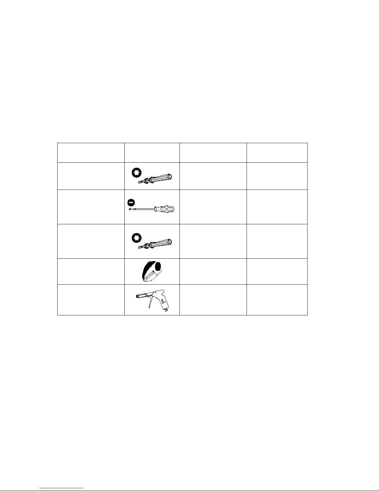
2 Tools
Before starting the installation the following tools should be at hand:
Table 1 Tools and Recommended Torque
Item Shape Used for Recommended
Torque
1.
Torque-driver
with TORX T08
bit
Power and
subscriber
connectors screws
0.3 Nm
2. Small flat head
screw driver
Opening cover for
and setting the DIP
switch of the
ESN212
-
3. Torque-driver
with TORX T30
bit
Screws (M6x16 mm)
for fastening units
and subracks to the
cabinet
10 Nm
4. Side-cutting
pliers
Cutting cable ties
-
5. Band tensioner
Tensioning cable ties
-
Apart from the tools some cable ties for fastening of the cables are needed.
The cable ties are not delivered with the equipment.
Page 8

Overview of the EDN612, ESN212, EPN210
4
3/1531-HSD 101 41 Uen E 2007-08-13
3 Overview of the EDN612, ESN212,
EPN210
The subrack is available in various configurations that can be adapted to
specific solutions.
The 19” subrack and the ETSI (21”) subrack can both be equipped with up
to 96 End-user lines. The subracks have a built-in cable tray and air guide
and it is possible to mount EDN612 IP DSLAMs, ESN212 switches,
external splitters, and an optional EPN210 Power Distribution Node in
different combinations. Table 2 and Table 3 on page 4 show examples on
various configurations.
Table 2 Examples of Possible Configurations in an ETSI Subrack
Number of
lines
Splitter EDN612 ESN212 EPN210
96 0 8 1 1
96 0 8 1 0
72 6 6 1 0
60 5 5 1 1
Table 3 Examples of Possible Configurations in a 19” Subrack
Number of
lines
Splitter EDN612 ESN212 EPN210
96 0 8 1 0
84 0 7 1 1
60 5 5 1 0
48 4 4 1 1
Page 9
Overview of the EDN612, ESN212, EPN210
3/1531-HSD 101 41 Uen E 2007-08-13
5
Table 4 on page 5 shows the dimensions for the nodes in the subrack
solutions.
Table 4 Size Dimensions for Subrack Solutions
Nodes Size
ETSI (inside) 481 mm
19” (inside) 431 mm
EDN612, ESN212 or EPN210 47 mm
Splitter 23 mm
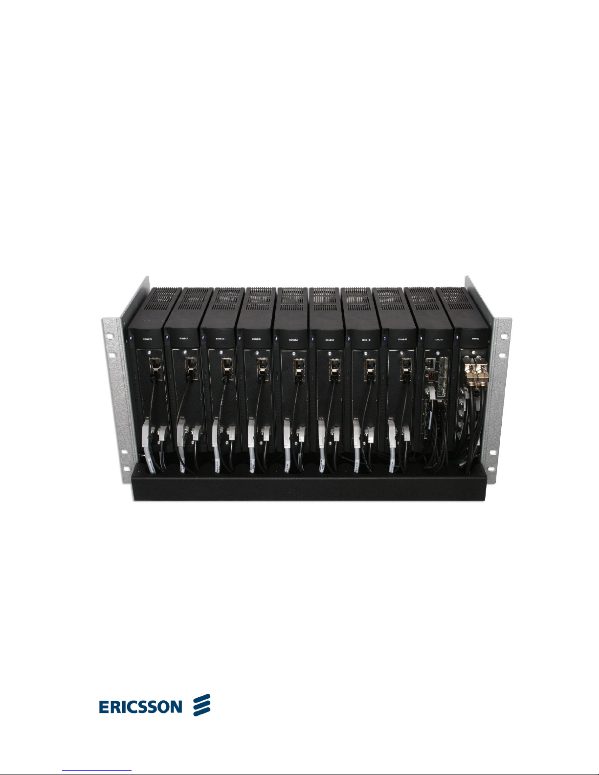
Figure 1 on page 5 shows a fully equipped 96-line ETSI subrack solution
without splitters with eight EDN612 IP DSLAMs, one ESN212 switch, and
one EPN210 Power Distribution Node.
Figure 1 96-line ETSI Subrack with EDN612, ESN212 and EPN210
Page 10

Overview of the EDN612, ESN212, EPN210
6
3/1531-HSD 101 41 Uen E 2007-08-13
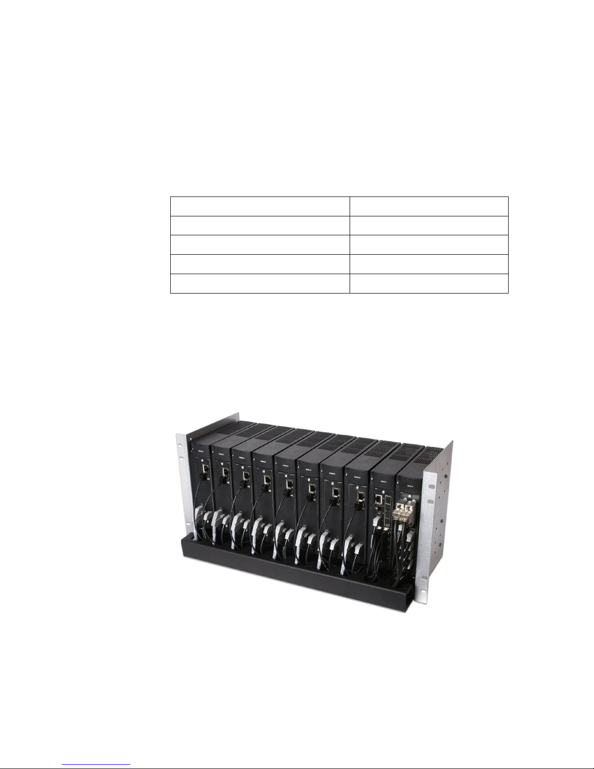
Figure 2 60-line ETSI Subrack with EDN612, ESN212, EPN210 and
Splitters
Page 11

Power Requirements and Distribution
3/1531-HSD 101 41 Uen E 2007-08-13
7
4 Power Requirements and Distribution
EDN612 and ESN212 use -48 volt power supply. Either High Ohmic
distribution system, or independent power distribution (Standard -48V
telecom supply) according to ETSI EN 300 132-2 v2.1.2 (2003 09) can be
used. 15A fuse is required. It is recommended to use EPN210 for the
power distribution as illustrated in the following figure:
Figure 3 Recommended Power Distribution
If another power distribution unit is used instead of the EPN210, it is
possible to use the TSR 263 65/xxx cables (EDA Power Cable Open End).
A solution to omit the EPN210, and use the 5:1 power distribution cable as
illustrated in the following figure:
Figure 4 Power Distribution
Note: The fuse is not part of any cable, and is purchased separately.
-48 VDC
Fuse
10 – 15A
EDN612
EDN612
ESN212
Cable: TSR 263 72/xxx
(EDA Power cable 5:1 open ended)
-48 VDC
Fuse
15A
EDN612
EDN612
ESN212
Cable: TSR 263 69/3000
(EDA D-Sub Power cable open
ended
)
Cable: TSR 263 70/600
(EDA Power cable standard)
EPN210
Page 12

Power Requirements and Distribution
8
3/1531-HSD 101 41 Uen E 2007-08-13
Open ended cables use the following coloring scheme:
Gray: 0 V (the 0 V is connected internally to the chassis in all devices)
Black: -48 V
When using EPN210 to distribute power to EDN312x it is recommended to
use the following configuration:
Figure 5 EPN210 Distributing Power to EDN312x
Note that when EDN312x is powered from an EPN210, there can be no
traffic uplink redundancy.
-48 VDC
Fuse
15A
EDN312x
EDN312x
Cable: TSR 263 69/xxx
(EDA D-Sub Power cable open
ended
)
Cable: TSR 263 71/xxx
(EDA Power cable RJ-45)
EPN210
Page 13

Environmental and Space Requirements
3/1531-HSD 101 41 Uen E 2007-08-13
9
5 Environmental and Space Requirements
The nodes complies with the following standards regarding storage,
transportation and operation. The operation category is also designated
stationary in-use at weather-protected locations.
• ETS 300 019-1-1: Storage, class 1.2
• ETS 300 019-1-2: Transportation, class 2.3
• ETS 300 019-1-3: Operation, class 3.3
• GR-3108-CORE class 3 operational temperature range (-40°C to 75°C)
The storage class 1.2 means tested for storage in weather-protected area,
not temperature-controlled.
The transportation class 2.3 means tested for public transportation.
The operation class 3.3 means tested for not partly temperature-controlled
location.
Caution!
The temperature within a rack assembly may be higher than the ambient
room temperature. Check that the rack environment temperature is within
the specified operating temperature range.
The nodes can be mounted in Ericsson subracks prepared for installation in
a 19” or ETSI rack. For detailed information, please see the Subracks
Installation Guide and Micro Outdoor Cabinet Installation Guide.
Mounting in the rack must be done in such a way that there is sufficient
space to allow airflow around the node as shown in Figure 6 on page 10.
Page 14

Environmental and Space Requirements
10
3/1531-HSD 101 41 Uen E 2007-08-13
Min.
50 mm
Min.
50 mm
Min.
70 mm
Mounting
rods
Min.
80 mm
Min. 300 mm
Min. 285 mm
(though only 250 mm
if installed in an EDA
1200 subrack with
Airguides)
Figure 6 Space Requirements when Mounting a Node
When the nodes are installed in the EDA subracks with air guides, the
subracks are mounted directly on to of one another. The following
requirements apply when using the EDA 1200 subracks:
Subrack
235 mm
15 mm
50 mm
Air guide
60 mm
Mounting
flange
Figure 7 Subrack Space Requirements
Page 15

Installation
3/1531-HSD 101 41 Uen E 2007-08-13
11
6 Installation
6.1 Preparation for Installation
The subrack is delivered in a cardboard box including assembly
instructions.
In Figure 8 on page 11 the assembled empty subrack is shown.
Figure 8 Assembled ETSI subrack
6.2 Mounting the EDN612, ESN212 and EPN210
Nodes
The EDN612, ESN212 and EPN210 nodes are mounted in the subrack
according to Figure 9 on page 12. The nodes can be mounted in different
ways see tables in section 3 on page 4.
Page 16

Installation
12
3/1531-HSD 101 41 Uen E 2007-08-13
Figure 9 Example of a mounted Subrack
6.2.1 Setting the Switch ID in ESN212
When the ESN212 SID value is different than zero, the Node controller in
the ECN will consider the ESN212 and the underlying nodes as a flexible
block with the SID value of the DIP switch. Note that value 255 is reserved
and cannot be used.
The Switch is located at the top of the ESN212, under the Fan assembly.
The DIP switch has eight on-off switches by which a binary value (0 – 255,
though 255 is reserved) is set.
Setting a switch to on, sets a bit to one, setting it to off, sets the bit to zero.
The following table shows some examples of switch settings and the
resulting SIDs:
EDN612 ESN212 EPN210
1
Ethernet connection
2
Power connection
3
Subscriber connection
4
External power connection
Page 17

Installation
3/1531-HSD 101 41 Uen E 2007-08-13
13
Table 5 SID Examples
DIP Switch Setting SID value
0
1
2
10
To set the SID do the following:
1. Remove the front cover of the fan assembly by inserting a flat
screwdriver in the bottom left side, turning it to open the cover and pool
the cover.
2. Insert a finger into the hole in the front and pull the fan assembly out.
1 2 3 4 5 6 7 8ON
1 2 3 4 5 6 7 8ON
1 2 3 4 5 6 7 8ON
1 2
1 2 3 4 5 6 7 8ON
Page 18

Installation
14
3/1531-HSD 101 41 Uen E 2007-08-13
3. Take out the rubber cover with a flat screwdriver
4. Set the DIP switch to the desired position
5. Put the rubber cover back in place
6. Press the fan unit into the cover. Do not press on the fan rotor or
motor. Slide the fan assembly onto the node, while holding the fan unit
pressed in the cover. Press until the fan assembly front is aligned with
the front of the node.
Page 19

Installation
3/1531-HSD 101 41 Uen E 2007-08-13
15
7. Mount the front cover back in place, sliding the right side in first and
then pressing the left side of the front cover.
6.2.2 Mounting the Hardware
All nodes are mounted on the rods in the same way. Insert the node on the
top rod first and than the bottom. Push the node firmly onto both rods.
6.2.3 Cabling of Ethernet Connections (No.1)
The EDN612 IP DSLAM is connected to the network (ESN212 switch)
using TSR 432 120/700 cable (1000 Base-T Patch cable STP).
In Figure 9 on page 12 (No. 1) shows Ethernet connections between the
EDN612 Uplink ports and the ESN212 downlink ports.
1
2
Page 20

Installation
16
3/1531-HSD 101 41 Uen E 2007-08-13
6.2.4 Cabling the Power Connections (No.2 and No.4)
The EDN612 IP DSLAM and ESN212 switch are connected to the EPN210
Power Distribution using TSR 263 70/600 cable (EDA Power cable
standard).
The cable connectors are fastened to the nodes by using a Torque-driver
with TORX T08 bit (0.3 Nm recommended). Figure 9 on page 12 (No. 2)
shows power connections.
The EPN210 Power Distribution Node is connected to an external power
distribution using TSR 263 69/3000 (EDA D-Sub Power cable open ended)
see details about the power requirements and distribution in section 4 on
page 7. Figure 9 on page 12 (No. 4) shows the external power distribution
connectors.
6.2.5 Cabling the Subscriber Line (No.3)
The EDN612 IP DSLAM is connected to the splitter using EDA Subscriber
cable. The subscriber cable is produced in different lengths. The following
cables are available:
Table 6
Ericsson no. Description
TSR 432 126/3000 EDA Subscriber cable open ended
3m
TSR 432 126/10M EDA Subscriber cable open ended
10m
TSR 432 138/500 EDA Subscriber cable Edge
connector 500mm
TSR 432 138/800 EDA Subscriber cable Edge
connector 800mm
To connect the subscriber lines cable align the cable connector with the
connector on the EDN612, and insert the connector gently.
!
Page 21

Installation
3/1531-HSD 101 41 Uen E 2007-08-13
17
Fasten the connector to the EDN612 using a Torque-driver with TORX T08
bit (0.3 Nm torque recommended). Figure 9 on page 12 (No. 3) shows the
subscriber cable connectors.
Figure 10 on page 17 shows the splitter connections.
Figure 10 Edge Connector with Splitter Connections
If it is desired to make a cable instead of using the standard cable it is
possible to do so using TFL 301 5202/12 cable and RNV 247 096/1
connector (subscriber connector). Use the EDA Subscriber hand tool (LSY
901 54) to connect the cable to the connector.
Figure 11 on page 18 shows the subscriber cable (color code according to
IEC 189-2) between the EDN612 and the splitter.
Connection to EDN612
Connection to Exchange Connection to Line
Page 22

Installation
18
3/1531-HSD 101 41 Uen E 2007-08-13
Figure 11 Subscriber Cable
6.2.6 SFP Cages for ESN212
The SFP cages enable the use of different SFP modules for the ESN212
switch depending of the use. These ports may be used as uplinks or as
downlinks. The following modules are available:
Table 7
Module Ericsson no. Description
SFP SX 500M ROA 128 0839/1
Short-wavelength SFP transceiver with max
500 m reach
SFP LX 10KM ROA 128 0839/2
Long-Wavelength SFP Transceiver for reach
up to 10 km
SFP LX 35KM ROA 128 0839/3
2 Gigabit Long-Wavelength SFP Transceiver
with max 35 km reach
Page 23

Installation
3/1531-HSD 101 41 Uen E 2007-08-13
19
Module Ericsson no. Description
SFP LX 80KM ROA 128 0839/4
2 Gigabit Long-Wavelength SFP Transceiver
with max 80 km reach
SFP FCLF8520/8521-3
RYT 921 605/1
10/100/1000 BASE-T Electrical SFP
transceiver
Note: The above mentioned SFP modules may have a different operating
temperature range than the ESN212.
6.3 Mounting the Front Cover for the Cable Tray
After all cables have been mounted the front cover for the cable tray has to
be mounted according to Figure 12 on page 19.
Figure 12 Mounting the Front Cover
Page 24

Initial Configuration and Commissioning
20
3/1531-HSD 101 41 Uen E 2007-08-13
7 Initial Configuration and Commissioning
7.1 Embedded Nodes
It is not needed to do any configuration for either ESN212 or EDN612. The
default settings for the ESN212 switch are following:
• IGMP Snooping Enabled
• DHCP Interception Enabled
• Management VLAN 247
• Untagged Management VLAN 1
• RSTP and MSTP Disabled
7.2 Stand Alone ESN212
When the ESN212 is not embedded it must be configured for static IP and
for the management VLAN. To make the initial configuration a terminal (or
a PC with a terminal emulation application such as HyperTerminal) and a
consol connection cable are needed. The consol cable is not delivered with
the ESN212.
Consol Connection Cable
Use a standard straight through LAN cable with a standard converter, or
make a cable with the following connections:
Page 25

Initial Configuration and Commissioning
3/1531-HSD 101 41 Uen E 2007-08-13
21
Figure 13 RJ-45 and D-SUB 9 Pin Numbering
Table 8 Console Cable RJ-45 to D-SUB 9 Pin Assignment
RJ-45 Pin Signal Name D-SUB 9
1 Not used -
2 Not used -
3 Not used -
4 ------- Ground ---------- 5
5 RXD -----<-------- TXD 3
6 TXD ------->------ RXD 2
7 Not used -
8 Not used -
1. Connect the cable to the Console terminal
2. Set the following setting in the terminal emulation application:
• Data rate to 9600 baud.
• Data format to 8 data bits, 1 stop bit, and no parity.
• Flow control to none, emulation mode to VT100
3. Logon to the ESN212 with the username admin and password admin.
4. Set the management VLAN to the VLAN used in the network (if this
VLAN is different from 247. For example 246:
5
1
6
9
RJ45
1
8
D-SUB 9 female
Page 26

Installing and Upgrading the Software
22
3/1531-HSD 101 41 Uen E 2007-08-13
ESN212# management vlan 246
5. Configure IP parameters. In the following example the following
parameters are set:
− IP address 172.30.10.100
− Subnet mask 255.255.255.0
− Trap receiver 172.30.10.10
− SNTP server 172.30.10.10
− Default gateway 172.30.10.1
Note that Trap receiver, SNTP server and default gateway must be
configured even though they might be overwritten by a management
system (PEM for example).
esn212# boot mode manual ip address 12.30.10.100
255.255.255.0 trap receiver 12.30.10.10 sntp server
12.30.10.10 def gateway 12.30.10.1
6. Restart the ESN212:
esn212# restart
Note that the settings are automatically saved. It is therefore not necessary
to save them manually before the restart.
8 Installing and Upgrading the Software
Both application and boot SW of the ESN212 and EDN612 is upgraded
from the ECN330 Ethernet Controller Node (CLI) or from a management
system. See the management system documentation or the ECN330 User
Guide for instructions.
Page 27

Verification of the Installation
3/1531-HSD 101 41 Uen E 2007-08-13
23
9 Verification of the Installation
Verification of the installation is done through the Ethernet Controller Node.
See the ECN330 Installation Guide for instructions.
Page 28

Ericsson AB
© Ericsson AB 2006-2007. All Rights Reserved
www.ericsson.com 3/1531-HSD 101 41 Uen E 2007-08-13
 Loading...