

Page 1

Accessories
Ericsson Mobile Phone EF738
Page 2

Accessories
2
Page 3

Accessories
Contents
Rapid Charger _____________________________________ 7
Introduction ______________________________________________ 7
Main Features ____________________________________________ 7
Versions ____________________________________________________ 8
Connectors _______________________________________________ 8
Secondary DC-cord ___________________________________________ 8
Specifications _____________________________________________ 8
Travel Charger ___________________________________ 9
Introduction ______________________________________________ 9
Main Features ____________________________________________ 9
Indicators __________________________________________________ 10
Output Characteristics ____________________________________ 10
Connector_______________________________________________ 11
Secondary DC-cord __________________________________________ 11
Specifications ____________________________________________ 11
Vehicle Power/Charger _____________________________ 13
Introduction _____________________________________________ 13
Main Features ___________________________________________ 13
Indicators __________________________________________________ 14
Output Characteristics ____________________________________ 14
Connectors ______________________________________________ 15
Cigarette Lighter Adaptor______________________________________ 15
Power Plug _________________________________________________ 15
Specifications ____________________________________________ 15
Continued on next page
3
Page 4

Accessories
DeskTop Charger MC7000 __________________________ 17
Introduction______________________________________________17
Electronics _______________________________________________18
Central Processing Unit _______________________________________ 18
Supply Current Monitor _______________________________________ 19
Charge Switches ______________________________________ ____ ___ 19
Front Slot Switch__________________________________________ 19
Rear Slot Switch __________________________________________ 19
Voltage Monitors ____________________________________________ 19
Front Slot Monitor_________________________________________ 19
Rear Slot Monitor _________________________________________ 19
Phone On/Off Status__________________________________________ 20
Discharger__________________________________________________ 20
LED Indicators ______________________________________________ 20
Front LEDs ______________________________________________ 20
Rear LEDs _______________________________________________ 20
Temperature Guard___________________________________________ 20
Power Distribution for Phone Operation ______________________20
Battery Charging _________________________________________20
Front Slot Charger____________________________________________ 21
Main Charging____________________________________________ 21
Trickle Charging __________________________________________ 21
Rear Slot Charger ____________________________________________ 21
Main Charging____________________________________________ 21
Trickle Charging __________________________________________ 21
Discharging ______________________________________________ 21
Error Detection ______________________________________________ 22
LED Indicators ______________________________________________ 22
Front Indicator - Phone Slot__________________________________ 22
Rear Indicator - Spare Battery Slot ____________________________ 22
Specifications_____________________________________________22
Connectors and Signals ____________________________________23
System Bus Connector ________________________________________ 23
Front Slot ___________________________________________ ____ ___ 23
Rear Slot ___________________________________________________ 24
Portable HandsFree ____ ____ ___ ___ ____ ___ ___ ____ ___ _ 25
Introduction______________________________________________25
Portable HandsFree Features _______________________________25
Specifications_____________________________________________26
Microphone_________________________________________________ 26
Earphone___________________________________________________ 26
Connector and Signals _____________________________________26
Continued on next page
4
Page 5

Accessories
Vehicle HandsFree Solution HF7300 __________________ 27
Introduction _____________________________________________ 27
HandsFree Features ______________________________________ 27
HandsFree Components ___________________________________ 28
Cradle _____________________________________________________ 28
Stick-On Microphone_________________________________________ 28
External Speaker_____________________________________ _____ ___ 28
HandsFree Unit______________________________________________ 28
Microphone Amplifier______________________________________ 29
Speaker Amplifier _________________________________________ 29
Modem/Handset Option ____________________________________ 29
Audio Switch Control ______________________________________ 29
External Audio Control_____________________________________ 29
Music Mute Control _______________________________________ 29
Power Supply_____________________________________________ 30
Optional Accessories ______________________________________ 30
Music Mute_________________________________________________ 30
Goose-Neck Microphone ______________________________________ 30
Data Extension ______________________________________________ 30
External Handset_______________ ____ __________________________ 30
Specifications ____________________________________________ 31
HandsFree Unit______________________________________________ 31
Cradle _____________________________________________________ 31
Connectors and Signals____________________________________ 32
Holder_____________________________________________________ 32
System Connector _________________________________________ 32
HandsFree Unit______________________________________________ 32
System Connector J1_______________________________________ 33
Power Connector J2________________________________________ 33
Microphone Connector J4___________________________________ 34
Music Mute Connector J5___________________________________ 34
Data Communication Connector J6____________________________ 34
Speaker Connector J7 ______________________________________ 34
Continued on next page
5
Page 6

Accessories
Vehicle HandsFree Solution HF7600 __________________ 35
Introduction______________________________________________35
HandsFree Features _______________________________________35
Echo Cancellation____________________________________________ 36
Noise Reduction _____________________________________________ 36
HandsFree Components____________________________________36
Cradle _____________________________________________________ 36
Stick-On Microphone _________________________________________ 36
External Speaker_____________________________________________ 37
Handsfree Unit ______________________________________________ 37
Digital Signal Processor (DSP) _______________________________ 37
Audio-To-Mobile-Station ___________________________________ 37
Audio-From-Mobile-Station _________________________________ 37
Microphone Amplifier______________________________________ 37
Speaker Amplifier _________________________________________ 37
Music Mute Control________________________________________ 38
Power Supply_____________________________________________ 38
Optional Accessories_______________________________________38
Music Mute_________________________________________________ 38
Goose-Neck Microphone ______________________________________ 38
Data Extension ______________________________________________ 38
External Handset _____________________________________________ 39
Specification______________________________________________39
Handsfree Unit ______________________________________________ 39
Cradle _____________________________________________________ 39
Connectors and Signals ____________________________________40
Holder _____________________________________________________ 40
System Connector _________________________________________ 40
HandsFree Unit______________________________________________ 40
System Connector J1_______________________________________ 41
Power Connector J2________________________________________ 41
Microphone Connector J4 ___________________________________ 42
Music Mute Connector J5 ___________________________________ 42
Data Communication Connector J6____________________________ 42
Speaker Connector J7 ______________________________________ 42
6
Page 7

Rapid Charger
Introduction
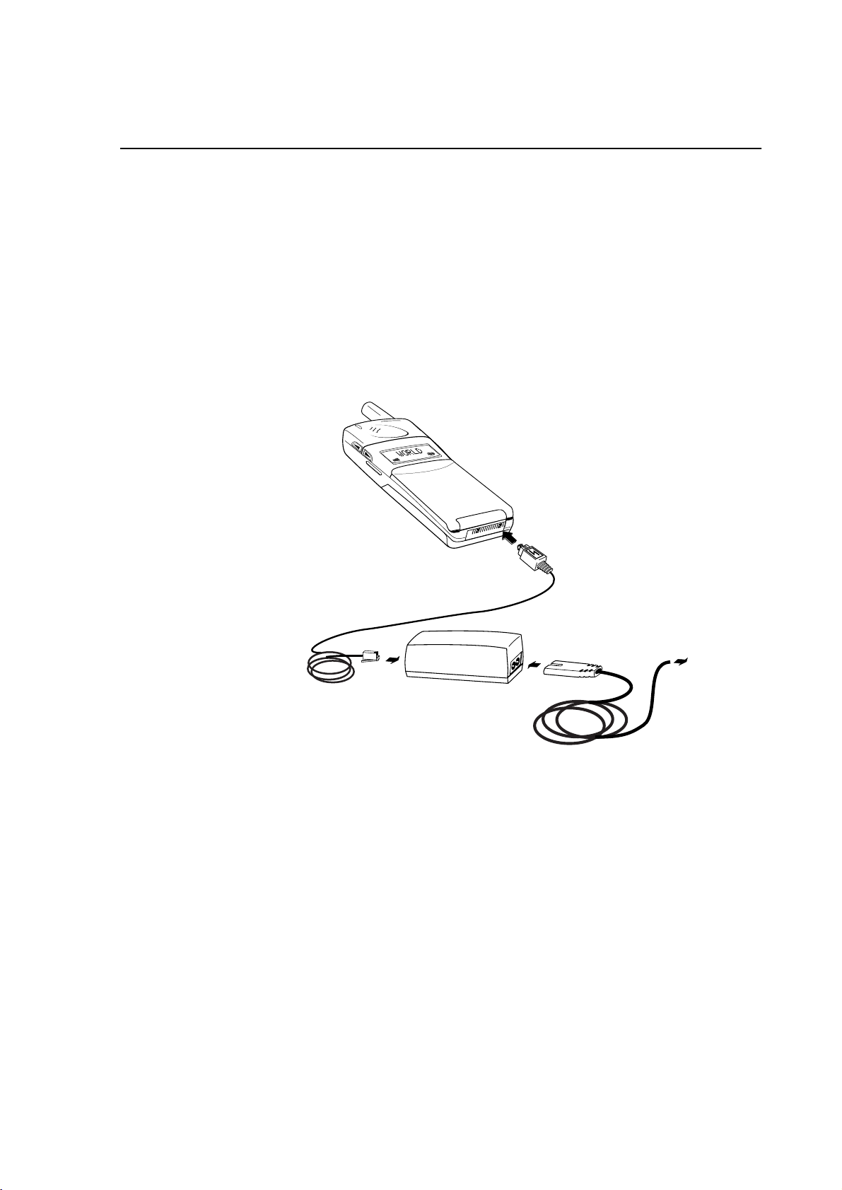
Rapid Charger
The
tional transformer followed by a rectifying circuitry. This charger can consequently
not be used worldwide, as opposed to a primary switched charger, and will therefor
be available in several different versions as listed on next page.
Rapid Charger
The
•
AC/DC converter incl. wall plug
•
secondary cord with power connector
Accessories
is a basic charger which converts AC to DC by using a conven-
consists of:
The AC/DC converter is plugged directly into the mains power outlet and the rectified DC voltage/current is distributed via the secondary cord to the power connector, which is plugged into the system connector of the phone.
Main Features
Rapid Charger
The
•
•
7X8
the
the DeskTop Charger MC7000
-family phones
can be used as power source in two different ways, for:
7
Page 8

Accessories
Versions
Rapid Charger
The
quencies, and power outlets as specified below:
Mains voltage Frequency Mains plug
115V ±10% 60Hz ±5% US standard
230V -10% to +6% 50Hz ±5% EU standard
240V -10% to +6% 50Hz ±5% UK standard
240V ±10% 50Hz ±5% AUS standard
is designed in several vers ions for different mains voltages, fre-
US (Thailand)
UK (Hong Kong)
Connectors
Secondary DC-cord
GND
V
DC
Specifications
Type No: 402 0034-UK
Dimensions:
- AC/DC-Converter 78 x 42 x 45 mm; 3.1 x 1.7 x 1.8 in (excl. wall plug)
- Power Plug 24 x 11 x 11 mm; 0.9 x 0.4 x 0.4 in
/700mA
DC
Versions
Versions
above
above
Input Voltage Refer to
Input Frequency: Refer to
Output Voltage/Current: 6V
8
Page 9
Travel Charger
Introduction
Travel Charger
The
and power supply world wide without the need of an AC/AC-converter.
Travel Charger
The
•
mains primary AC-cord
•
AC/DC-converter
•
secondary DC-cord
Accessories
is a primary switched AC/DC-converter to be used as charger
consists of three parts:
Main Features
Travel Charger
The
•
•
7X8
the
the DeskTop Charger MC7000
-family phones
can be used as power source in two different ways, for:
9
Page 10

Accessories
Indicators
A green LED located next to the secondary DC output is turned on whenever the
mains voltage is available on the primary side
LED
V
DC
output
connector
Output Characteristics
The output voltage and current of the
within the values indicated as “white” area in the picture below.
U (V)
8.4
7.6
2.0
Output power characteristics within range
Travel Charger
600 900
should after 5 minutes stay
1000
I (mA)
10
Output power characteristics within range first 5 minutes
Output power characteristics out of range after 5 minutes
Output power characteristics out of range
Page 11

Connector
Secondary DC-cord
GND
n.c.
V
DC
n.c.
GND
V
DC
Accessories
Specifications
Type No: 402 0036-BV
Dimensions:
- AC/DC-Converter 95 x 38 x 27 mm; 3.7 x 1.5 x 1.1 in
- Power Plug 24 x 11 x 11 mm; 0.9 x 0.4 x 0.4 in
Input Voltage 100 - 240 V
Input Current: 150mA (typical)
Input Frequency: 50 - 60 Hz (±5%)
Output Voltage/Current: 7.6 V
/600mA
DC
AC
(±10%)
11
Page 12

Accessories
12
Page 13

Vehicle Power/Charger
Introduction
Vehicle Power/Charger
The
and power supply for the phone when plugged into the +12V or + 24V (negative
ground) cigarette lighter outlet.
Vehicle Power/Charger
The
•
cigarette lighter adaptor
•
coiled cord
•
power plug
is an integrated unit consisting of three parts:
Accessories
is a step-down DC/DC-converter to be used as charger
Main Features
Vehicle Power/Charger
The
•
•
7X8
the
the DeskTop Charger MC7000
-family phones
can be used as power source in two different ways, for:
13
Page 14

Accessories
Indicators
A green LED located next to the coi led cord out let of th e cigare tt e light er adapt or is
turned on whenever the appropriate vehicle voltage is available.
LED
Output Characteristics
The output voltage and curr ent of the
Vehicle Power and Charger
the values indicated as “white” area in the picture below.
U (V)
8.4
7.6
600 900
Output power characteristics within range
should stay wit hin
I (mA)
14
Output power characteristics out of range
Page 15

Connectors
Cigarette Lighter Adaptor
Ground Spring+V
Power Plug
Accessories
GND
V
DC
Specifications
Type No: 402 0035
Dimensions:
- Cigarette Lighter Adaptor 96 x 28 x 25 mm; 3.8 x 1.1 x 1.0 in
- Power Plug 24 x 11 x 11 mm; 0.9 x 0.4 x 0.4 in
Input Voltage 10.8 - 31.2 V
Output Voltage/Current: 7.6VDC/600mA
DC
15
Page 16

Accessories
16
Page 17

DeskTop Charger MC7000
Introduction
DeskTop Charger MC7000
The
7X8
-family telephones. The phone is placed in the front slot for simultaneous powering and battery ch argi ng, whil e the spar e battery to be char ged is p laced i n the rear
slot, which also features a manual discharge/reconditioning facility.
is a dual desk charger specially designed for the
Accessories
As the
has to be connected to the system bus connector at the rear of the unit.
The external power source should be one of the following Ericsson product:
•
•
•
Furthermore, the Portable HandsFree as well as Mobile Office equipment can be
connected to the
MC7000
Rapid Charger
Travel Charger
Vehicle Power/Charger
does not
DeskTop Charger MC7000
include an intern al power s upply, an external power source
.
17
Page 18

Accessories
Electronics
The electronics of the
MC7000
is designed around the Central Processing Unit.
Central Processing Unit
The Central Processing Unit (CPU) is equipped with 4kbyte ROM, thus making it
possible to control the entire
The supply voltage to the CPU is +3.8V which is being derived from a linear voltage regulator and a cryst al gene ra tes a 5MHz clock fre quency to the oscil lato r in put
of the CPU.
The Central Processing Unit interacts with the following major peripheral blocks:
•
Supply Current Monitor
•
Charge Switches; front & rear
•
Voltage Monitors; front & rear
•
Phone On/Off Status
•
Discharger
•
LED Indicators; front & rear
•
Temperature Guard
System
Bus
Connector
ACCDCIO
Supply
Current
Monitor
MC7000
charger.
Front
Charge
Switch
Rear
Charge
Switch
Front
Voltage
Monitor
Front
Slot
DCIO
VDD
Rear
Slot
+V
18
Temp
Guard
Front
LEDs
Rear
LEDs
Rear
Voltage
Monitor
CPU
Phone
On/Off
Status
Dis-
charger
Page 19

Accessories
Supply Current Monitor
The current distributed from the external power source to the front or rear slot
passes through the Supply Current Monitor. The CPU reads the output from the
Supply Current Monitor is order to establish whether
pleted
is in effect as follows:
>200mA: Charging
<200mA: Charging completed
charging
charging com-
or
Charge Switches
The current from the external power source to the two slots can independently be
switched On/Off by two separate CPU outputs.
Front Slot Switch
This CPU controlled switch is normally On except when the spare battery is being
charged.
Rear Slot Switch
The rear slot charging switch is controlled by the second CPU output, which will
allow charging of t he spar e batt ery onl y if the phon e batte ry is f ully c har ge d or if no
phone is inserted in th e fr ont slot. This switch goes Off for a short while once every
other second for voltage reading purposes.
Voltage Monitors
The CPU controls the Voltage Monitors to enable reading of the battery voltages.
Front Slot Monitor
If the CPU input of the Front Slot Voltage Monitor suddenly detects a voltage at
DCIO when the corresponding charge switch is Off, this means that the voltage is
coming from the battery, i.e. a phone has been inserted into the slot. This will be
detected regardless of whether the phone is turned On or Off. If Off when inserted,
the auto-turn-on mode will turn it On.
However, if th e phone is removed during charging, e.g. when a call is rec ei ved, this
will not be detected as this input still will read a voltage, now coming from the
external power source. (See Phone On/Off Status on next page)
Rear Slot Monitor
The Rear Slot Voltage Monitor detects whether the spare battery requires charging.
During the charging the current is switched off for a short while every other second
in order to read the battery voltage and in this way establish whether the battery is
fully charge d or not. The CPU is i n t his way also informe d i f t he battery is rem oved
during the charging process.
19
Page 20

Accessories
Phone On/Off Status
The VDD input indicates wheth er the phone is Off or On and will inf orm the CPU if
the phone has been removed during charging.
Discharger
To prolong the battery life the rear slot is equipped with a reconditioning feature.
By pressing the discharge switch (same as the rear LED indicator), the CPU
becomes notified th at it will have to car ry out a dischar ge oper ation on th e batte ry in
the rear slot.
The CPU then activates the dis cha rge operation by draini ng t he bat t ery at a suitable
resistive load.
LED Indicators
The LEDs are used for indication of the various charging phases.
Front LEDs
The two front LEDs (green and red) can be On and Off in any combination except
both On.
Rear LEDs
The two rear LEDs (green and red) can be On and Off in any combination.
Temperature Guard
A temperature related voltage is generated due to an onboard NTC resistor and fed
to an input of the CPU for detection and measures to prevent overheating. The
threshold is set to +55°C onboard corresponding to an ambient temperature of
+35°C.
Power Distribution for Phone Operation
The power to the front slot for phone operation is entirely controlled by the phone.
The various current values needed in different situations, like stand-by or transmission, are programmed and stored in the telephone.
MC7000
The
source is being connected.
is able to deliver 500 - 700 mA to the phone depending on the power
20
Battery Charging
The charging of both batteries is turned on and off by a switch circuitry which is
controlled by the Centra l Processi ng Unit. Char ging is onl y possible f or one slot at a
time where the front slot has got highest priority, i.e. charging of the spare battery
will not begin until the phone battery is fully charged or removed.
The batteries being used are four 1.2V cell NiMH (Nickel-Metal-Hydride) or NiCd
(Nickel-Cadmium) chargeable batteries, without internal thermistor.
Page 21

Accessories
Front Slot Charger
Main Charging
The charging is entirely controlled by the phone, which after being inserted into the
charger slot starts being charged by the
battery in the rear slot is interrupted, and 500 - 700 mA is delivered to the phone
battery.
Note!
The phone does not have to be turned On when inserted into the charger slot
due to its auto-turn-on feature.
MC7000
. Any possible charging of a spare
Trickle Charging
After the main charging the phone automatically returns to normal power distribution and trickle charging unless a spare battery then is going to be charged. The
power distributi on and tr ickle cha rgi ng to the phone i s in tha t case i nhibite d until t he
spare battery charging is terminated.
Rear Slot Charger
Main Charging
The 500 - 700 mA charging current to the spar e bat ter y is ent ir el y cont ro lled by the
Central Processin g Unit. Sev eral algorit hms are use d to e stablis h when the battery is
fully charged:
•
-dv/dt
The battery voltage is sampled once a second for approximately one minute and
the mean value is calculated. The max. mean value is stored and compared with
consecutive values. When a specific divergence is obtained, the charging is terminated.
•
peak detect
The charging is t erminated when the above mentio ned values a re less or iden tical
to the max. mean value for a specific time.
•
safety time elapsed (4 hours)
The safety timer is used as a last resort wh en the above methods fail.
Trickle Charging
When the main charging is completed an 8mA trickle charging generated by short
pulses is automatically initiated, but only in case the front slot is empty.
Discharging
After pressing the discharge button the spare battery is discharged by a 200mA current. Charging will commence when the battery voltage has dropped to 4.0V.
21
Page 22

Accessories
Error Detection
An error is indicated and charging is halted for 20 minutes when the ambient temperature is higher than +35°C.
LED Indicators
Front Indicator - Phone Slot
Status Significance Detection
Off No phone Front Voltage Monitor or Phone On/Off Status
Red Charging Supply Current Monitor >200mA
Green Charging complete Supply Current Monitor <200mA
Rear Indicator - Spar e Battery Slot
Status Significanse Detection
Off No battery Rear Voltage Monitor
Red Charging Rear Voltage Monitor
Green Charging complete Rear Voltage Monitor
Yellow Discharging Discharge Switch
Red flash Temperature error Temperature Guard
Specifications
Battery type Charging time - Front Charging time - Rear
NiMH 650mAh:≈1h50min
Type No.: 402 0040-BV
402 0040-UK
Dimensions: 73 x 90 x 47 mm
2.9 x 3.5 x 1.9 in
Input voltage: 7 - 10 V
Ambient temp: +5°C to +35°C
+41°F to +95°F
DC
≈
1h25min
22
Page 23

Connectors and Signals
System Bus Connector
Accessories
1
23
11
12
Pin Signal Specification
1 AFMS Audio-from-mobile -station
2 ATMS Audio-to-mobile-station
3 EXTAUD External analog audio accessory sense
4 AGND Audio signal ground, 0V refernce
5 PORTHF Portable handsfree
6 MUTE Music mute
7 VPPFLASH Flash memory voltage and service voltage
8 VDD Logic reference, status On
9 DFMS Data from mobile station
10 DGND Digital ground and DC return
11 DTMS Data to mobile station
12
ACCDCIO
DCIO
1)
DC positive pole for phone battery charging and exter-
2)
nal accessory powering
1) System Bus Connector
2) Front Slot Connector
Front Slot
112
Note: For pin assignments, refer to
System Bus Connector
above
23
Page 24

Accessories
Rear Slot
- Negative pole
+ Positive po le
24
Page 25

Portable HandsFree
Introduction
Portable HandsFr ee
The
mobility of a handhe ld pho ne with t he ad vantag es of being handsf ree.Th e fol lowing
three main components are included:
•
microphone
•
earphone
•
connector
The connector is plugged into the system connector of the phone. After fitting the
earphone and attaching the microphone clip to a suitable part of the clothing, the
portable handsfree facility is ready to be used.
Accessories
is a light-weight un it which al lows the user to combi ne the
Portable HandsFree Features
Portable HandsFr e e
The
family.
The portable handsfree communi cation is full duplex, i.e. both par ties will be able to
talk simultaneously.
is designed to be used wit h all phon es i n the Eri csson
7X8
25
-
Page 26

Accessories
Specifications
Type No.: 502 0013-BV
Microphone
Characteristics: Omnidirectional
Sensitivity: -43.5dB ±3dB rel. 1V/Pa at 1kHz
≤
Impedance:
S/N ratio:
Earphone
Sensitivity: 106dB/250mV at 1kHz
Impedance: 16
2k
≥
35dB
Ω
Ω
Connector and Signals
PORTHF
GND
MIC
EAR
Portable HF connector Signal direction System connector
MIC ATMS
EAR AFMS
GND GND
26
PORTHF (actice LO) PORTHF (detect)
Page 27

Vehicle HandsFree Solution HF7300
Introduction
Accessories
Vehicle Handsfree Solution HF7300
The
family telephones and includes apart from the handsfree facilities also a power supply for battery charging and phone operation.
The four main components are:
•
Cradle
•
Stick-On Microphone
•
External Speaker
•
Handsfree Unit
is specially designed for the Ericsson
7X8
-
HandsFree Features
The HandsFree Unit does not include a DSP (digital signal processor) as the CPU
(Central Processing Unit) of the telephone handles the handsfree switching.
The handsfree function is semi-duplex, which only permits one party to talk at a
time while the other party is switched off to avoid feedback. When the land side
party is talking, a "comfort noise" is added to simulate the background noise heard
from the mobile .
27
Page 28

Accessories
HandsFree Components
Cradle
The cradle consists of tw o sub-units, the
Cradle Attachment
The Cradle is equipped with a slide joint which is adjusted during the installation to
a suitable vertical and horizontal angle for easy reach of the phone. The snap/clickin Holder connects the phone to the HandsFree Unit.
Cradle Attachment
and the
Holder.
Holder
Stick-On Microphone
The Stick-On Microphone included in the kit is a unidirectional microphone to be
mounted in a fixed position in the vehicle and connected to the HandsFree Unit.
External Speaker
Unless an optional Music Mute unit is utilised, the 4Ω External Speaker has to be
connected to the speaker amplifier output of the HandsFree Unit.
HandsFree Unit
The HandsFree Unit includes the following electronic blocks:
•
Microphone Amplifier
•
Speaker Amplifier
•
Modem/Handset Option
•
Audio Switch Control
•
External Audio Control
•
Music Mute Control
•
Power Supply
28
Page 29

Accessories
Microphone Amplifier
The Microphone Amplifier has got two in dividu al input s for the two types of mic rophones being available:
•
Stick-On microphone (standard)
•
Goose-Neck microphone (optional)
The microphone signal passes through two amplifier stages which results in a total
gain of 31dB and 21dB for the Stick-On and Goose-Neck microphone resp.
Speaker Amplifier
The AFMS (audio-from-mobile-st ation) signa l received from the phone is amplifi ed
by a programmable gain amplifier and fed to a differential amplifier consisting of
four power transi st ors resulting in a total gain of 21 dB. To protect the power tra nsi stors and the speaker against high current, a feed back signal from the power transistors to the programmable amp will allow only short peaks of high current to get
through but reduce continuous high current to approximately 1.2 A correspo nding to
just about 5W output power.
Modem/Handset Option
The Data Communication connector can be utilised for connection of two different
options:
•
analog PCMCIA modem
•
external handset
When any of these devices is connected the audio signal ATMS (Audio-To-MobileStation) is switched to this connector, while AFMS (audio-from-mobile-station)
always is available.
Note
: A Data Extension Unit is required for the connection between the optional
unit and the Data Communication connector.
Audio Switch Control
The Audio Multiplexer Control is used to switch the audio paths between the external microphone and the modem/handset connector.
Control signals such as EXTAUD (external audio control) and MUTEINV (in verted
mute) are derived from logical gates controlled by the signals PORTHF (portable
handsfree), DV (data/voice), and HOOKSNS (hook sense).
External Audio Control
The EXTAUD (external audio control) signal informs the phone when an accessory
which is using the two ext ernal a udio si gnals AFMS and ATMS has been connecte d
to the HandsFree Unit
Music Mute Control
An optional Music Mute unit can be supplied with +12V from the vehicle battery.
The Music Mute function is contr olled from the pho ne by the MUTE signal which i s
29
Page 30

Accessories
inverted by an open col lect or tra nsist or bef ore becoming a vai lable at two of the con nectors.
Power Supply
The Handsfree Unit is able to deliver power to the phone for operation and battery
charging by regulating the +12V of the vehicle battery to a constant current supply
of max. 850mA and less than 1mA during stand-by.
Phone Operation:
The power consumption of the phone in different situations, e.g. in stand-by or in
transmission, is ent irel y cont roll ed by t he phon e its elf, as the se powe r lev els ar e pro grammed and stored in the phone.
Battery Charger:
As the phone battery at all times is provided with current from the HandsFree Unit,
the charging of the battery, incl. trickle charging, is controlled by the phone itself.
For more information regarding the battery charging algorithms of the telephone,
refer to section 2,
Technical Description
, subsection
Battery Charging
.
Optional Accessories
Music Mute
An optional Music Mute unit can be connected to the HandsFree Unit and will
direct the amplified received audio signal to the car stereo speakers during the
handsfree conversation.
If the car stereo is equipped with a specific “mute” input, the optional Music Mute
Cable connected directly between this input and the HandsFree Unit will mute the
car stereo during the handsfree conversation.
Note:
Max. current load at Music Mute output is 200mA.
Goose-Neck Microphone
A Goose-Neck Microphone allows a more flexible microphone position for
improved sound quality incl. reduction of transmitted noise.
Data Extension
Data communication using handsfree mode is made possible by connecting a Data
Extension Unit between a modem and the Data Communication Connector.
30
External Handset
An External Handset will give the user the possibility to switch from handsfree to
handheld operation wit hout di sconnec ting t he power source . A Data Ext ensio n Unit
is required for the connection between the External Handset and the Data Communication Connector.
Page 31

Accessories
Specifications
HandsFree Unit
Type No: 502 0019-BV
Dimensions: 135 x 100 x 28 mm; 5.3 x 3.9 x 1.1 in
Input Voltage: 10.8 to 15.6 VDC
Ambient Temperature - Operating:
Ambient Temperature - Charging:
Cradle
Weight: 105g; 3.7 oz
Height: 95mm; 3.7 in
Depth (incl. cradle attachment): 54mm; 2.1 in
o
-25
C to +60oC; -13oF to +140oF
o
+10
C to +35oC; +50oF to +95oF
Width: 60mm; 2.4 in
31
Page 32

Accessories
Connectors and Signals
Holder
System Connector
112
Note
: For pin assignments, refe r to column
next page.
HandsFree Unit
J4 J7 J6
J5
J1 J2
H-pin
of System Connector J1 table on
32
Page 33

System Connector J1
Accessories
12
11
J1-pin H-pin Signal Specification
1 10 DGND Digital ground & DC return
2 12 DCIO DC voltage supply to phone power
3 4 AGND Audio signal ground & 0V reference
4 2 ATMS Audio to mobile station
5 - HOOKSNS Hook sense (connected to cradle, not phone)
6 1 AFMS Audio from m obile station
7 6 MUTE Music Mute
8 3 EXTAUD External analog audio accessory sense
9 5 PORTHF Portable handsfree sense
10 8 VDD Logic reference, status ON
2
1
11 9 DFMS Data from mobile station
12 11 DTMS Data to mobile station
J1-pin = HandsFree Unit System Connector J1 pin
H-pin = Holder System Connector pin
Power Connector J2
3
4
1
2
1 GND
2+12VDC
3 M UTEINV
4n.c.
33
Page 34

Accessories
Microphone Connector J4
1 +10dB Stick-On microphone
2 0dB Goose-Neck microphone
3 AGND Signal ground
Microphone connector J4 is female
Picture shows corresponding male
Music Mute Connector J5
1 LSP- Loudspeaker common
2 DGN D Digital ground & DC return
3 LSP+ Loudspeaker signal
4 MUTE Music mute
5 DC12OUT +12VDC output
Music Mute connector J5 is male
Picture shows corresponding female
Data Communication Connector J6
1 MUTEINV Music Mute (inverted)
2 VDD Logic reference, status ON
3 DC12OUT +12VDC output
4 AFMS (RX) Audio from mobile station
5 D/V Data/voice signal
6 ATMS (TX) Audio to mobile station
7 PORTHF Portable handsfree sense
8 DTMS Data to mobile station
9 DFMS Data from mobile station
10 DGND Digital ground & DC return
Speaker Connector J7
34
1 LSP+ Loudspeaker signal
2 LSP- Loudspeaker common
3n.c.
Speaker connector J7 is female
Picture shows corresponding male
Page 35

Vehicle HandsFree Solution HF7600
Introduction
Accessories
Vehicle Handsfree Solution HF7600
The
family telephones and includes apart from the handsfree facilities also a power supply and battery charger for the phone.
The four main components are:
•
Cradle
•
Stick-on Microphone
•
External Speaker
•
HandsFree Unit
is specially designed for the Ericsson
7X8
-
HandsFree Features
After placing the telephone in the
trolled by the DSP (Digital Signal Processor) and its peripherals located in the
HandsFree Unit.
The handsfree communication is full duplex, i.e. both parties will be able to talk
simultaneously. Some attentuation can however be noticed on the land side during
simultaneous talking, whil e both speech chann els will be open on the mobil e side all
the time.
HF7600
holder, all handsfree functions are con-
35
Page 36

Accessories
Echo Cancellation
To avoid acoustic feedback in a full duplex handsfree system, i.e. prevent the
speaker sound being picked up by the microphone from becoming amplified, the
DSP has to suppress these signals by Echo Cancellation. The DSP will be able to
distinguish transmitted speech from received echoed speech, if it is informed about
the acoustic environment of that particular vehicle where the handsfree kit is
installed. This is automatically done by an
being continuously updated.
adaptive training sequence
which is
Noise Reduction
The ambient noise of a driven vehicle is often too loud to allow an acceptable
speech quality when using handsfree. The DSP is however able to separate this
noise from the speech and reduce it to an acceptable level.
HandsFree Components
Cradle
The Cradle consists of two sub-units, the
Cradle Attachment
The Cradle is equipped with a slide joint which is adjusted during the installation to
a suitable vertical and horizontal angle for easy reach of the phone. The snap/clickin Holder connects the phone to the HandsFree Unit.
Cradle Attachment
and the
Holder
Holder
36
Stick-On Microphone
The Stick-On Microphone included in the kit is a unidirectional microphone to be
mounted in a fixed position in the vehicle and connected to the HandsFree Unit.
Page 37

Accessories
External Speaker
Unless an optional Music Mute unit is utilised the 4Ω External Speaker has to be
connected to the speaker amplifier output of the HandsFree Unit.
Handsfree Un i t
The Handsfree Unit includes the following electronic blocks:
•
Digital Signal Processor (DSP)
•
Audio-To-Mobile-Station
•
Audio-From-Mobile-Station
•
Microphone Amplifier
•
Speaker Amp lifier
•
Music Mute Control
•
Power Supply
Digital Signal Processor (DSP)
The main functions of the Digi tal Signal Pro cessor are to reduc e the ambient audi ble
noise and to suppre ss the sp eaker sound aft er being p icked u p by the mic rophone , so
called echo cancellation. The circuitry around the DSP includes memories like
ROM, EEPROM, and SRAMs.
Audio-To-Mobile-Station
The digital output from the DSP is D/A-converted and amplified by the Audio-ToMobile-Station block. The audio signal passes through an analog multiplexer and a
latch when enabled, which occur s when the signal MUTE from the phone goes hi gh,
i.e. when a conversation is initiated by the phone. The a udi o s ignal is supplied from
the latch to the phone via the ATMS pin of the System Connector.
Audio-From-Mobile-Station
The analogue audio signal from the phone is received via the AFMS pin of the System Connector and supplied to the Audio-From-Mobile-Station block, where the
level of the signal is reduced by an amplifier and then A/D-converted.
Microphone Amplifier
The low level signal from the microphone is amplified and filtered by the Microphone Amplifier which also includes an A/D-converter. The signal level is reduced
prior to being digitised in order not to exceed the max. allowed peak voltage at the
input of the A/D-converter.
Speaker Amplifier
The digital speaker si gnal fr om th e DSP is D/A-converted, fed th rou gh an anal ogue
multiplexer, and a latch. The final stage of the Speaker Amplifier includes the
power amplifier which is able to supply approximately 7W into a 4Ω speaker. The
+12V power supplied to the Speaker Amplifier is switched on and off by the phone
via the DCIO pin of System Connector.
37
Page 38

Accessories
Music Mute Control
An optional Music Mute unit is supplied with +12V via the DC12OUT pin of the
Music Mute Connector. The Music Mute function is controlled from the phone by
the MUTE signal of the Sys tem Conne cto r via the DSP, a latch, and f inally a switch ing transistor in the Music Mute Control block.
Power Supply
The HandsFree Unit is able to deliver up to 950mA to the phone for operation and
battery charging.
Phone Operation:
The power consumption of the phone in different situations, e.g. in stand-by or in
transmission, is ent irel y contro lled by the phon e itsel f, as these power l evels are programmed and stored in the phone.
Battery Charger:
As the phone battery at all times is provided with current from the HandsFree Unit,
the charging of the battery, incl. trickle charging, is controlled by the phone itself.
For more information rega rd ing rega rding t he batte ry ch ar ging al gorit hms of the telephone, refer to section 2,
Technical Description
, subsection
Battery Charging
.
Optional Accessories
Music Mute
An optional Music unit can be connected to the Handsfree Unit and will direct the
amplified received audio signal to the car stereo speakers during the handsfree conversation.
If the car stereo is equipped with a specific “mute” input, the optional Music Mute
Cable connected directly between this input and the Handsfree Unit will mute the
car stereo during the handsfree conversation.
Note:
Max. current load at Music Mute output is 200mA.
Goose-Neck Microphone
A Goose-Neck Microphone allows a more flexible microphone position for
improved sound quality incl. reduction of transmitted noise.
38
Data Extension
Data communication using handsfree mode is made possible by connecting a Data
Extension Unit between a modem and the Data Communication Connector.
Page 39

Accessories
External Handset
An External Handset will give the user the possibility to switch from handsfree to
handheld operation with out dis connec ting t he power source . A Data Ext ension Unit
is required for the connection between the External Handset and the Data Communication Connector.
Specifications
Handsfree Un i t
Type No: 502 0020-BV
Dimensions: 135 x 100 x 28 mm; 5.3 x 3.9 x 1.1 in
Input Voltage: 10.8 to 15.6 VDC
Ambient Temperature - Operating:
Ambient Temperature - Charging:
o
-25
C to +60oC; -13oF to +140oF
o
+10
C to +35oC; +50oF to +95oF
Cradle
Weight: 105g; 3.7 oz
Height: 95mm; 3.7 in
Depth (incl. cradle attachment): 54mm; 2.1 in
Width: 60mm; 2.4 in
39
Page 40

Accessories
Connectors and Signals
Holder
System Connector
112
Note
: For pin assignments, refe r to column
next page.
HandsFree Unit
J4 J7 J6
J5
J1 J2
H-pin
of System Connector J1 table on
40
Page 41

System Connector J1
Accessories
12
11
J1-pin H-pin Signal Specification
1 10 DGND Digital ground & DC return
2 12 DCIO DC voltage supply to phone power
3 4 AGND Audio signal ground & 0V reference
4 2 ATMS Audio to mobile station
5 - HOOKSNS Hook sense (connected to cradle, not phone)
6 1 AFMS Audio from m obile station
7 6 MUTE Music Mute
8 3 EXTAUD External analog audio accessory sense
9 5 PORTHF Portable handsfree sense
10 8 VDD Logic reference, status ON
11 9 DFMS Data from mobile station
2
1
12 11 DTMS Data to mobile station
J1-pin = HandsFree Unit System Connector J1 pin
H-pin = Holder System Connector pin
Power Connector J2
3
4
1
2
1 GND
2+12VDC
3 M UTEINV
4n.c.
41
Page 42

Accessories
Microphone Connector J4
1 +10dB Stick-On microphone
2 0dB Goose-Neck microphone
3 AGND Signal ground
Microphone connector J4 is female
Picture shows corresponding male
Music Mute Connector J5
1 LSP- Loudspeaker common
2 DGN D Digital ground & DC return
3 LSP+ Loudspeaker signal
4 MUTE Music mute
5 DC12OUT +12VDC output
Music Mute connector J5 is male
Picture shows corresponding female
Data Communication Connector J6
1 MUTEINV Music Mute (inverted)
2 VDD Logic reference, status ON
3 DC12OUT +12VDC output
4 AFMS (RX) Audio from mobile station
5 D/V Data/voice signal
6 ATMS (TX) Audio to mobile station
7 PORTHF Portable handsfree sense
8 DTMS Data to mobile station
9 DFMS Data from mobile station
10 DGND Digital ground & DC return
Speaker Connector J7
42
1 LSP+ Loudspeaker signal
2 LSP- Loudspeaker common
3n.c.
Speaker connector J7 is female
Picture shows corresponding male
 Loading...