

Page 1

Service Instructions
Ericsson Mobile Phone EF738
Page 2

Service Instructions
2
Page 3

Service Instructions
g
Contents
System Connector Signals ____________________________ 5
Disassembly________________________________________ 6
Reassembly ________________________________________ 7
Flip Mount Inspection______________________________________ 8
Warranty Seal ____________________________________________ 8
Exchanging the Circuit Board_________________________ 9
Fault Findin
Sequence of Adjustments __________________________________ 11
Item 1: VCTCXO ____________________________________________ 11
Item 2: RSSI Calibration ______________________________________ 12
Item 3: RF Output Power ______________________________________ 13
Item 4: Maximum Deviation ___________________________________ 14
Item 5: Nominal Deviation_____________________________________ 15
Item 6: SAT Deviation ________________________________________ 16
Item 7: TX Data Deviation_____________________________________ 17
Item 8: AFMS and Harmonic Distortion __________________________ 18
Item 9: Receiver Sensitivity ____________________________________ 19
and Alignment ________________________ 10
3
Page 4

Service Instructions
4
Page 5
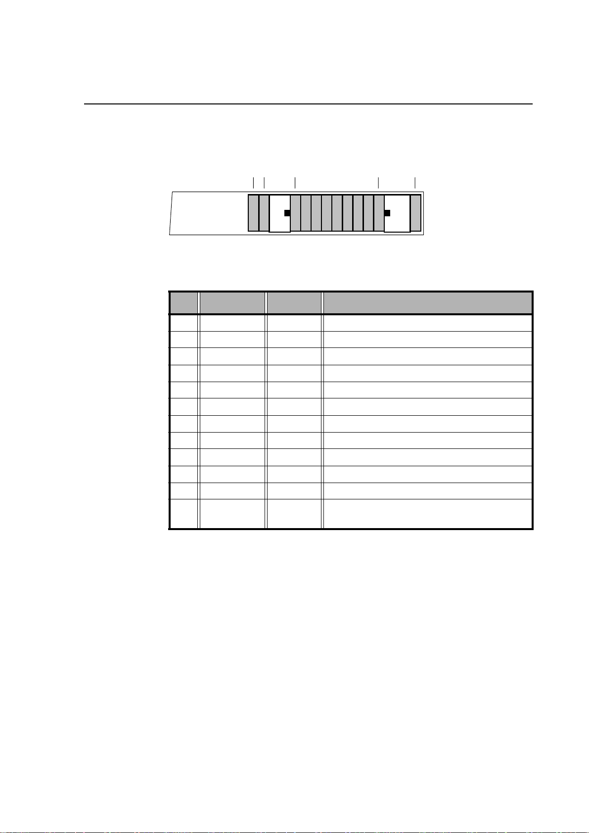
System Connector Signals
External units are connected to the Transceiver Board via the 12-pin System Connector.
12 3 11 12
Pin Signal In/Out Function
1 AFMS Out Audio From Mobile Station
Service Instructions
2 ATMS In Audio To Mobile Station
3 EXTAUD In External Analog Audio Accessory Sense
4 AGND Audio Signal Ground, 0V reference
5 PORTHF In Portable Handsfree
6 MUTE Out Music Mute
7 VPPFLASH In Flash Memory Voltage and Service Voltage
8 VDD Out Logic Reference, Status ON
9 DFMS Out Data From Mobile Station
10 GND Digital Ground and DC Return
11 DTMS In Data To Mobile Station
12 DCIO In/Out DC positive pole for phone battery charging
and external accesso ry powering
5
Page 6
Service Instructions
y
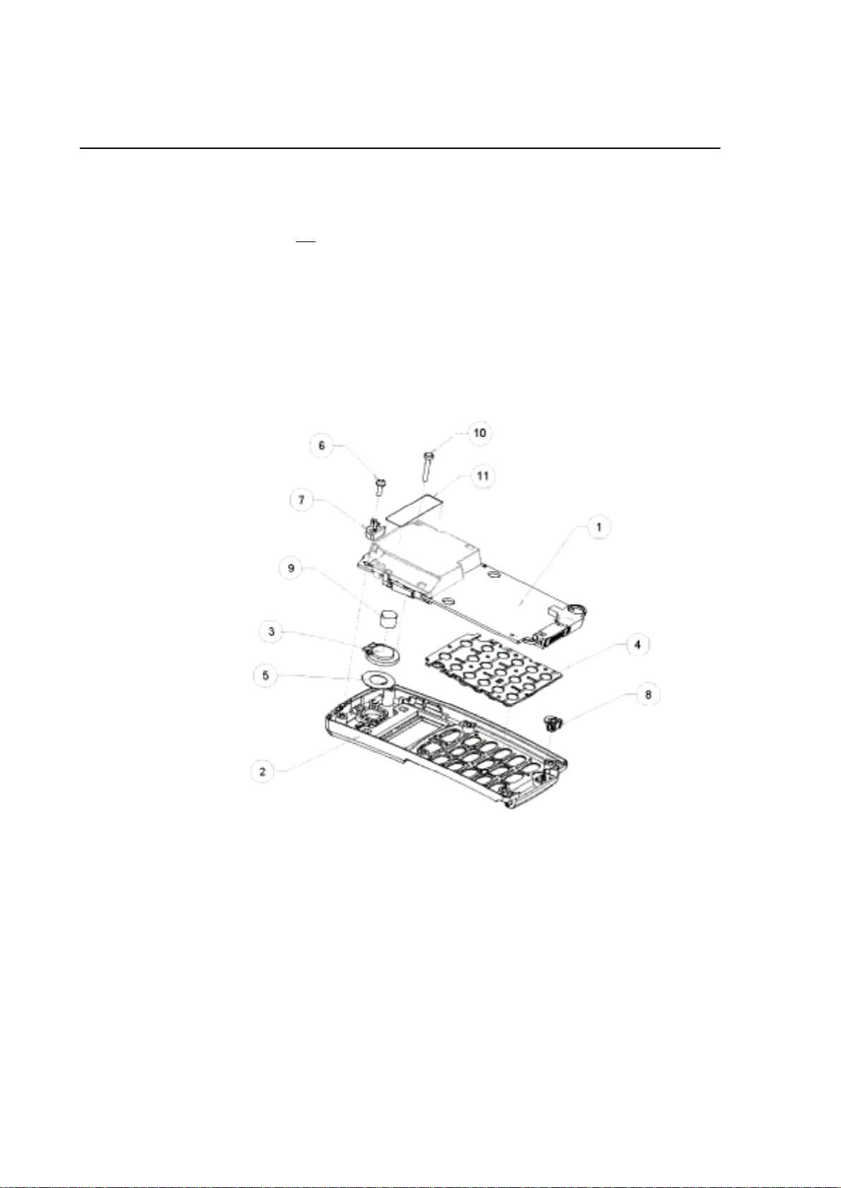
Disassembl
1. Remove the battery and the antenna
Before opening the unit for further disassembly, make sure that the parts can be
placed on a
NOTE!
2. Place the phone on its front and remove four screws with the appropriate torx
screwdrivers.
3. Remove the back cover carefully from underneath.
4. Loosen the remaining screws (6, 10).
Be careful not to damage the antenna connector (7).
5. Careful ly remove the board (1) from the front cover (2) by lifting it upwards.
6. Remove the keypad (4).
dust-free ESD-protected surface
Do not
touch the display with your fingers!
.
6
Page 7

Reassembl
y
1. Place a front cover (2) on the workbench
2. Carefully place the board (1) into the front cover with the shield can upwards.
3. Drop a screw (10) into the upper right corner hole in the board.
4. Drop an antenna connector (7) into the placement cavity of the antenna connec-
5. Drop a screw (6) into the screw hole in the antenna connector.
6. Mount the back cover (13) on the front cover (12).
7. Drop the four screws (14) into the holes on the back cover.
8. Mount the antenna by screwing it clockwise i nto the thread.
9. Insert the battery pack into the phone and push until a click is heard.
Service Instructions
Assemble the keypad (4).
NOTE! Do not touch the display with your fingers
Tighten the screw with a screwdriver (0.15Nm).
tor placement guide.
Ensure that the locat ing posts of the antenna connector are positioned in the mating holes of the board.
Tighten the screw with a scredriver (0.15Nm).
Hold down the lower part of t h e ba ck c over against the front co ver and press the
upper part of the phone together.
Tighten the screws with a screwdriver (0.15Nm).
7
Page 8

Service Instructions
Flip Mount Inspection
After mountin g the flip;
Hold the telephone upside down and check that the flip is not open.
The flip must be closed as shown in
fig. 1
; not open as shown in
fig. 2
.
Fig. 1: Flip Closed
Fig. 2: Flip Open
Warranty Seal
Place the warranty seal over the right hand torx screw at the bottom.
8
Page 9

Exchanging the Circuit Board
1. Transfer t he EEPROM con ten ts of the phone to the PC a s d esc ribed in section 3,
Test/Service Programs
2. Disassemble as previously described in this section.
3. Exchange the board.
4. Reload the EEPROM customer data into the phone.
5. Check the function of the phone and, if necessary, align as described next in
Fault Finding and Alignment
.
.
Service Instructions
9
Page 10

Service Instructions
Fault Finding and Alignment
The table below shows information about test points and test data of the radio and
logic/audio parts of the board. Th is info rmation wi ll beco me an aid in tes ting as well
as fault finding. In general, the following procedure can be used:
1. Align the boards in the sequence stated below.
2. If a specific value cannot be obt ained, use th e tools mentioned in step 3 below to
trace the reason.
3. The built-in
investigated, and any signal data that may be required is found in the section
Connectors and Signals
nector pins is found.
The telephone is tested, unless otherwise explicitly stated, with DC-power 6.2V
supplied via a dummy battery.
Channel 1 TP-1:1 (RX = 935.0125MHz, TX = 890.0125MHz)
RF Power Off TP-2:8
AFC Active TP-15:2
T e st Pr ogr am
, where the distribution of signals at the respective con-
will provide acces s to the functi on or si gnal to b ecome
Audio Switches On TP-20:3 (TX & RX audio paths unmuted)
SAT Tone Off TP-22:3
Manchester Out Off TP-23:0
Volume 4 TP-25:4 (mid range)
TX Source ATMS TP-27:0
Earpiece External TP-28:2
Compandor Disabled TP-29:0 (disabled)
Softlimiter Off TP-32:0
Green LED Off TP-41:MENU+4:0
Red LED Off TP-41:MENU+5:0
ICTRL Off TP-41:MENU+2:0
Illumination Off TP-41:MENU+6:0
TP = Test Program
The above settings are automatically executed when entering the test program.
For detailed information regarding the adjustments, re fer to subsection
gram
in this section.
Test Pro-
10
Page 11

Service Instructions
Sequence of Adjustments
Item 1: VCTCXO
Purpose:
Checking and, if nece ssary, calibrating the reference fre quency gene rator for the
synthesizers
Test method:
Radio test set in TX mode, measured with a frequency counter
Input signal:
None
Measurement point:
Transmitter frequency at antenna connector
Limit:
890.0125MHz ±200Hz
Procedure:
1. Turn on the transmitter (
2. Disable the AFC (
3. Check the frequency error
4. If the transmitter frequency is not within 890.0125MHz ±200Hz;
enter VCTCXO calibra tion (
5. Press M + # to enable the calibration
6. Use # and * buttons to change value and press M + S to store the new value
TP-2:2
TP-15:0
)
TP-18
)
:)
11
Page 12

Service Instructions
Item 2: RSSI Calibration
Purpose:
Calibration of the RSSI (received signal strength indicator)
Test method:
Radio test set in RX mode
Input signal:
Apply 935.0125MHz RF signal modulated with a 1kHz tone at 5.7k Hz devi ati on at
a level of -115dBm to the antenna connector
Measurement point:
None
Limit:
-115dBm 20 < value < 150
-107dBm 30 < value < 218
-87dBm 50 < value < 279
Procedure:
1. Apply 935.0125MHz RF signal modula ted with a 1kHz t one at 5.7kHz de viation
2. Turn the transm itter on (
3. Disable the AFC (
4. Enter RF sensitivity test (
5. Press M +
6. Press M + # to move to next adjustment
7. Set the signal generator to -107dBm
8. Press M + S to store the value
9. Press M + # to move to next adjustment
10.Set the signal generator to -87dBm
11.Press M + S to store the value
at a level of -115dBm to the antenna connector
TP-2:2
TP-15:0
S
)
TP-9
)
)
12
Page 13

Service Instructions
Item 3: RF Output Power
Purpose:
Checking and, if necessary, calibrating the RF output power
Test method:
Radio test set in TX mode
Input signal:
None
Measurement point:
Output power at the antenna connector measured with an RF power meter
Limit:
Power level Output power
2 +26.5dBm ±0.1dB
3 +22.5dBm ±0.5dB
4 +18.5dBm ±0.5dB
5 +14.5dBm ±0.5dB
6 +10.5dBm ±0.5dB
7 +6.5dBm ±1.0dB
Procedure:
1. Turn the transm itter on (
Check if the output power is within the above stated limits
Check the output power at low (1329), mid (1), and high channels (600)
2. If the output power is not within the above stated limits;
TP-5
use
3. Press M + # to start the calibration and display power level and calibrated value
4. Use # and * to increase/decrease the output power
Press M + S to store the value and step to next power level
5. Press C to turn off TX, restore channel number, and jump to menu 0 (test input)
to calibrate the output power
TP-2:2-7
)
13
Page 14

Service Instructions
Item 4: Maximum Deviation
Purpose:
Checking and, if necessary, calibrating the maximum deviation of the transmitter
Test method:
Radio test set in TX mode
Input signal:
1kHz sine wave signal at 320mV
Measurement point:
At the antenna connector measured with a deviation meter
Tolerance:
±7.2kHz -1dB (6.462 - 7.200 kHz)
Procedure:
1. Set TXSENS programmable gain stage to nominal value (
2. Enable the compandor (
3. Connect a 1kHz sine wave signal at 320mV
4. Turn the transm itter on (
5. Monitor RF peak deviation
6. If the deviation is outside the limits; adjust the deviation
7. Enter
8. Start the trimming by pressing M +
9. Trim audio deviation to 6.462 - 7.200 kHz by pressing # and * to increase/
10.Press M + S to store the value
TP-29:1
TP-2:2
TP-14
decrease the deviation
Allowed trim values are 2 to 13
Trim step size is 0.4dB per step
to ATMS (system connector)
RMS
)
to ATMS (system connector)
RMS
)
#
TP-7
, value 7)
14
Page 15

Service Instructions
Item 5: Nominal Deviation
Purpose:
Checking and, if necessary, calibrating the nominal deviation of the transmitter
Test method:
Radio test set in TX mode
Input signal:
1kHz sine wave signal at 190mV
Measurement point:
At the antenna connector measured with a deviation meter
Limit:
±5.7kHz ±0.5dB (5.38 - 6.02 kHz)
Procedure:
1. Enable the compandor (
2. Connect a 1kHz sine wave signal at 190mVRMS to ATMS (system connector)
3. Turn the transm itter on (
4. Monitor RF peak deviation
5. If the deviation is outside the limits; adjust the deviation
6. Enter
7. Start the trimming by pressing M +
8. Trim audi o d evi at ion to 5.38 - 6.02 k Hz b y p res si ng # and * to increase/decrea se
9. Press M + S to store the value
TP-27
the deviation
Allowed trim values are 2 to 29
Trim step size is 0.4dB per step
TP-29:1
TP-2:2
to ATMS (system connector)
RMS
)
)
#
15
Page 16

Service Instructions
Item 6: SAT Deviation
Purpose:
Checking and, if necessary, calibrating the SAT (Supervisor Audio Tone) deviation
of the transm itter
Test method:
Radio test set in TX mode
Input signal:
None
Measurement point:
At the antenna connector measured with a deviation meter
Limit:
±1.7kHz ±0.5dB (1.60 - 1.80 kHz)
Procedure:
1. Mute the TX audio path (
2. Activate the SAT-tone (
3. Unmute the TX SAT path (
4. Turn the transm itter on (
5. Monitor the SAT deviation
6. If the deviation is outside the limits; adjust the deviation
7. Enter
8. Start the trimming by pressing M + #
9. Trim SAT deviation to 1.60 - 1.80 kHz by pressing # and * to increase/decrease
10.Press M + S to store the value
TP-20:0
TP-22:1
TP-22:4
TP-2:2
TP-22
the deviation
Allowed trim values are 2 to 29
Trim step size is 0.3dB per step
)
)
)
)
16
Page 17

Service Instructions
Item 7: TX Data Deviation
Purpose:
Checking and, if necessary, calibrating the TX da ta deviation of the transmitter
Test method:
Radio test set in TX mode
Input signal:
None
Measurement point:
At the antenna connector measured with a deviation meter
Limit:
±6.4kHz ±0.5dB (6.021 - 6.780 kHz)
Procedure:
1. Mute the TX audio path (
2. Activate the TX Data (
3. Turn the transm itter on (
4. Monitor the TX data deviation
5. If the deviation is outside the limits; adjust the deviation
6. Enter
7. Start the trimming by pressing M +
8. Trim TX Data Deviation to 6.021 - 6.780 kHz by pressing # and * to increase/
9. Press M + S to store the value
TP-23
decrease the deviatio n
Allowed trim values are 2 to 13
Trim step size is 0.4dB per step
TP-20:0
TP-23:1
TP-2:2
)
)
)
#
17
Page 18

Service Instructions
Item 8: AFMS and Harmonic Distortion
Purpose:
Checking and, if necessary, calibrating the deviation of the receiver
Test method:
Radio test set in RX mode
Input signal:
Apply a -50dBm 935.0125MHz RF signal modulated with a 1kHz tone, ±2.3kHz
deviation to the antenna input
Measurement point:
At the AFMS output from the system connector measured with an AC volt meter
Limit:
25mV ±1.5dB (21.035 - 29.710 mV)
Procedure:
1. Enable the compandor (
2. Apply a -50dBm 935.0125MHz RF signal modulated with a 1kHz tone, ±2.3kHz
3. Monitor the AFMS output with a 100kΩ load
4. If AFMS is outside the limits; adjust the AFMS level
5. Enter
6. Start the trimming by pressing M +
7. Trim the AFMS level by pressing # and * to increase/decrease
8. Press M + S to store the value
9. Measure the receiver harmonic distortion
10.Should be less than 4.5% at AFMS using a CCITT filter
TP-29:1
deviation to the antenna input
TP-10
)
#
18
Page 19

Service Instructions
Item 9: Receiver Sensitivity
Purpose:
Checking the receiver sensitivity
Test method:
Radio test set in RX mode
Input signal:
Apply an RF signal at low, mid, and high channel modulated with a 1kHz tone at
5.7kHz deviation at a level of -113dBm to the antenna input
Measurement point:
At the AFMS output from the system connector measured with an AC volt meter
Limit:
Better than 20dB SINAD at low, mid, and high channel
Procedure:
1. Select channel (
2. Disable AFC (
3. Turn the transm itter on
4. Apply an RF signal at low, mid, and high channel modula ted wi th a 1kHz to ne at
5.7kHz deviation at a level of -113dBm to the antenna input
5. Measure better than 20dB SINAD on AFMS using a CCITT filter
TP-1:1329, 1, or 600
TP-15:0
)
(TP-2:2
)
)
19
Page 20

Service Instructions
20
 Loading...