

Ericsson EDN612, ESN212, EPN210 Installation Manual
EDN612, ESN212, EPN210 Installation
Guide
EDA 1200

EDN612, ESN212, EPN210 Installation
Guide
EDA 1200
.
ii
3/1531-HSD 101 41 Uen E 2007-08-13
Copyright
© Ericsson AB 2006-2007. All Rights Reserved
Disclaimer
No part of this document may be reproduced in any form without the written
permission of the copyright owner.
The contents of this document are subject to revision without notice due to
continued progress in methodology, design and manufacturing. Ericsson shall
have no liability for any error or damage of any kind resulting from the use of
this document.

.
3/1531-HSD 101 41 Uen E 2007-08-13
iii
Contents
1
Introduction 1
1.1
Revision History 1
1.1.1
This Revision 1
1.1.2
Version D 1
1.1.3
Version C 2
1.1.4
Version B 2
1.1.5
Version A 2
2
Tools 3
3
Overview of the EDN612, ESN212, EPN210 4
4
Power Requirements and Distribution 7
5
Environmental and Space Requirements 9
6
Installation 11
6.1
Preparation for Installation 11
6.2
Mounting the EDN612, ESN212 and EPN210 Nodes 11
6.2.1
Setting the Switch ID in ESN212 12
6.2.2
Mounting the Hardware 15
6.2.3
Cabling of Ethernet Connections (No.1) 15
6.2.4
Cabling the Power Connections (No.2 and No.4) 16
6.2.5
Cabling the Subscriber Line (No.3) 16
6.2.6
SFP Cages for ESN212 18
6.3
Mounting the Front Cover for the Cable Tray 19
7
Initial Configuration and Commissioning 20
7.1
Embedded Nodes 20
7.2
Stand Alone ESN212 20

Contents
iv
3/1531-HSD 101 41 Uen E 2007-08-13
8
Installing and Upgrading the Software 22
9
Verification of the Installation 23

Introduction
3/1531-HSD 101 41 Uen E 2007-08-13
1
1 Introduction
This document describes the installation of the EDN612 IP DSLAM,
ESN212 Switch and Ethernet Power Node EPN210. It is intended for
planning and installation personnel.
The guide can be read separately, but for a full understanding of the EDA
system the reader is referred to the System Description and EDN612,
ESN212, EPN210 User Guide.
The guide can be printed on a monochrome printer, but the illustrations are
easier to understand if a color printer is used.
1.1 Revision History
The guide is valid for EDA 1200 4.0 R3A and later. Please refer to the
Release Notes for valid versions of the nodes. Other product versions, with
functions not described in this guide, may be available.
1.1.1 This Revision
Other than editorial changes, this document has been changed as follows:
• Environmental and Space Requirements section added (section 5 on
page 9).
1.1.2 Version D
Other than editorial changes, this document has been changed as follows:
• Warning in section 6.2.1 on page 12 about not to use other SID than
zero removed.
• The description of the subscriber cable used for connection to the
EDN612 has been revised.
• Tools needed section added (section 2 on page 3)
• Procedure for inserting subscriber line connector revised (section 6.2.5
on page 16).

Introduction
2
3/1531-HSD 101 41 Uen E 2007-08-13
1.1.3 Version C
Other than editorial changes, this document has been changed as follows:
• Initial configuration for stand alone ESN212 added
1.1.4 Version B
Other than editorial changes, this document has been changed as follows:
• Hardware mounting instructions added
• Switch ID setting instructions added
1.1.5 Version A
This is the first version.
Tools
3/1531-HSD 101 41 Uen E 2007-08-13
3
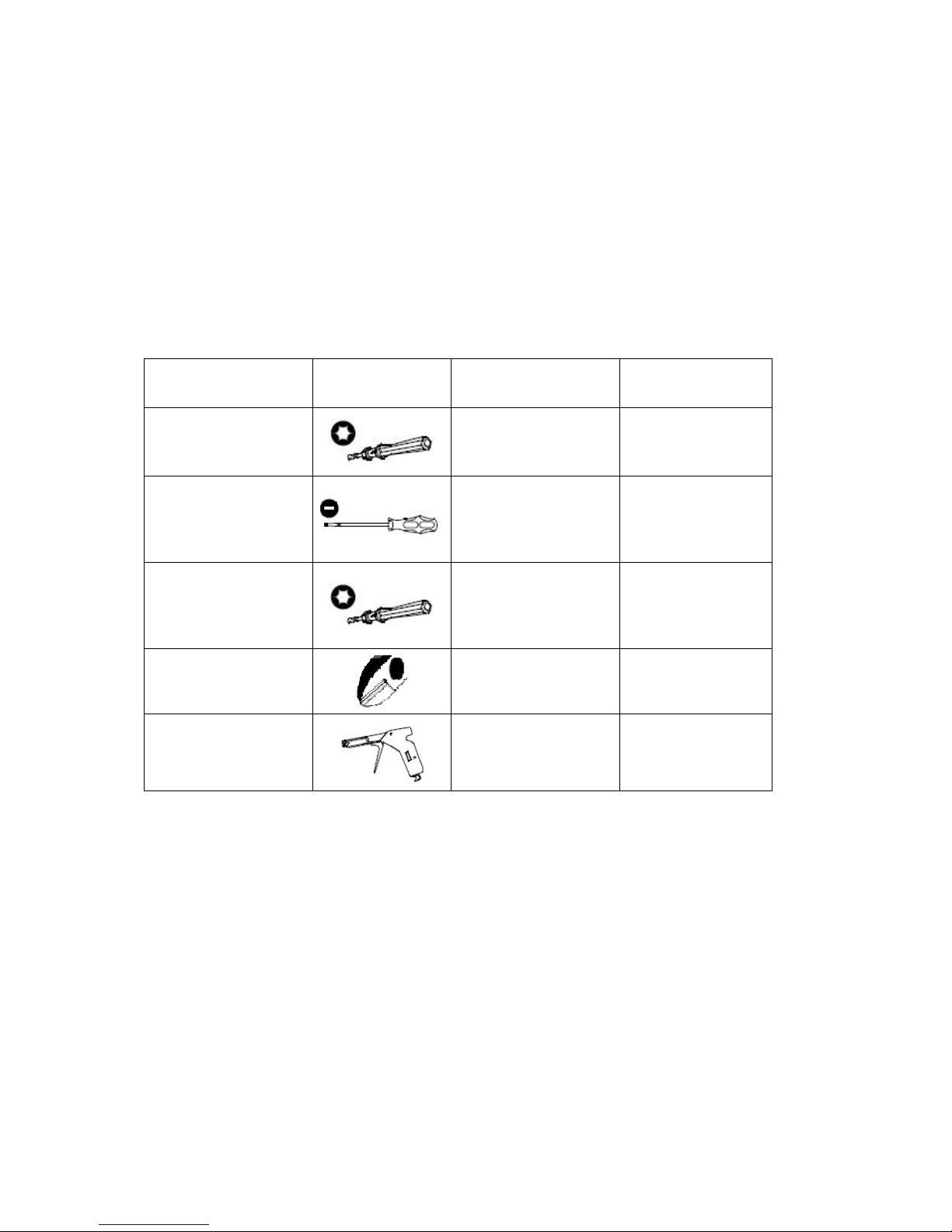
2 Tools
Before starting the installation the following tools should be at hand:
Table 1 Tools and Recommended Torque
Item Shape Used for Recommended
Torque
1.
Torque-driver
with TORX T08
bit
Power and
subscriber
connectors screws
0.3 Nm
2. Small flat head
screw driver
Opening cover for
and setting the DIP
switch of the
ESN212
-
3. Torque-driver
with TORX T30
bit
Screws (M6x16 mm)
for fastening units
and subracks to the
cabinet
10 Nm
4. Side-cutting
pliers
Cutting cable ties
-
5. Band tensioner
Tensioning cable ties
-
Apart from the tools some cable ties for fastening of the cables are needed.
The cable ties are not delivered with the equipment.
Overview of the EDN612, ESN212, EPN210
4
3/1531-HSD 101 41 Uen E 2007-08-13
3 Overview of the EDN612, ESN212,
EPN210
The subrack is available in various configurations that can be adapted to
specific solutions.
The 19” subrack and the ETSI (21”) subrack can both be equipped with up
to 96 End-user lines. The subracks have a built-in cable tray and air guide
and it is possible to mount EDN612 IP DSLAMs, ESN212 switches,
external splitters, and an optional EPN210 Power Distribution Node in
different combinations. Table 2 and Table 3 on page 4 show examples on
various configurations.
Table 2 Examples of Possible Configurations in an ETSI Subrack
Number of
lines
Splitter EDN612 ESN212 EPN210
96 0 8 1 1
96 0 8 1 0
72 6 6 1 0
60 5 5 1 1
Table 3 Examples of Possible Configurations in a 19” Subrack
Number of
lines
Splitter EDN612 ESN212 EPN210
96 0 8 1 0
84 0 7 1 1
60 5 5 1 0
48 4 4 1 1
Overview of the EDN612, ESN212, EPN210
3/1531-HSD 101 41 Uen E 2007-08-13
5
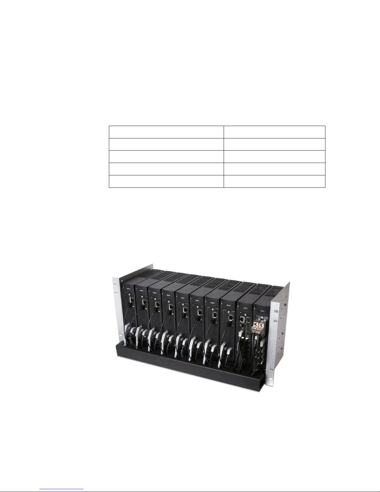
Table 4 on page 5 shows the dimensions for the nodes in the subrack
solutions.
Table 4 Size Dimensions for Subrack Solutions
Nodes Size
ETSI (inside) 481 mm
19” (inside) 431 mm
EDN612, ESN212 or EPN210 47 mm
Splitter 23 mm
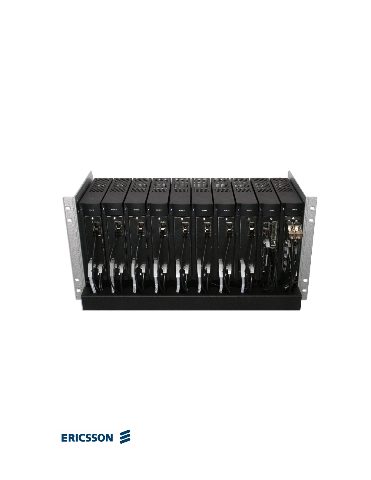
Figure 1 on page 5 shows a fully equipped 96-line ETSI subrack solution
without splitters with eight EDN612 IP DSLAMs, one ESN212 switch, and
one EPN210 Power Distribution Node.
Figure 1 96-line ETSI Subrack with EDN612, ESN212 and EPN210
 Loading...