

Ericsson PORTABLE FM RADIO, EDACS Μ−PΑ Maintenance Manual
Mobile Communications
LBI-38602A
EDACS
Μ−PΑ
UHF SYSTEM MODEL
PORTABLE FM RADIO
TABLE OF CONTENTS
REAR COVER ASSEMBLY . . . . . . . . . . LBI-38383
FRONT COVER ASSEMBLY (LATER)
LESS CONTROL BOARD . . . . . . . . . . . LBI-38834
CONTROL BOARD (LATER) . . . . . . . . . LBI-38828
UHF SERVICE SECTION . . . . . . . . . . . LBI-38604
Maintenance Manual

LBI-38602
TABLE OF CONTENTS
SPECIFICATIONS . . . . . . . . . . . . . . . . . . . . . . . . . . . . . . . . . . . . . . . . . . . . . . . . . . 3
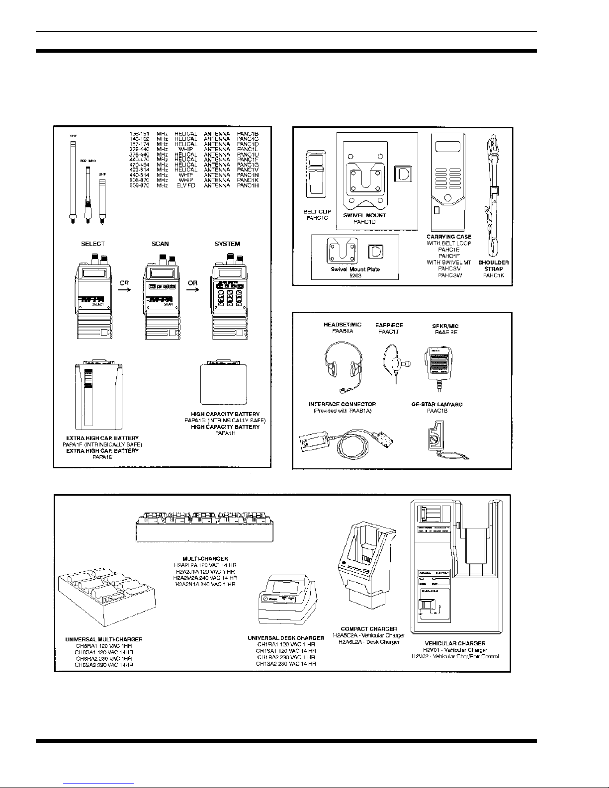
OPTIONS AND ACCESSORIES . . . . . . . . . . . . . . . . . . . . . . . . . . . . . . . . . . . . . . . . . . . 4
INTRODUCTION . . . . . . . . . . . . . . . . . . . . . . . . . . . . . . . . . . . . . . . . . . . . . . . . . . . 5
DESCRIPTION . . . . . . . . . . . . . . . . . . . . . . . . . . . . . . . . . . . . . . . . . . . . . . . . . . . . 6
Rear Co v e r Assembly . . . . . . . . . . . . . . . . . . . . . . . . . . . . . . . . . . . . . . . . . . . . . . 7
Front Cover Assembly . . . . . . . . . . . . . . . . . . . . . . . . . . . . . . . . . . . . . . . . . . . . . . 7
Antennas . . . . . . . . . . . . . . . . . . . . . . . . . . . . . . . . . . . . . . . . . . . . . . . . . . . . . 7
Batteries . . . . . . . . . . . . . . . . . . . . . . . . . . . . . . . . . . . . . . . . . . . . . . . . . . . . . 7
Rechargeable Battery Pack Disposal . . . . . . . . . . . . . . . . . . . . . . . . . . . . . . . . . . . . . . 8
Universal Device Connector . . . . . . . . . . . . . . . . . . . . . . . . . . . . . . . . . . . . . . . . . . . 8
PROGRAMMING . . . . . . . . . . . . . . . . . . . . . . . . . . . . . . . . . . . . . . . . . . . . . . . . . . 9
OPERATION . . . . . . . . . . . . . . . . . . . . . . . . . . . . . . . . . . . . . . . . . . . . . . . . . . . . . 9
Antenna/Radio/Battery Assembly . . . . . . . . . . . . . . . . . . . . . . . . . . . . . . . . . . . . . . . . 9
Alert Tones . . . . . . . . . . . . . . . . . . . . . . . . . . . . . . . . . . . . . . . . . . . . . . . . . . . . 9
Self-Test . . . . . . . . . . . . . . . . . . . . . . . . . . . . . . . . . . . . . . . . . . . . . . . . . . . . . 9
Trunked Operation . . . . . . . . . . . . . . . . . . . . . . . . . . . . . . . . . . . . . . . . . . . . . . . . 9
Conventional Operation . . . . . . . . . . . . . . . . . . . . . . . . . . . . . . . . . . . . . . . . . . . . . 10
Scan Operation - Trunked Mode . . . . . . . . . . . . . . . . . . . . . . . . . . . . . . . . . . . . . . . . 11
Scan Operation - Conventional Mode . . . . . . . . . . . . . . . . . . . . . . . . . . . . . . . . . . . . . . 11
Special Calls . . . . . . . . . . . . . . . . . . . . . . . . . . . . . . . . . . . . . . . . . . . . . . . . . . . 12
Operating Tips . . . . . . . . . . . . . . . . . . . . . . . . . . . . . . . . . . . . . . . . . . . . . . . . . . 13
Page
INTRINSICALLY SAFE USAGE . . . . . . . . . . . . . . . . . . . . . . . . . . . . . . . . . . . . . . . . . . 14
MAINTENANCE . . . . . . . . . . . . . . . . . . . . . . . . . . . . . . . . . . . . . . . . . . . . . . . . . . . 14
Preventive Maintenance . . . . . . . . . . . . . . . . . . . . . . . . . . . . . . . . . . . . . . . . . . . . 14
ILLUSTRATIONS
Figure 1 - UDC Pin-Out . . . . . . . . . . . . . . . . . . . . . . . . . . . . . . . . . . . . . . . . . . . . 8
Figure 2 - Operating Controls . . . . . . . . . . . . . . . . . . . . . . . . . . . . . . . . . . . . . . . . . 12
Figure 3 - System Model Front Panel And Keypa d Outline Diagra m . . . . . . . . . . . . . . . . . . . . . 15
Figure 4 - Rear Cover Assembly Block Diagram . . . . . . . . . . . . . . . . . . . . . . . . . . . . . . . 16
Figure 5 - Front Cover Assembly Block Diagram . . . . . . . . . . . . . . . . . . . . . . . . . . . . . . . 17
NOTE
The software contained in this device is copyrighted by Ericsson GE Mobile Communications, Inc. Unpublished rights
are reserved under the copyright laws of the United States.
This manual is published by
Ericsson GE Mobile Communications Inc.
, without any warranty. Improvements and
changes to this manual necessitated by typographical errors, inaccuracies of current information, or improvements to programs and/or equipment, may be made by
Ericsson GE Mob ile Communications Inc.
, at any time and without notice.
Such changes will be incorporated into new editions of this manual. No part of this manual may be repro du ce d or transmit ted in any form or by any means, electronic or mechanical, inclu ding p hot ocop yi ng an d re cor ding, for any purpo se, with out
the express written permission of
Ericsson GE Mobile Communications, Inc.
Copyright© April 1991, Ericsson GE Mobile C ommunications Inc.
2

SPECIFICATIONS *
GENERAL
Frequency Bands 403 - 423 MHz
450 - 470 MHz
Oscillator Stability 2.5 ppm
Operating Temperature Range -30°C to + 60°C
Maximum Relative Humidity 90% at 55°C
Battery Voltage 7.5 Vdc (nominal)
Dimensions (H x W x D)
less battery, knobs and antenna 140 x 69 x 38 mm (5.52 x 2.72 x 1.50")
with Extra High Cap. Battery 232 x 69 x 40 mm (9.15 x 2.72 x 1.58")
Weight
less battery 540 grams (19 ounces)
with Extra High Cap. Battery 907 grams (32 ounces)
TRANSMITTER
LBI-38602
Frequency Range 403 - 423 MHz
450 - 470 MHz
Maximum Frequency Separation 20 MHz (no degradation)
FM Deviation ±5 kHz
High/Low RF Power Output 5 Watts / 1 W a tt (program ma ble on a per channel basis)
FM Hum and Noise -45dB (companion receiver)
Spurious and Harmonic Emissions -74 dBc
Audio Response + 1 to -3dB (6 dB/octave pre-emphasis from 300 to 3 kHz)
Audio Distortion less than 3% (at 1000 Hz tone, 3 kHz deviation)
RECEIVER
Frequency Range 403 - 423 MHz
450 - 470 MHz
Maximum Frequency Separation 20 MHz (no degradation)
Sensitivity (12 dB SINAD) -116 dBm (0.35 µV)
Adjacent Channel Selectivity (typical) -75 dB at 25 kHz
Critical Squelch 10 dB SINAD
Intermodulation (typical) -75 dB
Spurious and Image Rejection -75 dB
Audio Output (24 ohms load impedance) 500 mW (less than 5% distortion)
* These sp ecifications are intended primarily for the use of the serviceman. See the appropriate Specifications Sheet for the
complete specifications.
3
LBI-38602
OPTIONS AND ACCESSORIES
Radios, Antennas, Batteries
Carrying Accessories
Audio Accessories
Chargers
4

INTRODUCTION
The EDACS M-PA UHF System model radio is a
high quality microprocessor controlled synthe s i zed portable FM radio. The unit complements the digitally
trunked system by providing a sm all , rugged, easy to operate and easy to program portable radio for the UHF
trunking environment. The radio also provides conventional communications in the UHF spectrum. The unit
meets or exceeds all APCO 16 portable radio equipment
requirements for digitally trunked and conventional
communications.
Trunked and conventional operation with the
EDACS M-PA radio is highlighted by its programming
versatility. Many fe atu re s ar e PC pr og rammable. This allows tailored operation of the portable radio to meet the
needs of the radi o s ys t em and the individual us ers.
The EDACS M-PA System model personality allows up
to 50 systems with 16 groups each, or 16 systems with 50
groups each, to be programmed and selected. Up to 48 conventional channels can be stored in the radio. Ninety-nine
special calls can be stored. Special calls include individual
and telephone interconnect calls. DTMF operation is supported by the front panel 16-button ke yp ad.
LBI-38602
Programmable Multiple Group Capability
•
radio can communicate with many groups within a
system. A maximum of 50 groups per system can be
assigned and selected.
The user pre-programs (via PC computer) the unit so
the Control Knob makes the group or group selection.
If the Control Knob is programmed for group selection, up to 16 groups can be selected; up to 50 systems can then be selected by the STEP button. If the
Control Knob is programmed for system selection, up
to 16 systems can be selected; up to 50 groups can
then be selected via the STEP button.
Programmable Group Call Capability
•
can simultaneously call all units within a group.
Special Call Mode
•
communication via special (individual) calls. Up to
99 special calls can be pre-programmed into the
radio.
Remote Dynamic Regrouping Capability
•
dispatch center can regroup radios for multi-agency
communications.
Remote Disable
•
remotely disabl e d by th e S yst em Manager.
- Trunked operation allows
- If lost or stolen, the unit may be
- The unit
- The
- The
Radios operating in the trunk mode monitor a common
control channel from the s ite for channel assignments. This
designated control channel is the digital data link to/from
the radio and the site controller.
Working channels are allocated by the site via the control channel. Working channels carry the actual voic e signal.
The allocated working channel may change several times
during a communication sequence. This change, if needed,
occurs at the start of a transmission sequence (at PTT time)
under the supervision of the site. Working channel access
time is typically 250 milliseconds and does not exceed 500
milliseconds as specified by the APCO 16 requirements.
When trunking operation is not wanted or is not possible, the unit can operate in the conventional mode. In the
conventional mode, the radio operates on 25 kHz allocated
channels.
TRUNKED FEATURES
Features which specifically apply to trunked mode
operation are listed below.
Programmable Multiple System Capability
•
Selection of up to 50 maximum systems (with 16
groups each) is capable. The radio can operate on
different trunked sites or on different systems on the
same site.
-
TRUNKED AND CONVENTION AL
FEATURES
The M-PA System model radio has the following
features that apply to both trunked and conventional operation. Up to 48 conventional channels can be programmed into the radio.
Rotary Control Knob
•
mounted control allows easy selection of systems,
groups or conventional channels, according to how
the unit is programmed.
Volume Control Knob
•
provides quick and easy adjustments to the volume
level. Minimum volume levels can be programmed
into the unit. This feature prevents missed calls due to
a low volume setting.
Backlit Liquid Crystal Display
•
alphanumeric display provides programmable
customi zat io n and fe ed back to t he op er ato r of variou s
operating conditions. Icons (flags) located above and
below the digits alert the operator to various radio
conditions such as no control channel, conventional
mode enabled, transmitter in operation and a low
battery condition. Backlighting can be enabled or
disabled on a per chan nel or per group basis.
- The 16-position top-
- This rotatable control
- The 8-digit
5

LBI-38602
• 16-Button Keypad - This front panel keypad allows
easy operat or control of functions such as system or
group selection, scan operation, special call mode,
and manual dialing for telephone interconnect and/or
individual calls.
• Sca n Operation - Trunked groups and conventional
channels can be scanned. Trunked groups which have
been previously added to the scan list (via the
operator) may be scanned. In conventional mode, the
radio may be configured for a fixed priority-one
channel, the selected channel as priority-one, a fixed
scan list, or a front keypad programmed scan list.
Dual-priority scan is supported in conventional mode.
• Telephone Interconnect - Special call mode al lows
the operator to select and send pre-programmed
telephone calls. Telephone interconnect is performed
by the site. DTMF operation is supported by the front
panel keypad.
• Programmable via the Universal Device Connector
(UDC) - The entire operation of the radio can be
field customized by programming the unit using an
IBM PC or compatible computer. The programmed
personality is stored in a battery (internal lithium)
backed-up RAM.
• Simple Remote Control Capability - External
accessories can be connected to the UDC such as a
headset, a speaker-mic or a lanyard. Connection of
the speaker-mic allows the operator to remotely
control PTT operation and audio level of the external
speaker. An antenna jack is located on the UDC for
the connection of a remote mounted antenna such as
when the radio is used in a vehicular charger or
repeater.
• Emergency Signalling Feature - Pressing a single
recessed button instantly sends an alert message on a
pre-programmed channel. The radio ID number is
transmitted and the unit is given top priority in the
system. Emergency signalling can also be enabled by
a lanyard connected to the UDC.
• Programmable Carrier Control Timer - A
programmable transmit time will automatically
disable the transmitter and provide an alerting tone
after time-out. This feature prevents radio damage and
unnecessary channel traffic in the event of a "stuck"
mic. CCT is reset on every PTT and the alert tone is
removed upon release of the PTT button.
• Programmable Transmitter Power Levels -
Transmitter power level (high or low) is PC
programmable into the radio such that it is
automatically selected channel-by-channel.
• Automatic Squelch - Squelch operation in the
trunked mode is automatically controlled. In
conventional operation, squelch threshold can be
programmed on a per channel basis. Squelch circuits
are designed so that annoying squelch pops, which
may occur at the end of a received message, are
minimized.
• Programmable Multi-Tone Channel Guard
(CTCSS) - Channel Guard tone frequencies within
the range of 67 H z to 210.7 Hz, including all of the
standard EIA frequencies, may be programmed,
encoded and decoded.
• Programmable Multi-Code Digital Channel
Guard - Similar capability as with Tone Channel
Guard is provided.
• Two-Tone Sequential (T99) Decode - Selective
calling decode is enabled or disabled on each
individual channel. Two sets of three unique decodes
are available to allow large systems the capability of
individual and group calls. Sets are selectable on a
per system basis.
• Channel Busy Lockout - Personality information
includes the capability to prevent the transmitter from
operating on a channel where carrier activity is
present. The channel busy indicator, the "BSY" flag,
is active during this time. This feature is selectable on
an overall radio basis.
• Repeater Talkaround - Allows communication with
another portable or mobile radio when out of range of
the repeater.
• Alert Tones - Alert tones prompt the operator of
various radio conditions such as channel access, CCT
time-out or a low battery.
• Self-Te st - At power-up the unit automatically
performs a diagnostic test on itself and reports any
found errors via th e LCD.
DESCRIPTION
The EDACS M-PA portable radio consists of two
major assemblies, the Front and Rear Covers. These two
assemblies house all of the units RF, analog and digital
circuitry in the weather resistant die-cast aluminum case.
The assemblies are electrically interconnected by two
single-in-line type connectors.
The battery pack slides and locks on to the bottom
of the unit. The on/off switch for the radio is located on
the battery pack. Battery packs are available in several
different capacities.
6
 Loading...