

Page 1

Operator’s Manual
EDACS® PRISM HP
Radio
ericssonz
Page 2

NOTICE!
This manual covers Ericss on and General Electric
products manufactured and s old by Ericsson Inc.
NOT E!
Repairs to this equipment should be made only by an
authorized service technician or facility designated by
the supplier. Any repairs, alterations or substitution of
recommended par ts made by the user to this equipment
not approved by the manufacturer could void the use r’s
authority to operate the equipment in addition to the
manufact urer’s warranty.
NOTE
The software contained in this device is
copyrighted by Er icsson I nc. Unpublished rights
are reserved under the copyright laws of the
United States.
This man ual is publis hed by Er icss on Inc. , wit hout any warranty . Improvements and changes
to this manual necessitated by typograph ical errors, inaccuracies of current informat ion, or
improve ments to programs and/or equip ment, may be made by Er icsson Inc., at any time an d
without notice. Such changes will be inc orporated into new editions of t his manual. No part of
this manual may be reproduced or transmitted in any form or by any means, electronic or
mechan ical, including pho tocopying and recordi ng, for any purpos e, without the ex press written
permission of Ericsson Inc.
Copyri ght © July 1995 , Ericsso n Inc.
2
Page 3

TABLE OF CONTENTS
INTRODUCTI O N . . . . . . . . . . . . . . . . . . 7
USER INTE RFAC E . . . . . . . . . . . . . . . . . 8
BUTTONS AND KNOBS . . . . . . . . . . . . . 12
KEYPAD . . . . . . . . . . . . . . . . . . . . . 14
Standard Fu nctions . . . . . . . . . . . . . 15
Scan Mode l . . . . . . . . . . . . . . . . . 16
System M odel . . . . . . . . . . . . . . . . 16
BUTTON AND KEYPAD REASSIGNM ENT . . . 18
DISPLAY . . . . . . . . . . . . . . . . . . . . . 19
Radio Stat us I con s . . . . . . . . . . . . . . 20
Hidden Status Icons . . . . . . . . . . . 22
Messages . . . . . . . . . . . . . . . . . . 22
Error Messages . . . . . . . . . . . . . . . 25
UNIVERSAL DEVICE CO NNECTOR (UDC) . . 25
ALERT TONES . . . . . . . . . . . . . . . . . . 25
Call Originat e . . . . . . . . . . . . . . . . . 26
Call Qu eued (Tr unk ed M ode O nly) . . . . . 26
Autoke y (Trunked Mode Only) . . . . . . . . 26
System Busy (Trunked Mode O nly) . . . . . 26
Call Denied (Trunked Mod e O nly) . . . . . . 27
Carrier Co ntrol Timer . . . . . . . . . . . . . 27
Low Batt er y Warning . . . . . . . . . . . . . 27
Low Ba tter y Alert (Transmit Lockout) . . . . 27
Key Press Alert . . . . . . . . . . . . . . . . 28
OPERATION . . . . . . . . . . . . . . . . . . . . 28
TURNING O N THE RADI O . . . . . . . . . . . . 28
SYSTEM/GRO UP/CHANNEL SELECTION . . . 29
System Selection . . . . . . . . . . . . . . . 29
Group or Ch annel Selection . . . . . . . . . 32
TRUNKED MODE OPERATION . . . . . . . . . 34
Receiving A Group Ca ll . . . . . . . . . . . 34
Sending A Group Ca ll . . . . . . . . . . . . 36
Conventional Failsoft . . . . . . . . . . . . . 37
Emerg ency Op eration . . . . . . . . . . . . 37
3
Page 4

TABLE OF CONTENTS (Continued)
Receivin g An Eme rge ncy Call . . . . . 38
Declaring An Em erg ency Call . . . . . 38
SCANNING TRUNKED G RO U P S . . . . . . . . 39
Turning Sc an O n and Off . . . . . . . . 39
SCAN Radio . . . . . . . . . . . . . . . . . . . 40
Adding Group s to a Sc an List . . . . . . . . 40
Deleting Gro ups f rom a Scan List . . . . . . 41
SYSTEM Radio . . . . . . . . . . . . . . . . . 42
Adding Groups To A Scan List . . . . . . . 42
Deleting G r oups From A Scan List . . . 44
SCANNING TRUNKED SYST EMS . . . . . . . . 44
Wide Area System Scanning . . . . . . . . 44
Priority Sy st em Scan . . . . . . . . . . . . 45
ProSound
. . . . . . . . . . . . . . . . . 45
INDIVIDUAL CALLS . . . . . . . . . . . . . . . 46
Receiving And Resp onding To An Individual Call
(Trunked Mode O nly) . . . . . . . . . . . . 46
Sending An Individu al Call
(Trunked Mode O nly) . . . . . . . . . . . . 48
Pre-Stored I ndividua l Calls . . . . . . . 48
System M odel . . . . . . . . . . . . . 48
Scan Mode l . . . . . . . . . . . . . . . 48
Direct Dialing of Individual Calls (Syste m
Model only) . . . . . . . . . . . . . . . 49
Call Storage Lists . . . . . . . . . . . . . . 50
TELEPHONE INTERCO NNECT CALL S . . . . 51
Receiving A Telephone Int erconn ect Call
(Trunked Mode O nly) . . . . . . . . . . . . 51
Sending A Telephone Inter conn ect Call
(Trunked Mode O nly) . . . . . . . . . . . . 51
Pre-Stored Number . . . . . . . . . . . 51
Direct Dialing of Phone Calls (Syst em Mo del
only) . . . . . . . . . . . . . . . . . . 53
DTMF Overdial / Conventional Mode Telephon e
Interconnect . . . . . . . . . . . . . . . . . 54
SCAN Radio: . . . . . . . . . . . . . . 55
4
Page 5

System Radio: . . . . . . . . . . . . . . 56
PROGRAM MABLE ENTRIES . . . . . . . . . . . 57
Prestoring Indiv idual and Te lephon e In terco nnec t
Calls from the Keypad (Syste m Model only) . 57
STATUS/MESSAGE OPERATION . . . . . . . . . 58
STATUS OPERATION . . . . . . . . . . . . . . 58
MESSAGE OPERATION . . . . . . . . . . . . . 59
DYNAMIC REGROUP OPERATION . . . . . . . 59
Emerg ency Op eration . . . . . . . . . . . . 60
MACRO KEY OPERATION . . . . . . . . . . . . . 60
EDACS CONVENTI ONAL P1 SCAN . . . . . . . . 61
MENU . . . . . . . . . . . . . . . . . . . . . . . . 61
PROFEATURE . . . . . . . . . . . . . . . . . . 67
Serial Numbe r ROM (12 Hex Digits) . . 68
Feature Encryption Data Str eam . . . . 68
Number Fields . . . . . . . . . . . . . . 69
Features Enabled . . . . . . . . . . . . 70
AEGIS OPERATION . . . . . . . . . . . . . . . . 71
VOICE MODES . . . . . . . . . . . . . . . . . . 71
Mode 1: Clear Mod es . . . . . . . . . . . . 71
Mode 2: Aegis Digital Mode . . . . . . . . . 71
DTMF . . . . . . . . . . . . . . . . . . . . . 72
Mode 3 : Aegis Pr iv ate M ode s . . . . . . . . 72
Transfe rring Keys Into the Radio . . . . . . . 73
Displaying The Cur ren tly Use d Crypto gra phic
Key Numb er . . . . . . . . . . . . . . . 74
System Encryption Key . . . . . . . . . 75
Group/Channel Encrypt ion Key . . . . . 75
Key Ze ro . . . . . . . . . . . . . . . . . 76
Private Operation . . . . . . . . . . . . . . 76
POR TABLE DATA . . . . . . . . . . . . . . . . . . 78
Receivin g An Encr ypted Call . . . . . . 76
Trans mit tin g An Encr ypt ed Call . . . . . 76
Scanned G r oup Calls . . . . . . . . . . 77
5
Page 6

TABLE OF CONTENTS (Continued)
DISPLAYS . . . . . . . . . . . . . . . . . . . . 79
DATA OFF OPERATION . . . . . . . . . . . . . 80
DATA ON OPERATION . . . . . . . . . . . . . 80
EXITING DATA CALLS . . . . . . . . . . . . . . 80
SCAN LOCKO UT M ODE . . . . . . . . . . . . 81
DATA LOCKOUT MODE . . . . . . . . . . . . . 82
CONVENTIONAL MODE OPERATION . . . . . . 82
Receiving A Call . . . . . . . . . . . . . . . 83
Sending A Call . . . . . . . . . . . . . . . . 83
Adding Chann els To A Scan List . . . . . . 84
Deleting C hannels From A Scan List . . . . 85
Turning Sc an O n . . . . . . . . . . . . . . 86
Turning Sc an O f f . . . . . . . . . . . . . . 87
OPERATING RULES AND REGULATIONS . . . . 87
OPERATING TIPS . . . . . . . . . . . . . . . . . 89
BATTERY PACKS . . . . . . . . . . . . . . . . . 89
CHARGING THE BATTERY PACK . . . . . . . 89
RECHARGEABLE BATTERY P ACK DISPO SA L 91
INSTALLING THE BATTE R Y PACK . . . . . . . 91
REMOVING THE BATTERY PACK . . . . . . . 92
INTRINSICALLY SAFE USAG E . . . . . . . . . . 93
BATTERY PACKS . . . . . . . . . . . . . . . . 93
GLOSSARY . . . . . . . . . . . . . . . . . . . . 94
WARRANTY . . . . . . . . . . . . . . . . . . . . 99
NICKEL-CADMI UM BATTERY W ARRANTY . . . 100
OPERATOR’S RADIO SETUP . . . . . . . . . . . 101
6
Page 7

INTRODUCTION
This manual describes how to use the EDACS
PRISM HP Radio. The PRISM HP is a synthesized,
microprocessor-based, high performance portable FM
radio providing reliable two-way commu nications in both
the Enhanced Digital Access Communications System
(EDACS) trunking environment and conventional communication systems.
In the EDACS or trunked system mode, the user
selects a communications system and group. In this
mode, channel sel ection is transparent to the user and
is controlled via digital communication with the system
controller. This provides advanced programmable features and fast access to communicat ion channels.
In the conventional mode, the user se lects a channel
and directly communicates on that channel. In this mode,
a system refers to a set of channels. A channel is a
transmit/receive radio frequency pair.
7
Page 8

USER INTERFACE
The PRISM HP operating contro ls are located on the
radio’s front, top and left panels. A 6-butt on (scan m odel)
or 15-button (syst em model) keypad, Liquid Crystal Display (LCD), microphone and speaker are on the front
panel. The top panel houses a rotar y SYSTEM/GROUP/
CHANNEL knob, POWER ON-OFF/VOLUME control
knob and an EMERGENC Y button. An OPTI ON button,
CLEAR/MONITOR button and the Push-To-Talk (PTT)
button are all located on the left side panel. The Universal
Device Connector (UDC) is located on the right panel
and is used while programming the r ad io and for acces sory connection. A battery rel ease button is located on
the back adjacent to the PPT button.
The display has three, twelve character alphanumeric
lines used to show the operational mode of the radio. A
back light illuminates the display and the keypad for
nighttime us e. An LED is located on the front top edge of
the radio. Red indicates transmit.
8
Page 9
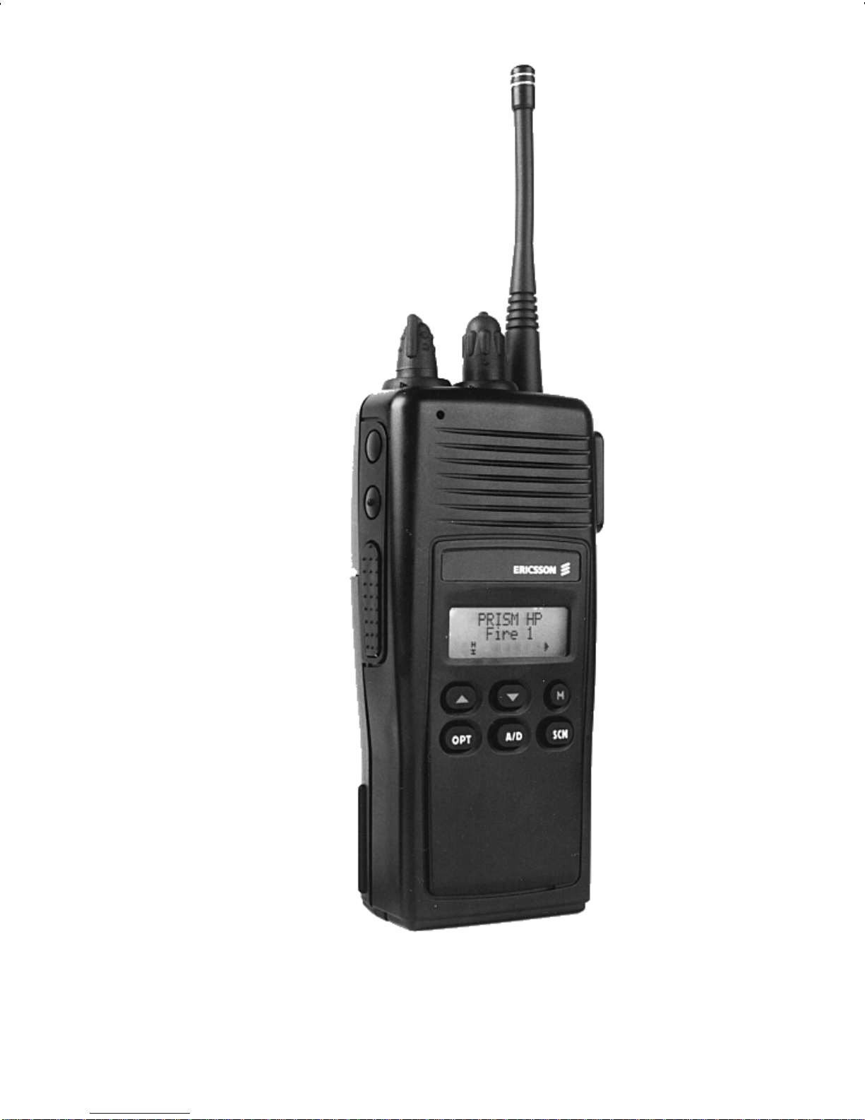
Figure 1 - PRSM HP Radio
(Scan Model)
9
Page 10

Figure 2 - PRSM HP Radio
10
(System Model)
Page 11
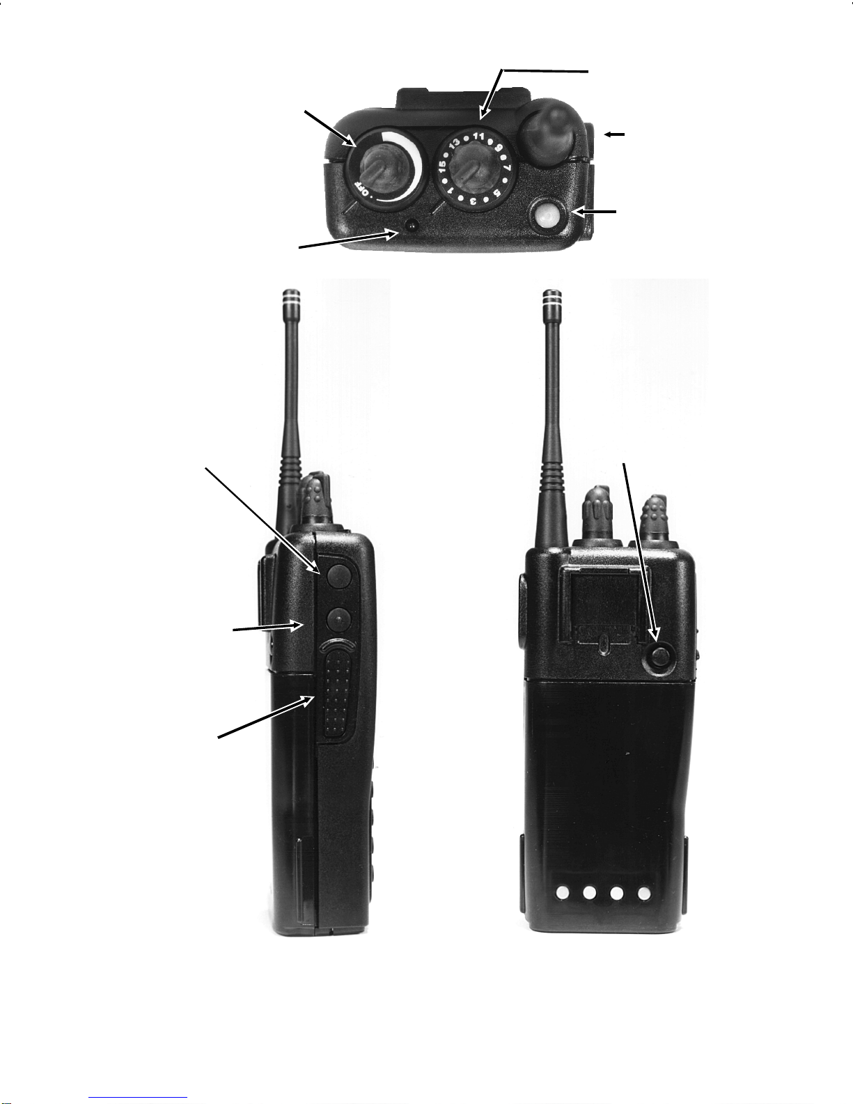
POWER ON-
Antenna
OFF/VOLUME
Knob
TX LED
OPTION
Button
SYSTEM/GROUP/
CHANNEL Knob
EMERGENCY
Button
BATTERY
RELEASE
Button
CLEAR/
MONITOR
Button
Push-To-Talk
(PTT) Button
Figure 3 - Top, Back And Left Panel Views
11
Page 12

BUTTO NS AND KNO BS
This section describes the primary function of the
button and knob controls. Other functions associated
with these controls are deta iled in later sections.
SYSTEM/
GROUP/
CHANNEL
KNOB
POW ER
ON-OFF/
Selects systems or groups/channels
(depending on programming). This
is a 16 - position rotary knob. See
SYSTEM/ GROUP/CHANNEL SELECTION for details.
Note: The radio is supplied with a
mechanical stop which can, if desired, limit the posit ions accessed. If
the knob will not access all positions
do not force it.
Applies power to the radio and adjusts the rec eiver’s vo lume. Rot ating
VOLUME
KNOB
the control clockwise applies power
to the radio. A single alert tone (if
enabled through programming) indicates the radio is operational.
Rotating the control clockwise increases the volume level. Minimum
volume levels may be programmed
into the radio to prevent missed calls
due to a low volume setting. While
adjusting the volume t he display will
momentarily indicate the volume
level (i.e. VOL = 31). The volume
range is from a minimum pro-
12
Page 13

grammed leve l of zero (displayed as
OFF in the display) up to 31 which is
the loudest level.
EMERGENCY/
HOME BUTTON
OPTION
BUTTON
The EMERG ENCY/ HO ME but ton is
used to automatically select a preprogrammed Group/System by
pressing and holding for a programmed duration. It can also be
used to declare emergency by
pressing and holding for programmed dur ation. T he but ton must
be pre-programmed for either operation, not bot h.
Programmable per system.
CLEAR/
MONITOR
BUTTON
Serves several purposes depending
on the operating mode. In trunked
mode, the CLEAR/MONITOR button
exits the current operation and removes all displays associated with it.
The radio and display then return to
the group receive state. In conventional mode, press ing this but ton unmutes the receiver so activit y on the
selected channel can be monitored.
When pressed and held f or appr oximately 3 seconds, this button toggles conventional channel decoding/encoding (Channel Guard, Digi-
tal Channel Guard) on and off if programmed for the s elected channel.
13
Page 14

PUSH-TO-TALK
Enables the radio’s transmitter for
BUTTON (PTT)
voice communication. Releasing
PTT returns the radio to the receive
mode.
KEYPAD
The keypad layout has a to tal of 6 or 15 keys. The
keys have special functions and are labeled as such
using a symbol or abbreviated word describing its primary function. Numeric entry is a secondary function of
the keys. Each key is described below.
Figure 4 - PRISM HP Keypad (Scan Model)
14
Page 15
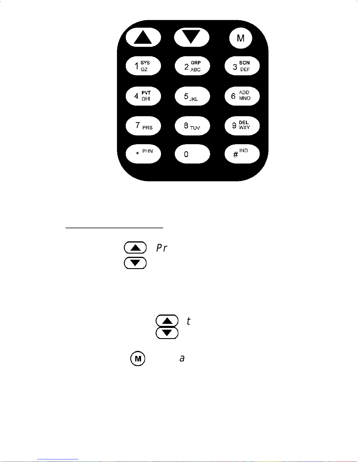
Figure 5 - PRISM HP Keypad (System Model)
Stand ard Fun cti ons
<
>
M
Primary function - changes the system or group/channel (depending on
programming).
Secondary function - used to scroll
through items within a list. Press
<
>
, to scroll in increasing order,
to scroll in decreasing order .
Primary function - accesses the
menu li st. This is a list of additional
features that are not available directly from the keypad. See MENU
for details.
15
Page 16
Secondary function - act ivates a s elected item within a list. After the
menu list is accessed, select a menu
Scan Model
O
A
item from the list via
<
or
>
and activate it with this key. Once
activated,
M
continues its secondary function for activating a selected par ameter set ting until the r adio returns to its normal receive
state.
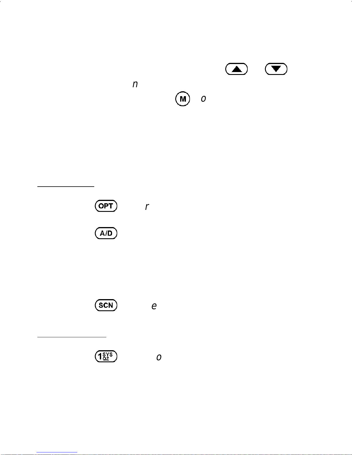
User defined.
Adds or deletes selected groups or
S
System Model
1
channels from the scan list of the currently selected system. See trunked
and conventional scan section for
details.
T oggles scan operation on and off.
Used to directly access systems vi a
the keypad and to access system selection in increasing or decreasing
order , or to select a set (bank) of systems. See SYSTEM/ GROUP/
16
CHANNEL SELECTION for details.
Page 17
2
Used to directly access groups via
the keypad and to access group s election in increasing or decreasing
order, or to select a set (bank) of
groups. See SYSTEM/ GROUP/
CHANNEL SELECTION for details.
3
4
6
9
*
Used to turn scan on and off.
Used to turn private encryption feature on and off.
Adds or deletes selected groups or
channels from the scan list of the currently selected system. See trunked
and conventional scan section for
details. First press recalls current
status. Second press adds or deletes.
Used to place a telephone call
#
through the radio by selecting the
telephone interconnect special call
function. See Telephone Interconnect Calls for details.
Used to call an individual or make an
all-call. See Individual Call for details.
17
Page 18
BUTTO N AND KEYPAD REASSI GNM ENT
Pre-programming the radio using the PC Programming Software permits the reassignment of button and
keypad key functions. The EMERGENCY, OPTION,
CLEAR/MONI TO R and PTT buttons along with the front
panel keypad keys can be reassigned different functions.
For example, the
HOME key, the
O
M
key could be assigned as the
key could be assigned as the
talk-around funct ion key, etc.
The operating procedures that follow assume that the
buttons and keypad keys operate as marked. If they
have been reassigned, Table 1 should be completed to
show the new function(s). Substitute the new assigned
keys when using the operating procedures.
Table 1 - Button and Key Assignm ents
ST ANDARD ASSIGNMENTS REASSIGNMENT
OPTION (Side)
CLEAR/MONITOR
PTT
EMERGENCY
<
>
M
O
A
S
18
Page 19

DISPLAY
The radio display is made up of 3 lines (Figure 6).
Lines 1 and 2 contain eight alphanumeric character
blocks and are used primarily to display system and
group names. Line 1 also displays radio status messages. The 3rd line is used primarily to display radio
status icons. All three lines are used to display menu
options when in the menu mode. If programmed, the
display backlighting will illuminate upon power up when
radio controls are operated.
Figure 6 - P RISM HP Display
19
Page 20

Radio Status Icons
Status icons are indi cators which show the various
operating characteristics of the radio. The icons show
operating modes and condit ions and appear on the third
line of the display as follows:
In trunked mode:
ON - indicates the radio is tr ansmit ting
or receiving a call on t he working channel.
FLAS HING - indicates a call has been
queued.
In conventional mode:
ON - indicates a call is being received.
ON - indicates t he radio is transmit ting.
Note: When operating in a trunked sys-
tem, the radio may be programmed to
automatically transmit (without pressing
PTT) to maintain digital communication
with the site controller. The transmit indicator will turn on whenever the radio is
transmitting.
ON - indi cates the radio is in the special
call select/entry mode (Individual or Telephone Interconnect) .
20
Page 21
ON - indicates the selected group or channel is selected to transmit at high power.
OFF - indicates the selected group or
channel is selected to transmit at low
power.
Auto Power mode automatically adjusts
rad io output power to optimize batter y life.
Indicates batter y voltage is getting low.
Note: When or in conjunction with
LOW BATT
message the radio will no
longer transmit. The radio will automatically power down soon after this condition
exists.
- indicates the EDACS is in the failsoft
mode (if enabled through programming).
ON - indicates the gr oup or channel is enabled to receive encrypted messages.
FLASHING - indicates an encrypted
transmission is being received.
ON - indicates the scan mode is enabled
(rotat es clockwise).
21
Page 22
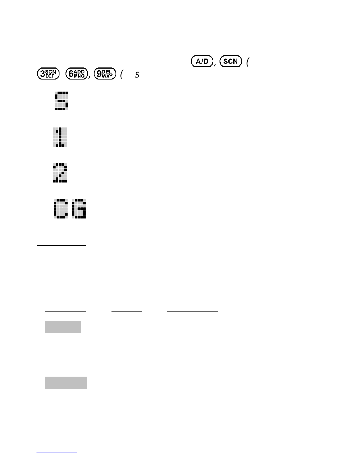
Hidden Status Icons
These icons appear on the system line and are
displayed when the user presses
3, 6, 9
(System ).
- indicates selected group or channel is i n
scan list.
- inicates selected group or channel is priority-one scan channel.
- indicates selected group or channel is
priority-two scan channel.
Indicator for conventional channel with
Channel Guard.
A, S
(Scan) or
Messages
During radio operation, various radio status messages can be displ ayed. The messages are described
below.
Message Name Description
QUEUED
Call Queued - Trunked mode only. Indi-
cates the system has
placed the call in a request
queue.
SY S BUSY
System Busy - Trunked mode only. Indi-
cates the system is busy,
no channe ls are cur rentl y
22
availabl e, the queue is fu ll
Page 23

or an individual call is being attempted to a radio
that is currently transmitting.
DENIED
CC SCAN
WA SCAN
Call Denied - Trunked mode only. Indi-
cates the radio is not
authorized to operate on
the selected system.
Control
Channel
Scan
- Trunked mode only. Indicates the control channel
is lost and the radio has
entered the Control Channel Scan mode to search
for the control channel.
Wide Area
Scan
- Trunked mode only. Indicates the control channel
is lost and radio has ente r e d the Wide Ar e a Scan
TALKARND
LOW BATT
mode to search for a new
system (if enabled
through programming).
Talk-around - Conventional mode only.
Indicates the radio is operating on conventional
channels in talk-around
mode (no repeater).
Low Battery - Battery voltage has
dropped below the point to
where the radio is no
longer able to transmit.
The radio will still be able
23
Page 24

to receive calls until the
battery is discharged beyond the point of operation
upon which the radio will
automatically shutdown.
RXEM ER
TXEME R
VOL = 3 1
Receive
Emergency
- Trunked mode only. Indicates an emergency call is
bein g re ceiv ed. T his message will be flashing on
line two.
T ransmit
Emergency
- Trunked mode only. Indicates an emergency call
has been transmitted.
This message will be
flashing on line two.
Volume Level - Indicates the current vol-
ume level. The volume
level display ranges from
WHC
UNKN OWN
OFF (silent) to 31 (loudest).
Who Has
Called
(trunked
mode
only)
- ON - indicates an individual call has been received,
but no t responded to. Th e
indicator turns OFF if the
individual call m o de is en tered, the system is
changed or the radio is
turned off and back on.
Unknown ID - Trunked mode only. Indi-
cates an individua l call is
24
Page 25

being re ceived by an unknown radio ID.
Error Messages
If either of the following error messages is displayed,
the radio was either programmed incorrectly or needs
servicing:
DSP ERR
DSP ERR
ERR=XXXX
(Power Up only)
UNIVERSAL DEVICE CONNECTOR (UDC)
The Universal Device Connector (UDC) provides
connections for ex ternal acc essories s uch as a headset
or a speaker-micr ophone. When the radio is locked in a
vehicular charger/repeater the UDC provides the audio
and control connections between the radio and the vehicular charger/repeater. The UDC is also used to program and service the radio.
ALER T TONES
The PRISM HP radio also provides audible alert
tones or "beeps" to indicate the various operating conditions. These alert tones can be enabled or disabled
through progr amming.
25
Page 26

Call Originate
A short mid-pit ched alert tone sounds af ter keying the
radio (Push-To-T alk button is pressed). This indicates the
radio has been assigned a working channel or that the
radio is transmitting on a conventional channel and voice
communication may begin immediately.
Call Queu ed (Trunked Mode Onl y)
A high-pitched tone after pressing the PTT button
indicates the system has placed the call request in the
queue. The receiving unit(s) also hear the tones, indicating they will receive a call shortly. I f the the PTT button
is released, the radio will autokey whenever a channel
becomes available (see Autokey) .
Autokey (Trunked Mode Only)
After being placed in queue (see c a lled queued), the
site calls the radio when a channel becomes available.
At this point, the r adio automatically keys the transm itter
(autokey) for a short period to hold the channel. The radio
sounds a mid-pitched tone when it is clear to talk; immediately press the PTT button to keep the ass igned channel.
System Busy (T runked Mo de Only)
Three low-pitched beeps will be heard if: 1) the radio
is keyed when the system is busy, 2) if no channels are
available for sending the message, 3) if the call queue is
full, 4) or if an individual call is being attem pted to a radio
26
Page 27

that is transmitting. Releasing the PTT button and re-keying initiates a new channel request.
Call Deni ed (T run ked Mode Onl y)
If the radio is keyed and a low pitched tone is heard
then the radio is not authorized on the system that has
been selec ted.
Carrier Control Timer
If the programmed time for continuous transmission
is exceeded, five short high-pitched warning tones followed by a long low-pitched tone will be heard. The
transmit ter wi ll shut down shortly after hearing the alert,
interrupting communications. Release and re-key the
PTT button to maintain communications. This will reset
the carrier control timer and turn the transmit ter back on.
Low Battery Warning
A low-pitched tone is heard and comes on indicating that the battery voltage is low. Double tones are
then heard until the PTT or CLEAR button is pressed.
Low Battery Alert (T ransmi t Lo ckou t)
If the radio is keyed and a double tone is heard as
well as is displayed, the battery is dis-
LOW BATT
charged beyond the point where the radio will transmit.
The radio will still be able to receive calls until the bat tery
is discharged beyond the point of operation, after which
27
Page 28

the battery will need to be recharged to resume normal
operation.
Key Press Alert
A short tone or "beep" sounds to indicate a key has
been pressed. A short low-pitched tone indicates the key
is not active in the current mode.
OPERATION
TURNING ON THE RADIO
1. Turn on the radio by rotating the POWER ON-
OFF/VOLUME knob clockwise. A short alert signal
(if enabled through programming) indicates the radio
is ready to use.
2. The display shows the last selected system and
group or a default system and group (depending on
programming).
3. Adjust the POWER ON-OFF/VOLUME knob to the
desired volume level.
4. Select the desired system and group (see system
and group selection section). The display indicates
the current syst em and group names.
5. The radio is now ready t o transmit and r eceive calls.
28
Page 29

NOT E
In the EDACS trunked environment,
CC SCAN
will be displayed if communication
with the system’s control channel cannot be
established. Thi s may occur if, for example, the
radio is out of range of the trunki ng site. It may
be necessary to move to another location or
select another trunking system to re-establish the
control channel link for t runked mode operations.
CC SCAN
is displayed on group line until a
control channel is accessed.
SYSTEM/GR OUP/CHANNEL SELECTION
System Selectio n
Several methods can be used to select a new system.
METHOD 1: From knob: If system selection is pro-
grammed to the SYSTEM/GROUP/
CHANNEL knob, select a system by tur ning the SYSTEM/GROUP/CHANNEL
knob to the desired system number position (1-16). The display registers the new
system name on l ine one.
29
Page 30
NOTE: The radio is supplied with a me-
chanical stop which can, if desired, limit
the number of positions accessed. If the
knob will not access all positions, do not
force it.
METHOD 2: From keypad: If system selection is pro-
METHO D 3:
gramm ed as the primary func tion of
and
<
>
, or
>
, select a system by pressing
to scroll thr ough the system
<
list. The display regist ers the new sy stem
name on line one.
Direct Access: Press
1
to enter the
system select mode. Press the numeric
key which is mapped to the desi red system. Press
M
. The radio will m ove to the
se lected sys tem.
Note: I f system selection is programmed
to the SYSTEM/GROUP/CHANNEL
30
knob, d irect access to system s will not be
available. Pressing
<
or
>
will
scroll through different sets of 16 sys tems
eac h (banks) if more than 16 syst ems are
programmed i nto the radio. The systems
within each bank are then selectable via
the SYSTEM/GROUP/CHANNEL knob
as described previously in METHOD 1.
Page 31

Example:
System: 1 = North Group: 1=Group 1
2 = South 2=Group 2
3 = East 3=Group 3
4 = West 4=Group 4
Press
Press
1
4
(South is the c urrent ly selected s yst em).
.
Press
M
.
31
Page 32

Group or Cha nne l Selection
Several methods can be used to se lect a new group
or channel.
METHOD 1: From knob: If group selection is pro-
grammed to the SYSTEM/GROUP/
CHANNEL knob, select a group by turning
the SYST EM/GROUP/CHANNE L knob to
the desired group number position. The
display registers the new group name on
line two. If the knob is mov ed to a position
greater than the number of programmed
groups, the highest programmed group
will remain selected.
Note: If group selction is programmed to
the SYSTEM/GROUP/CHANNEL knob,
direct access to groups will not be available. Press ing the
<
or
>
will scroll
through different sets of 16 groups each
(banks) if more than 16 groups are programmed into the radio. The groups within
each bank are then selectable via the
SYSTEM/GROUP/CHANNEL knob as
described in M ETHOD 1.
METHOD 2: From keypad: If group selection is pro-
gramm ed as the primary func tion of
and
>
select a group by pressing
<
<
list. The display registers the new group
name on line two.
32
or
>
to scroll through the group
Page 33

METHO D 3:
Direct Access: Press
2
to enter the
group select mode. Press the numeric key
which is mapped to the desired group.
Press
M
. The radio will move to the se-
lected group.
Example:
System: 1 = North Group: 1=Group 1
2 = South 2=Group 2
3 = East 3=Group 3
4 = West 4=Group 4
Press
2
(North is the currently selected group).
Press
4
.
33
Page 34

Press
M
.
TRUNKED MODE OPERATION
Digital trunking provides fast communication access
at all times, even during busy hours. In this mode the
operator selects a communications system and group
and the audio communication or working channel (WC)
is allocated through digital signalling with the site.
Receiving A Group Call
1. Turn on the radio by rotating the POWER ON-
OFF/VOLUME knob clockwise. A short alert signal
(if enabled through programming) indicates the radio
is ready to use.
2. GROUP CALL - When the radio receives a group
call, it unmutes on the assigned working channel and
comes on. Line one shows GR followed by the
logical ID number (if received) of the unit sending the
message, or the associated name if the ID number
is found in the individual call list.
34
Page 35

3. The Prism HP stores the initiating radio ID’s of the
last 10 group c alls received on the selected c hannel.
To access this list press the
#
key twice.
The initiating radio ID of the last group call received
is shown on line one of the display. Use the
>
to
view the radio ID’s of other radios that initiated group
calls. Pressing the
M
key will display the time
elapsed since that call was received.
Pressing PTT will initiate an individual call to the
displayed radio ID. T urning the radio off will clear this
list.
Note: The list described above also functions to
store previous individual calls received. See “Indi-
vidu al Call s ” section for details.
35
Page 36

Sending A Group Call
1. T urn on the radio and set the POWER ON-OFF/VOLUME knob to the desired volume level. Select the
desired system and group.
2. Press and hold the PTT button. The radio will display
the system and group names and perform the
necessary signalling required to obtain a communication channel.
3.
When the working channel is assigned, and
are displayed and a short mid-pitch tone sounds
(if programmed) i ndicating communication can begin.
NOTE
If two or more tones, or a high pitched tone is heard,
the system may be busy and the call request has
been placed in queue or t he request has been denied
for some reason. Refer to the ALERT TONES section
for more details.
4. Hold the radio approximately three inches from the
mouth and speak in a normal voice into the microphone (located upper-left of speaker grille).
5. Release the PTT button when the transmission is
comp lete and listen for a reply.
36
Page 37

Conventional Failsoft
In the unli kely event of a failure o f the EDACS System, communications may take place in conventional
failsoft mode. The radio will be automatically directed to
a commun ications channel set up for this purpose. During this mode of operation, " CO NV FS" will be displayed
in the alphanumeric display . An increase in activity on the
channel during conventional failsoft operation may be
noticed, so be caref ul not to transm it unti l the channel is
clear .
Operation during conventional failsoft will be the
same as operation on a conventional system, except that
it will not be possible to select a communications channel, or use emergency and special call. When trunking
is restored, the radio will automatically be returned to
normal operation.
NOTE
Emergency and Special Call are not operational during conventional failsoft. Also, the GROUP will not
operate.
Emergency Operati o n
The radio’s ability to declare an emergency, clear an
emergency , remain locked on an emergency system and
group, and the em ergency audio and d isplay freeze can
each be enabled or disabled through programming.
When an emergency is declared scanning will stop and
restart s only after the emergency has been cleared.
37
Page 38

Receiving An Emergen cy Call
When receiving an emergency call on the selected
group and system , an alert beep is heard and comes
on. The message flashes in the display on
*RXEMER*
line two until the emergency condition is cleared.
Declaring An Emergency Call
To send an emergency call to selected system and
group (or on an optionally preprogrammed group), proceed as follows:
1. Press and hold the red EMERG ENCY but ton that is
on top of the r adio in front of the antenna f or approximately one second (this time is programmable and
therefore could be longer or shorter; check with the
system administrator). The radio will transmit an
emergency call request with the radio ID until an
emergency channel assignment is received.
2. When the working channel assignment is received,
the radio sounds a single beep indicating the radio
has auto keyed (see Auto Key) and is ready for
voice transmission.
*TXEMER*
flashes on line two in the display until
the emergency is cleared.
3. Press PTT and speak into the microphone in a
normal voice. and momentarily turns on.
4. Release PTT when the transmission is complete.
38
Page 39

5. To clear the emergency first press and hold the
CLEAR/MONITOR button. While continuing to hold
the CLEAR/MONITOR button, press the EMERGENCY button.
SCANNING TRUNKED GRO UPS
Groups which have been previously added to the
scan list on a per system basis may be scanned. Each
system ’s group scan list is retained in memory when th e
radio is turned off or when the battery pack is removed.
The following procedures out l ine scan operat ions for
trunked groups. See the conventional mode operating
procedures for specific procedures on conventional
channel scanning.
Turning Scan On and Off
1.
Toggle scan operation on by pressing
or
3
(System ). icon rotates clock w ise to indi-
cate radio is scanning.
2.
Toggle scan operation off by again pressing
3
If the rad io scans to a group other than t he select e d
-
. will disappear.
group then receives a call on the selected group, the
A
(Scan)
A
or
radio will swi tch t o the selected group since it has
priority.
39
Page 40

The radio will continue scanning if a new group is
-
selected when scan is on.
Pressing the PTT butt on when sc an is on will cause
-
the radio to transmit on the displayed group or to the
currently selected group (depending on programming).
SCAN Radio
Adding Groups to a Scan List
1. Scan must be off to add/delete channels to/from the
scan list. If the scan icon is on, press the
S
key to turn scan off.
2. Select the desired channel using the SYS-
3.
TEM/GROUP/CHANNEL knob and/or the
>
list, pressing
keys. If the select ed channel is currently on t he
A
will display the S status flag.
While the status is displayed, press the
<
A
or
key to
add a group to the scan list. “S” is displayed on line
one.
4.
Press the
A
key a second time to set the group
to Prior ity 2. A “2” is displayed on line one.
5.
Press
A
a third time to set the group t o Priority 1.
A “1” is displayed on line one. The priority level
section sequence only advances the group to the
next high priority level and stops at priority level 1.
40
Page 41

To select a lower priority level, the group must be
deleted from the scan list and then added back to the
scan list. Each new group added to the scan list
starts at the lowest priority . If the priority 1 and Priority
2 groups are already set and a new group is assigned as Priority 1 or Priority 2, the previously
assigned group will change to non-priority scanning.
One of the following messages m ay be moment arily
displayed:
SCAN DIS
FIXED P1
The radio is not programmed to scan.
A Priority 1 group has been pre-pro-
grammed into the radio. A new Priority 1
group cannot be selected.
FIXD LST
A fixed scan list has been pre-programm ed into the radio. It is not possible
to change the list without reprogramming
the radio.
Note: To quickly view multiple group scan status,
press
A
then slowly but consistently rotate the
group knob. Each group status will appear on the
display.
Deleting Groups from a Scan List
1. With scan operation turned off, select the desired
group to delete from the selected trunked system
group scan list.
2.
Press
A
played for a time-out period.
. The current status of the group is di s-
41
Page 42

3.
While the current status is displayed, press
until the group from the scan list is “blank”. The
sequence is “blan k”, “S”, “2” ,“1 ”, “b lank”. Any group
that is not in a trunked system group scan li st will
show a “blank” for the time-out period when it is the
selected channel.
Nuisance Delete
A group can also be deleted from the scan list, if it is
A
not the currently selected group, by pressing
A
key
during scan operation while the radio is displaying the
unwanted group. The group will be deleted from the
system’s group scan list in the same manner as if done
using the steps above. Deletions done in this manner will
not remain deleted if the radio is turned of f and then back
on.
SYSTE M Radio
Addin g Grou p s To A S can L is t
1. With scan operation turned off, select the desired
group to add to the selected trunked system group
scan list.
2.
Press
6
. The current priority st atus of the group
will be displayed in column 1 of line one for a time-out
period (refer to
is not part of the scan list the stat us will be blank.
3.
While the status is displayed, press
group to the scan list. "S" is displayed on line one.
42
Hidden Status Icons). If the group
6
to add the
Page 43

4.
Press
6
a second time to set the group to Priority
2. A "2" is disp layed on line one.
5.
Press
A "1" is displayed on line one. The priority level
selection sequence only advances t he group to next
higher priority level and stops at priority level 1. To
select a lower priority level , the group must be deleted from the scan list and then added back to the
scan list. Each new group added to the scan list
starts at the lowest priority. If the Priority 1 and
Priority 2 groups are a lready s et and a new group is
assigned as Priority 1 or Priority 2, the previously
assigned group will change to non-priority scanning.
One of the following messages m ay be moment arily
displayed:
SCAN DIS
6
The radio is not programmed to scan.
a third time to set the group t o Priority 1.
FIXED P1
A Priority 1 group has been pre-programmed into the radio. A new Priority 1
group cannot be selected.
FIXD LST
A fixed scan list has been pre-programm ed into the radio. It is not possible
to change the list without reprogramming
the radio.
Note: To quickly view multiple group scan status,
press either
6
or the
9
key. Then slowly but
consistently rotate the group knob. Each group
status will appear on the display .
43
Page 44

Deleting Groups From A Scan List
1. With scan operation turned off, select the desired
group to delete from the selected trunked system’s
group scan list.
2.
Press
9
. The current status of the group is di s-
played for a time-out period.
3.
While the status is displayed, press
9
to del ete
the group from the scan list. " S", "2" or "1" turns off.
Any group t hat is not in a trunk ed system group scan
list will show a "blank" for the time out period when
it is the selected channel.
Nuisance Delete
A group can also be deleted from the scan list, if it is
not the currently selected group, by pressing
9
key
during scan operation while the radio is displaying the
unwanted group. The group will be deleted from the
system’s group scan list in the same manner as if done
using the steps above. Deletions done in this manner will
not remain deleted if the radio is turned of f and then back
on.
SCANNING TRUNKED SYSTEM S
Wide Area System Scan ning
The PRISM HP radio may be programmed for wide
area system scan operation for roaming across mobile
systems. Upon the loss of the currently selected system’s control channel, radios may be programmed to
44
Page 45

automatically scan the control channels of other systems. If a new control channel is found, the radio will
switch to the new system and sound an alert tone.
Priority System Scan
The radio may also be programmed for priority system scan. A pr iority system may be assigned among t he
systems programmed into the radio. Radios programmed in this manner will check for the priority trunked
system’s control channel at a programmable rate ranging
from 1 to 16 minutes. This priority scan timer is reset each
time the PTT button is pressed or when a call is received.
If the priority system control channel is found, the radio
will automatically sw itch to the priority system .
ProSo und
The radio may be pr ogrammed f or ProSound sy stem
scan operation for multi-site applications. ProSound
scanning is an enhanced replacement for wide area
system scanning. This algorithm insures that the radio
continually receives high quality audio. When the selected system degrades to a pre-programmed level, the
radio changes to the new system and sounds a tone.
Should the control channel be lost completely, the radio
will scan the adjacent systems until a suitable one is
found.
45
Page 46

INDIVI DUAL CALLS
Receiving An d Respond ing To An Indi vid u al Cal l
(Trunked Mode Only)
When the radio receives an individual call (a call
directed only to the user’s radio), it unmutes on the
assigned working c hannel and turns on . The first line
on the display shows the l ogical ID number of the unit
sending the message, or the associated name if the ID
number is found in the individual call list. The radio can
be programmed to ring when an individual call is received. If enabled, the ring begins five seconds after the
caller unkeys and will continue until the PTT button, the
CLEAR/MONITOR button or the individual call mode is
entered.
NOTE
The volume of the ring is adjustable through the
volume control levels.
If a response is made by pressing the PTT to the call
prior to the programmed call-back time-out, the call will
automatically be directed to the originating unit. If a
response is not made before the call-back time-out, the
radio will return to normal receive display, and
*WHC*
will appear on the first line of the LCD.
To respond after the call-back time-out, press the
#
key. The radio’s display will show the callers ID on
the first li ne and WHCI=1 on the second line. Pressing
the PTT button at this point will initiate an individual call
back to the original caller .
46
Page 47

The radio stores the ID’s of the last 10 callers in the
Calls Received List as shown. Individual calls are stored
in the top half of the list (1-10) and Group calls are st ored
in the bottom half of the list (1-10). The most recent call
is stored in position 1, the second most recent call is
stored in position 2 etc.
To access this list, press the
< >
M
key will display the time elapsed since the call was
keys to scroll through the list. Pressi ng the
received. A fter pr essing
is as follows
#
#
key twice. Use t h e
an example of the display
47
Page 48

Pressing PTT will initiate an individual call to the
displayed logical ID. T urning the radio off and on will clear
this list.
Send in g An In d ividual Call ( T runked Mode O nl y )
Pre-Stored Individual Calls
The following procedures describes how to initiate
and complete a pre-stored individual call.
System Model
1. To select a pre-stored individual phone number,
enter the individual call mode using the
#
key.
turns on. Then scroll through the list of stored
numbers using the
<
or
>
key.
2. Press the PTT button; when the radio is clear to
transmit, turns on, turns off and the channel
access tone sounds. Line one shows the called
individual’s name if found in the list of stored individuals or ID followed by the logical ID number of the
unit being called. The message displays on
*INDV*
line two.
Scan Model
1. To select a pre-stored individual number, enter the
menu mode by using the
mode list using the
48
<
M
or
key. Scroll through t he
>
key to .
*INDV*
Page 49

Press
M
. turns on. Scroll through the list of
stored phone numbers using the
<
until the desired number is displayed. Press
or
>
M
key
.
2. Press the PTT button; when the radio is clear to
transmit turns on, turns off and the channel
access tone sounds. Line one shows the called
individual’s name if found in the list of stored phone
numbers. The message displays on line
*INDV*
two.
Direct Dialing of Individ ual Calls (Syst em Model
only)
The following procedures describes how to initiate
and complete a direct dialed individual call.
1. If the individual call ID is not stored in the pre-st ored
list of call ID’s but the individual unit ID is known, it
can be entered directly from the keypad.
Note: The ID of the last individual call made can be
recalled by pressing
#
then the OPTION button.
2. Press the PTT button to transmit. turns on,
turns off and the channel access tone sounds. Line
one shows the called individual’s ID followed by the
logical ID number of the unit being c alled. The mes sage displays on line two. Proceed talking
*INDV*
into the microphone.
49
Page 50

Call St orage Lists
There are two lists available for call storage in the
PRISM HP radio, the
calls received list (1 - 10) and the
personality list (1 - 99 as defined by the user). When the
individual call mode is entered by pressing
#
, the
calls received list is available. The user can toggle to the
personality list by selecting any index other than 0 or
toggle between the two lists by pr essing the
wrap is enabled, the
calls received list wraps on itself and
#
key. If
not into the other list.
The saved call list shows all ten storage locations. If
no calls have been received, the saved call list will be
empty and the pre-stored list will be available upon
entering the individual call mode.
When in the saved call list, pressing the
toggles the time stamp on and off. The time stamp
indicates how long ago the call was received. When in
50
M
key
Page 51

the pre-stored list pressing the
M
key toggles the
Logical IDentificat ion (LID) on and off.
TELEPHO NE INT ERCO NNECT CALL S
Receiving A Tel epho n e Intercon n ect Cal l (T runked
Mode Only)
When the radio receives a telephone interconnect call
(a call directed only to the user’s radio), it unmutes on
the assigned working channel and turns on . The first
line displays .The second line displays
*INDV*
. Proceed with the call.
*PHONE*
Send ing A T el ep ho ne In terco nnect Cal l (T ru nked
Mode Only)
Pre-Stored Number
Use the following procedures t o initiate and com plete
a Telephone Interconnect call:
1. (System Model) T o select a previously stored phone
number, press
>
keys to scroll through the list of stored num-
*
. turns on. Use the
<
,
bers.
(Scan Model) To select a previously stored phone
number, press
select the menu option "PHN CALL". Press the
key again then use the
through the list of prestored numbers .
M
. Use the
<, >
<, >
keys to scroll
keys to
M
51
Page 52

2. Press and release the PTT button. When the radio
is clear to transmit, turns on, turns off and
the channel access tone sounds. Line one shows
the accompanying name selected from the list of
stored numbers. The message di splays
*PHONE*
on line two. The radio then automatically transmits
the programmed number stored in the special call
queue.
3. A telephone ring will be heard from the speaker.
When someone answers the phone, press the PTT
button and speak into the microphone. Release the
PTT button to listen to the callee. Unsuccessful
interconnect si gnalling returns the radio to the normal receive mode and the number remains displayed until the special call is cleared or the time-out
expires or another group or system is selected.
Terminate a call by pressing the CLEAR/MONIT O R
button.
NOTE
In half-duplex mode, only one person may talk at
a time. The radio PTT button needs to be pressed
in order to communicate to the individual called
and released for t he individual called to be heard.
4. To terminate the call, momentarily press the
CLEAR/MONITOR button.
52
Page 53

Direct Dialing of Phone Call s (System Mo del onl y)
*PHONE*
1. If the phone number is not stored in the pre-stored
list of phone numbers, but the phone number is
known, it can be entered directly from the keypad.
Start by pressing the
*
. Then enter the required
number from the keypad.
Note: The last number entered directly can be re-
called by first pressing
*
then the OPTION but-
ton.
2. Press the PTT button: t he radio perf orms the neces sary signalling to obtain a communication channel .
When the signalling is complete and the radio is clear
to transmit, turns on, turns off and the
channel access tone sounds. Line one shows the
called phone number. The message displays on line two. The radio then automatically transmits the dialed number.
3. A telephone ring can be heard from the speaker.
When someone answers the phone, press the PTT
button and speak into the microphone. Release the
PTT button to listen to the individual called. Unsuccessful interconnect signalling returns the radio to
the normal receive mode and the number remains
displayed until the special call is cleared or the
time-out expires or another group or system is selected. Terminate a call by pressing the
CLEAR/MONITOR button.
53
Page 54

NOTE
In half-duplex mode, only one person may talk at
a time. The radio PTT button needs to be pressed
in order to communicate to the individual called
and released for t he individual called to be heard.
4. To terminate the call, momentarily press the
CLEAR/MONITOR button.
DTMF Overdial / C onventional M ode Telephone
Interconnect
Once the radio has established a connection to the
public telephone system, it may be necessary to "overdial" more digits to access banking services, answering
machines, credit card calls or other types of systems that
require DTMF (Dual-Tone Multi-Frequency) access digits.
Overdial operation can also be used to initiate a
telephone interconnect call via DTMF signalling if a dial
tone has already been accessed on the system. This is
the method that is used for making a telephone interc onnect call while operating in the conventional mode but
will also function in trunked mode if a dial tone is directly
accessible.
T elephone numbers and other number sequences for
overdialing can be stored in the phone list when programming the radio. These numbers are accessed by pressing
M
, then following the selection mode rules.
54
Page 55

The following steps are required to dial these numbers :
SCAN Radio:
1. Follow the procedure in Sending A Te lephone Interconnect Call (Trunked Mode On ly) to establish
a connection to the telephone sy stem or cons ult th e
system administrator for the procedure to access a
dial tone on the trunked or conventional system.
2. Overdial numbers are transmitted by entering the
phone mode using the
Press
M
to enter the overdial select/entry mode
M
button.
and follow the selection mode rules to call up a
stored number from the phone list. turns on.
Press PTT to send the overdial sequence once. If
the number needs to be transm itted again it must be
selected or entered agai n (this prevents unwanted
numbers from being sent the next time the PTT
button is pressed during the call).
This overd ial select/entr y mode remains active until
the call is dropped, cleared, or
M
is pressed. The
overdial select/entr y mode can be re-entered if the
call is still active by pressing
M
.
55
Page 56

System Radio:
The following steps are required to dial these num-
bers:
1. Follow the procedure in Sending A Te lephone In-
terconnect Call (Trunked Mode On ly) to establish
a connection to the telephone sy stem or cons ult th e
system administrator for the procedure to access a
dial tone on the trunked or conventional system.
2. Overdial numbers are transmitted using either
method as follows:
METHOD 1: Press and hold PTT while entering the
overdial number sequence from the keypad. This m ethod sends DTMF tones dur ing individual, telephone interconnect.,
trunked group or conventional channel
calls. Anyti me the PTT button is pressed
and h eld, t he keypad is enabled for DTMF
entry.
METHO D 2:
Press
*
to enter the overdial select/entry mode and follow the selection mode
rules to call up a stored number from the
phone list or to direct enter the overdial
digits. turns on. Press PTT to send the
overdial sequence once. If the number
needs to be transmitted again it must be
selected or entered again (this prevents
unwanted numbers from being sent the
56
Page 57

next time the PTT button is pressed during
NO ENTRY
the call).
This overdial select/entry mode remains
active until the c all is dropped, cleared, or
M
is pressed. The overdial select/ entry
mode can be re-entered if the call is still
active by press ing
*
.
PROGRAMMABLE ENTRIES
Prestoring Individual and Telephone Interconnect
Calls from the Keypad (System Model only)
Individual Call ID numbers, telephone numbers and
other number sequences for overdialing are stored in the
special calls lists when programming the rad io. The first
ten entry locations of these lists can be changed by the
radio operator . The keypad is used when adding, changing and storing numbers in these entry locations.
of the first ten entries of a special call list:
1.
2.
Use the following procedure to store a number in one
Press
#
or
*
to enter the individual call list or
the phone call list. turns on.
Scroll through the list using the
<
or
>
until
one of the first ten entries is reached.
is displayed if the location is empty.
57
Page 58

3. Enter the desired number . If necessary, a pause can
be entered by pressing and holding 0-9,
#
until an underscore appears in the display
*
, or
(telephone interconnect only). The individual call list
entries will accept up to 5 digits. The phone call list
entries accept a combination of up to 31 digi ts and
pauses.
4.
Press and hold
M
until the display changes indi-
cating that the number has been stored.
5. Repeat the steps above if the number stored in an
entry location needs to be changed.
STATUS/ME SSAG E OP ERATION
Status operation permits the transmi ssion of a preprogrammed status conditi on to the EDACS site. Message operation permits the transmission of a pre-programmed mess age text to an EDACS site.
STATUS OPERATION
To send a status condition, press the
lowed by
<
or
>
key to select the pre-programmed
M
key fol-
status. STA TUS and 0 through 9 pre-program med status
selections are available from the menu. If STATUS is
selected you need to enter the number of the status
message you intend to transmit. If no s tatus has been
programmed for the selected number key, the radio will
display "NO ENTRY". A valid sel ection wi ll permit the
status text to appear in the display for a pre-programmed
time. A fter t he tim e-out expires or the
pressed (the
M
key will override the time-out period),
58
M
key has been
Page 59

the status is selected and will be transmitted to the site
or stored in the radio memory where it can be polled by
the site at a future time. Status messages can also be
programmed for single key operation so that a single
press of a key assigned to a status message automatically transmits that message. If the s ite does not receive
the status properly, the radio will sound a low pitched
tone.
The status selection can also be canceled by press-
ing the CLEAR button prior to the time-out period.
To view the currently selected stat us after it has been
M
transmitted, press the
key and then the
<
key to
ramp to STS, re-press the
M
key again and then the
CLEAR button prior to the time-out period. If the status
was not sent succes sfully to the site, t he text assoc iated
with the status w ill flash in the display.
MESSAG E OPE RATION
Message operation is perfor med in the same manner
as status operation in previous paragraph.
DYNAMIC REGROUP OPERATIO N
Dynamic group operation permits multiple talk groups
(up to eight) to be added to a radio via the system
manager. The radio must be pre-programmed to respond to regrouping. Dynamic regrouping will not be
activated in a radio until an activation message is sent
by the system manager. Each radio that receives and
acknowledges the regrouping instructions is successfully regrouped.
59
Page 60

Pressing and holding the CLEAR/MONITOR button
for 2.5 seconds toggles the user into and out of the
dynamic regroup groupset. A double beep will sound for
entry or exit. The display will indicate "REGRP_0x"
where "x" is a digi t of 1 t o 8 indicating the group when
dynamic regroup has been enabled by the user. If the
radio is in dynamic regroup and the user select s a group
that has not been regrouped, the display will show "NO
ENTRY". The radio will be prevented from transmitting
and receiving calls i n this condition except for scanned
groups.
Emergency Operati o n
If the pre-programmed groupset on the currently selected system contains an EMER/HOME group and the
radio is in dynamic regroup, the radio will declare the
emergency on the currently selected dynamic group
group.
MACRO KEY OPE R ATION
Macro key operation permits the user to accomplish
a series of key s trok es with a single "m acro" k ey stroke.
Up to ten (10) macro keys can be defined, each capable
of executing up to twenty (20) key strok es, t o any push button input (i.e., keypad keys, OPTION button, etc.).
Each macro key can be pre-programmed to activate
when pressed or when released.
A macro key may also be pre-programmed to change
the key stroke sequence the next time the macro key is
activated.
60
Page 61

For detail operation and assignment of macro keys,
contact your communi cations supervisor or administrator.
EDACS CONVENT IONAL P1 SCAN
This feature perm its the radio user to scan a pre-programmed convent ional system and c hannel as a Priority
1 (P1) channel while the radio is selected for EDACS
trunked system. If activity is detected on the conventional
P1 channel, the radio will unmute and remain on this
conventional channel for the programmable hang time.
The radio must be pre-programmed to designate a
key for P1 scan on/off operation.
MENU
The menu function accesses features that are not
available directly from the key pad. The or der and ac tual
menu items available is configurable through programming. Upon rad io power up, the menu item that is at the
top of the menu li st will always be displayed first. Subsequent access to the menu function will return the last
menu item that was shown in the display and cursor
position. To enter the menu mode, press
M
.
61
Page 62

Upon entering the menu selection mode, Menu op-
tions will appear on the display i.e.
Note:
, , are still viewable in MENU mode.
is available unless the cursor is on row 3.
The radio will continue to receive and transmit nor-
mally while in the menu function.
To scroll through the menu options use the
>
keys. When the required menu item has been found
align the cursor with the option then press
M
<
, or
to select
it. The menu item’s parameter setting shown in the
display can now be changed by using
<
, or
>
to
scroll through the list of parameter values. Once the
desired setting is reached press
M
to store the value
and return the menu option selection level. For menu
items that display radi o information, pressing
>
will scroll through a list of informational displays.
The possible menu items are listed in Table 1.
62
<
, or
Page 63

An example of the menu item selection process and
menu item parameter change is detailed below for the
backlight menu item.
PRESS:
M
The menu mode is entered.
PRESS: ,
PRESS:
<
M
or
>
. until the disp lay shows:
The backlight menu item is activated.
Line one shows the active menu item and its current
parameter setting. Line two shows the currently selecte d
system or group name.
The menu item’s parameter setting shown in the
display can now be changed by using
Once the desired setting is reached press
<
M
, or
>
to store
the value and return the menu option selection level.
.
63
Page 64

For menu items that display radio information press -
ing
<
,or
>
will scroll through a list of informational
displays. The menu items are listed Table 2.
NOTE
The TX POWER menu item, when selected, toggles
LO/HI/AUTO power for trunked systems or LO/HI
power for conventional s ystems. It does not use
or
>
to scroll nor an additional press of the
button.
<
M
64
Page 65

Table 2 - Menu Item Informat io n
FEATURE DISPLA Y PARAMETER
SETTING
Keypad Lock Menu item:
KEY LOCK
Once sel ected:
LOCKED
Backlight Adj ust Menu item:
BCK LIGHT
Once sel ected:
BCKL=
Contra st Adjust Menu item:
CONTRAST
Once sel ected:
CNTRST=
T ra nsm it Powe r
Select
Menu item:
TX POWER
Once sel ected:
POWER=
Locked
Unlocked
OFF-ON Selec ts the light le vel for
1, 2, 3, 4 Selects the disp lay
HI, LO
AUTO-TRNK
COMMENT
Locks the keypad . To
unlo ck; press and release
“M” then within 1 second
press the optio n button.
(NOTE: this sequence is
also a shor t cut to locking
the keypad.)
backlighting.
cont rast level .
Selects:
radio outp ut
power mode
Radio Revision
Information
Toggle Scan
On/Off
Toggle Private
Mode
Display current
AEGIS Encrypt ion
Key
Display Current
Home Gro up/
Channel
Select Desired
System
Add Group/
Channel to Scan
List
Menu item:
REVISION
SCAN ON/OFF Toggles Scan operation
PRIVATE ON/OFF Toggles AEGIS private
DISP KEY Informational
HOME N/A Selects Hom e
SYS SEL N/A Refer to the Tab le of
SCAN ADD N/A Adds to Scan List.
Informational
displays only (see
radio); no user
selectable settings.
displays only (see
radio); no user
selectable settings
Selects the information
display to view.*
On/Off.
mode ON/ Off.
Displaces current
encryption key.
Group/Chann el
Conten ts for SYSTEM/
GROUP/ CHANNEL
SELECT ION.
65
Page 66

Delete
Group/Channel
From Scan List
SCAN DEL N/A Deletes from Scan List.
Add/Delete Scan
List
Select Telephone
Numbers From
Phone List
Data Operation NO DATA ON/OFF Trunked Only. Toggles
Conv P1 Scan ECP1SCAN ON/OFF Trunked Only. Toggles
Select Individual
Call from IC List
Select Group GRP SEL N/A Trunk ed On ly. Refer to the
Talkaround TALKARND ON/OFF Conventional Only.
SCAN A/D N/A Add, deletes from Scan
List.
PHN CALL N/A T runk ed Only. Refer to the
Table of Contents for
TELEPHONE
INTERCONNECT CALLS.
Data operation On/Off
Conv P1 Scan On./Off
IND CALL N/A Trunked Only. Refer to the
Table of Contents for
TELEPHONE
INTERCONNECT CALLS.
Table of Contents for
SYSTEM/GROUP/
CHANNEL SELECTION.
Toggles talkaround feature
On/Off
Select Channel CHN SEL N/A Conventional Only. Table
of Contents for
SYSTEM/GROUP/
CHANNEL SELECTION
ProFeatures Menu item:
PROFEAT
SERIAL_ROM_#
FEATDATA_2
TRKSYS#
Informational
displays only (see
radio); no user
selectable settings
Indi cates current features
programme d into the ra dio
as well as certain
information required to add
features to the radio (refer
to Table of Contents for
ProFeatures).
66
Page 67

*Information Display
PRS - NAME
XXXXXXXX
ERICSSON
(C) - 1995
FLSH - VER
hklr01A_
DSP_ _RAM
hklr01a_
Personality Name
Copyright
FLASH Software
r - released, 01A - revision state
DSP Software
hk1 - AEGIS unencrypted
hk2 - AEGIS w/VGE encryption
hk3 - AEGIS w/DES encryption
r - released, 01A - revision state
PROF EATURE
ProFeature is available through the menu function
and, if programmed, appears in the menu as “PRO-
FEAT.” The PROFEA T menu also provides access to the
radio ProFeature data. This data indicates current features programmed into the radio as well as information
required to add features to the radio.
Once the feature has been accessed, all normal
menu functions work. The user can scroll up or down
through all of the entries.
Pro Features provide the ability to view, in the order
displayed, the following:
••
Serial number ROM data - serial number of the ROM
••
Feature encryption data stream - used to enable
features
••
Number Fields - defines limits
••
Features enabled - displays bit fields of enabled
features
67
Page 68

Serial Number ROM (12 Hex Digits)
Example:
When the user wants to enable a feature in his ra dio,
he will need to call Ericsson Inc. They will ask for the
ROM serial number . The serial number shown here is for
example only.
Feature Encrypt ion Data Stream
Example:
These data stream s def ine the f eatur es t he user has
enabled in his radio and are required by Er icsson Inc. to
enable other features. The data streams shown here are
for example only. No te: There are three displays : FEATDATA1, FEATDATA2, FEATDATA3. All three are required.
68
Page 69

Number Field s
Example:
These number fields show the set limits of the of the
user’s radio as:
••
SYSGRP# -XXX - Maximum number of system/groups combinat ion available
••
TRKSYS#_XXX - EDACS maximum trunked system
limit
••
CNVCHN#_XXX - Maximum number of conventional channels available
The user needs to know t he limits of his radio bef ore
attempting to enable other features. The numbers shown
here are for example only.
69
Page 70

Features Enab led
These numbers indicate which features are enabled.
Example:
The following numbers indicate features available in
the user’s radio.
Bit Fields Possible Features
01 Conventional Priority Scan
04 Trunked Group Scan
05 Priority System Scan
06 Wide Area Scan/ProSound
07 Dynamic Regroup
08 EDACS Emergency
10
Conventional Emergency
12 AEGIS
13 VGE
14 DES
15 VGS or User Specific Encryption
16 DATA
17 EDACS Status/ Mes sage
70
Page 71

AEGIS OPERATION
VOICE MODES
Aegis programmed systems have three (3) different
voice modes: clear (analog), digital and private (encrypted). The voice modes are programmed on a pergroup basis within each trunked system and on a perchannel basis within each conventional system.
Mode 1: Clear Modes
The Aegis clear mode is a voice mode i n which the
radio transmits and receives only clear (analog) voice
signals. These analog signals are non-digitized and nonencrypted. Clear mode transmissions can be easily
monitored by unauthorized persons. Groups or channels
programmed for clear operation cannot transmit or receive Aegis digital or private messages.
Mode 2: Aegis Digital Mo d e
The Aegis digital mode allows the radio to transmit
and receive digitized voice signals. Aegis digital signals
provide improved weak signal performance and cannot
be easily monitored with a standard receiver. Groups and
channels programmed for Aegis digital operation transmit only digital signals. Private (encrypted) calls cannot
be received or transmit ted when the r adio is in the Aegis
digital mode because the radio does not know the cryptographic key used. Message trunked group calls and
individual calls are answered back in the mode which
they are were received assuming t he call or hang time is
still active. Individual phone, all, and emergency calls are
71
Page 72

transmitted clear if the digital mode is disabled or inoperative.
1. If receiving an analog message trunked call, the
radio responds in the analog mode during the hang
time on the working channel.
2. If receiving an analog I-Call, the radio responds in
the analog mode during the hang time.
3.
When using the feature to respond to an
*WHC*
I-Call (after the hang time has expired), the call is
transmitted in t he mode defined by the sy stem mode
as programmed for the curr ent system if the ID being
called is not in the I-Call list. If the ID is in the I-Call
list, then the call is transmitted as defined by the
I-Ca ll mode programmed in the list for that ID.
DTMF
The overdial DTMF tones are not available whil e in
the Aeg is Digital Mode.
Mode 3: Aeg is Pri vate Mod es
The Aegis private modes allow the radio to transmit
encrypted messages and receive clear or private transmissions. The radio transmits private if the group/channel is programmed for private operation and forced operation is pre-programmed. If autoselect operation is
pre-programmed and the radio is in the private mode, the
radio transmits in the mode of the received call if the hang
time is active. If no hang time is active, the radio transmits
private.
72
Page 73

Cryptographic k eys are transfer red to the radio using
a cryptographic Keyloader. Up to seven (7) different
cryptographic keys, numbered 1-7, can be transferred
from a Keyl oader and stored in the radio. An individual
key is automatically selected on a per-group/channel
basis according to the radio programming. Groups and
channels within the Aegis system can be programmed
for keys 1-7 (DES and VGE). Up to 8 banks of 7 keys
can be stored for Aegis (DES and VGE) systems. The
bank is specified per system.
DES rad ios require a DES Keyloader (Opt ion V4025
with software version 3.N or later). VGE radios require
VGE Keyloader (Option V4028 with software version 2.N
or later).
When operating on a group or channel programmed
for private mode, al l transmissions are pr ivate t ransm issions and the radio receives clear and private signals.
The status icon display turns on when the private
mode is enabled. If the selected group or channel is
programmed for aut oselect c apability, the mode may be
toggled between private and clear with the
M
key , then
following the selection mode rules. Radios programm ed
for forced pr iv ate operation do not allow a change of the
transmit mode.
Transferrin g Keys Into the Radio
The following procedure outlines basic key t ransfer-
ring steps.
1. Turn the radio off.
73
Page 74

2. Plug the modular connector of the Keyloader cable
into the Keyloader modular jack.
3. Connect the Keyloader cable to the UDC on the
radio.
4. Press the PWR butt on on the Keyloader and wait fo r
the Keyloader to display “MASTER MODE ”.
5. Press the TRN button on the Keyloader. If necessary , select a different cr yptographic key to be transferred into the radio.
6. Turn the radio on. The top line on the radio display
will read “KEY LOAD” and the second line will read
“BANK = N” where N=keybank number. Press the
<
or
>
button to select the keybank. A beep
will indicate that the keyloader is connected.
7. Press the EXE button on the Keyloader to transfer
the key. The Keyloader will display “GOOD 1.x
TRANSFER” where “x” is the select ed cryptographic
key number .
8. Disconnect the cable from t he radio UDC. The radio
will change to the selected group or channel as
indicated in the display .
Displaying The Currently Used Cryptographic Key
Number
To display the cryptographic key currently in use for
either the system encry ption key (for special call such as
74
Page 75

individual, phone, all, agency or fleet) or the group/c hannel key (for group or conventional calls), perform the
following procedure:
1.
2.
3.
Press the
Use the
Then use the
M
<
button .
or
>
<
or
displaying the system key or the group/channel key.
System Encryption Key
button to select “ DISP KEY”.
>
button t o toggle between
Group/Channel Encryption Key
75
Page 76

Key Zero
All cryptographic keys can be zeroed (erased from
radio memory) by pressing the MONITOR/CLEAR button and while s til l pressi ng thi s button, press and hold
the OPTION button. Press bot h buttons for 2 seconds. A
series of beeps will begins at the start of the 2 second
period and then switch t o a solid tone after the keys have
been zeroed. The display will indicate “KEY ZERO.”
If the cryptographic key(s) are zeroed, one or more
keys must be transferred from the Keyloader into the
radio before private communicat ions may continue.
Private Operation
Receiving An En crypted Call
When receiving, the radio automatically s witches b etween clear or private operation. If the transmission
being received is an encrypted transmission, it will be
decrypted, the icon will turn on, the receiver will
unsquelch and the message will be heard in the speaker.
For this to occur, the select ed group or channel m ust be
programmed for pri vate operation and the correct cryptographic key must be loaded into the radio.
Transmitting An Encrypted Cal l
1. Select the desired group or channel.
2.
Place the radio in private mode by pressing the
key, then follow the selection mode rules. On a
System radio, the
76
4
M
key can be used to toggle
Page 77

the private mode on/off . When private mode is enabled, the icon will be on.
If the last state of the radio was pri vate mode, the
private mode will be enabled on power up. Also the
private mode will be enabled if forced operation has
been programmed in the radio.
If a group or channel is not programmed for private
mode operation, “PVT DIS” will be displayed if attempt is made to enable private trans mit mode. It is
not possible to operate on this group/channel in
private mode.
If the rad io does not have the correct enc ryption key
loaded, “NO KEY#” will be displayed and the call will
not be transmitted.
3. Continue with standard transmission procedures. A
private mode access tone will be heard when the
PTT button is pressed.
Scanned G rou p Calls
Receiving a scanned group call is the same as receiving a selected group call. During the scan hang time, if
the radio was programmed for autoselect , it will transmit
back in the same mode it received the call. For example,
if a clear group is entered in the scan list, it will only
receive clear calls. I f the same group was availabl e in
private and entered in the scan list, it can receive clear
and private calls, provided autoselect was programmed
in the radio. The user can select transmitting on the
77
Page 78

scanned or selected group. If a group is entered in the
scan list more than once and in different modes (clear,
digital, private), only the first occurrence of the group will
be used.
Table 3 - Transmit/Receive Mode Compatibility For
AEGIS Oper ation
GROUP/CHANNEL
PROGRAMMING
(TRANSMIT)
CLEAR Y es No No
DIGITAL Y es Y es No
PRIV ATE Y es No Yes*
CLEAR
RECEIVE
DIGITAL
RECEIVE
PRIVAT E
RECEIVE
*assumes the proper cryptographic key i s loaded
NOTE
Conventional Aegis or encrypted channels require Channel Guard on the channel to operate
correctly.
The PRISM HP radios, when operating in the EDACS
configuration, permit either voice or data calls to be
transmitted or received. The radio can handle only one
type of call at a time; however , selection of either data or
voice is selected transparently by the operator through
78
PORTABLE DATA
Page 79

normal usage of the radio. Data communications is not
supported in the conventional mode.
The radios can be connected to Mobile Data Terminals (MDT ) or to a host com puter. Any RS -232 c ompat ible device that supports the Radio Data Interf ace (RDI )
protocol (Version 1.91 or greater) may be connected to
the radio. Support for MDT’s or host computers is a
programmable option per radio. Additionally , radios programmed for host computers may also be programmed
for data only operation (no voice calls transmitted or
received).
DISPLAYS
The following will be displayed in the display during
the various states of data mode of operation.
TX DAT A
Displayed on top line of display when the
rad io is transmitting a data call.
RX DATA
Displayed on top line of display when the
rad io is receiving a data call.
DATA OFF
Displayed on top line of display when the
rad io is in the data disabled state.
DATA ON
Displayed for two seconds on top line of
display when the radio is toggled to the
data enabled state.
79
Page 80

DATA OFF OPERATION
The radio can be placed in the data disabled state by
any of the following methods. When the data state is
disabled, the display shows "DA TA OFF" on the top line.
••
Declaring an emergency (not to be used unless an
actual emergency condition exists). Alert tone will
sound.
••
Pressing the OPTIO N button (if pre-program med for
no data key). Alert tone wi ll sound.
••
Pressing the no data (ND) key (pre-programm ed).
DATA ON OPERATION
The data state is enabled by one of the following
(depending on how it was disabled). "DATA ON" will be
displayed on the top line in the display for two seconds
then the display returns to normal.
••
Pressing the no data (ND) key toggles data stat e on
or off.
••
Clearing an emergency but valid only if emergency
caused data off operation.
EXITING DATA CALLS
Under normal conditions, the radio enters the scan
lockout mode and returns to the control channel after
completion of a data call (transmit or receive). If, during
a data call,one of the following conditions occurs, the
80
Page 81

data call is immediately terminated and the radio performs the desired function:
••
PTT activated.
••
Emergency declared by pressing the pre-programmed emer gency butt on.
••
A group or system change.
SCAN LOCKOUT MODE
Following the trans mission or reception of a data call,
if scan is enabled, scanning will stop temporarily [two
independent pre-programmed times (after receive data
call and after transmit data call)]. During this time the
scan indicator will flash to indicate that scan i s enabled
but temporarily suspended. This mode is normally exited
when the pre-programmed time expires; however, the
following actions will terminate the scan lockout mode
before the timeout is completed.
••
The CLEAR button is pressed.
••
The PTT is pressed.
••
A group or system change.
••
Entering phone call mode.
••
Entering individual call mode.
••
A new emergency assignment has been received.
81
Page 82

••
An emergency declared or cleared.
••
Receiving an individual or phone call.
••
Receiving Agency, Fleet or Sys tem All Call.
••
Pressing
S
or
3
to turn scan on or off.
DATA L OCKOUT MODE
During the voice call scan hang time (pre-pro-
grammed) the radio will not receive data calls.
CONVENTIONAL MODE OPERATION
The radio functions in the conventional mode when
using conventional communications channels (nontrunked). Each channel consists of a preset frequency
pair for transmit and receive during repeater operati on,
or a single frequency for both transmit and receive during
talk-around (no repeater) operation. To use this mode,
the operator selects a conventional system which includes one or more conventional channels. Each conventional channel may have one or m ore f eatures, s uch
as Channel Guard, programmed when the channel is
selected.
The CLEAR/MONITOR button unmutes the receiver
so activity on the selected channel can be monitored.
When pressed and held for approximately 3 seconds this
button toggles c onventional c hannel decoding (Channel
Guard, Digital Channel Guard ) on and off if programmed
for the selected channel.
82
Page 83

Receiving A Call
1. Turn on the radio by rotating the POWER ONOFF/VOLUME knob clockwise (out of detent). A
short alert signal (if enabled through programming)
indicates the radio is ready to use.
2. Adjust the POWER ON-OFF/VOLUME knob to the
desired volume level.
3. Select the desired conventional system and channel. The display indicates the current conventional
system and channel names.
4. The radio is now ready to receive calls.
5. When the radio receives a call (and the correct
encoding is decoded, if programmed and enabled),
it unmutes on the channel and comes on.
Sendin g A Call
1. T urn on the radio and set the POWER ON-OFF/VOLUME knob to the desired volume level. Select the
desired conventional system and channel.
2. Ensure that the channel is not busy by pressing the
CLEAR/MONITOR button to momentarily disable
any channel decoding and unmute the receiver or
observe the display for the absence of . If the
Channel Busy Lockout feature is programmed for
the selected channel, the radio will not transmit when
the channel is busy.
83
Page 84

3. Press and hold the PTT button. The radio will display
and a short beep sounds (if programmed) indi-
cating that comm un ication can begin.
4. Hold the radio approximately three inches from the
mouth and speak in a normal voice into the microphone (located at upper left front corner).
5. Release the PTT button when the transmission is
comp lete and listen for a reply.
The following procedures out l ine scan operat ions for
conventional channels.
Addin g Channels T o A S can Li st
1. With scan operation turned off select the desired
channel to add to the selected conventional system
channel scan list.
2.
Press
A
(Scan) or
6
(System). The current
status will be displayed in column 1 of line one for a
time-out period. Press
A
or
6
to add the
channel to the scan list. S is displayed on the line.
This sets the se lected channel for non-priority sc anning. A second pr ess of
A
or
6
sets the ch annel for priority-two scanning and 2 is displayed on
line one. An additional press of
A
or
6
sets
the channel for priority-one scanning and 1 is dis-
played on line one. If the priority-one or priority-two
channels are already set and a new channel is then
assigned as the priority-one or priority-two channel,
the previously assigned priority c hannel will change
84
Page 85

to non-priority scanning. The priority setting selection sequence is set and stops at priority-one; therefore, the channel must be deleted from the scan list
by pressing
A
or
6
before the channel i s set
to a previous priority setting. Any channel that is in a
system ’s channel scan list will show S, 2 , or 1 for the
time-out per iod when it is the se lected channel. One
of the following messages may be momentarily displayed:
SCAN DIS
FIXED P1
The radio is not programmed to scan.
A Priority 1 group has been pre-pro-
grammed into the radio. A new Priority 1
group cannot be selected.
FIXD LST
A fixed scan list has been pre-programm ed into the radio. It is not possible
to change the list without reprogramming
the radio.
Deleting Chann els F rom A Scan List
1. With scan operation turned off select the desired
channel to delete from the selected conventional
system ’s channel scan list.
2.
Press
A
(Scan) or
9
(System). The current
status is displayed for a time-out period.
3.
Press
A
or
9
during this time-out period to
delete the channel from the scan list . S, 2 , or 1 tur ns
off. Any channel that is not in a conventional system
channel scan list will show a "blank" for t he time-out
period when it is the selected channel.
85
Page 86

Nuisance Delete
A channel can also be deleted from the scan list, if it
or
A
3
is not the currentl y selected channel, by pressing
(scan) key during scan operation while the radio is
displaying the unwanted channel. The channel will be
deleted from the system’s channel scan list in the same
manner as if done using the steps above. Deletions done
in this manner will not remain deleted if the radio is turned
off and then back on.
Turning Scan On
1.
2. When a channel on the scan list receives a channel
Toggle scan operation on by pressing
rotates clockwise when the radio is scanning.
S
.
assignment, the radio unmutes on the assigned
channel, comes on and the received scan c han-
nel is displayed.
The radio will continue scanning if a new channel is
-
selected when scan is on.
Pressing the PTT butt on when sc an is on will cause
-
the radio to transmi t on the displayed channel or to
the currently selected channel (depending on programming).
86
Page 87

Turning Scan Off
Toggle scan operation off by pressing
S
or
3
The radio will resume operation on the select ed channel.
OPERATING RUL ES AND REG UL ATIONS
NOTE
Repairs to this equipment should be made only by an
authorized service technician or facility designated by
the supplier. Any repairs, alterations or substitution
of recommended parts made by the user to this
equipment not approved by the manufacturer could
void the user’s authority to operate the equipment in
addition to the manufacturer’s warranty.
Two way FM radio systems must be operated in
.
accordance wit h the rules and r egulations of the Federal
Communications Comm ission (FCC). As an operator of
two way radio equipment, the user must be thoroughly
familiar with the rules that apply to the intended type of
radio operation. Following these rules will help to eliminate confusion, ass ure the m ost ef ficient use of exis ting
radio channels, and result in a smoothly functioning radio
network.
When using the radio, remember these rules:
1. It is a violation of FCC r u les to inter rupt any d istres s
or emergency message. In conventional mode the
radio operates in much the same way as a telephone
"party line" therefore always listen to m ake sure that
the line is clear --that no one else is on the air--bef ore
sending any messages. If someone is sending an
87
Page 88

emergency message--such as reporting a fire or
asking for help in an accident--KEEP O FF THE AIR!
2. Use of profane or obscene language is prohibited by
Federal Law.
3. It is against the law to send false call letters or a false
distress or emergency message.
4. The FCC requires that conversations be brief and
confined to business. To save time, us e coded messages whenever possible.
5. Using the rad io to send personal m essages (except
in an emergency) is a violation of FCC rules. Only
those messages essential for the business operation
may be sent.
6. It is against the Federal law to repeat or otherwise
make known anything overheard on the radio. Conversations between others sharing a communications channel must be regarded as confidential.
7. The FCC also requires that the ca ller be identified at
certain specific times by means of call lett ers. Ref er
to the rules that apply to the particular type of operation for the proper procedure.
8. No changes or adjustment shall be made to the
equipment except by an author ized or certif ied electronic technician.
88
Page 89

OPE R ATING TI PS
The following conditions tend to reduce the effective
range of two-way radios and should be avoided when ever possible.
••
Operating the radio in low areas of terrain or while
under power lines or bridges.
••
Operating the radio inside of a vehicle or in a metal
or steel framed building unless using an outside
antenna.
••
Obstructions such as mountains or buildings between the sending and receiving parties.
In areas where transmission or reception is poor,
some improvements may be obtained by insuring that
the antenna is vertical. Moving a few yards in another
direction or moving to a higher elevation may also improve communicat ion.
BATTERY P ACKS
CHARGING THE BATTERY PACK
After receiving a new rechargeable battery pack, it
should be fully charged before placing it into service. This
also applies to rechargeable batteries that have been
stored for long periods. When the battery pack requires
charging, the radio will signal the operator with an alert
tone and the radio will display in its LCD.
89
Page 90

Chargers are available with nominal charge times of
one hour. Combinations include single and multiposition,
rapid charge units. When charging a battery pack that is
attached to a rad io, always turn the radio off to ensure a
full charge. For specific instruc tions refer to the applicable charger Operating Manual. Charging in non-Ericsson
equipment may lead to battery damage and void the
battery warrant y.
Batteries which have been stored (charged or discharged) will generally not be capable of full capacity
until the batteries have been fully cycled two or three
times. Charging a battery in an Eri csson rapid charger
and discharging the battery pack with the radio unt il low
battery is indicated is considered one cycle.
Improvements in the manufacturing of present generation NiCD rechargeable batteries minimize the probability of Ericsson batteries developing mem ory. If memory is suspected, then it can be easily canceled by
charging and discharging the problem battery two or
three times. The battery should be charged on an
Ericsson rapid charger and discharged on the radio until
the low battery is indicated.
90
Page 91

RECHARGEABL E BATTERY PACK DISPO SAL
The product that you have purchased
contains a rechargeable battery. The
battery is recyclable. At the end of its
useful life, under various state and local
laws, it may be illegal to dispose of this
battery into the municipal waste stream.
Check with your local solid waste officials for details in your area for recycling options or
proper disposal. Call Toll Free 1-800-8-BATTERY for
information and/or procedures for returning rechargeable batteries in your state.
INSTALLING THE BA TTERY P ACK
1. Ensure the POWER ON-OFF/VOLUME knob is in
the OFF (detent) position.
2. Align the batt ery pack tabs with the bat tery mounting
plate slots on the back of the radio (see Figure 7).
3. Insert the tabs into the slots, push down and slide
the battery toward the battery latch until the battery
latch clicks into place.
91
Page 92

1. While pressing
the Battery Pack
Release Button
4. When replacing the battery pack align
the ribs on the sides of the battery pack
with the slots in the sides of the radio.
Push down and slide the battery pack
into place.
2. Take hold of the Battery Pack
and slide it back until it stops.
3. Lift up and separate the battery pack from the radio.
Figure 7 - Installing And Removing The Battery Pack
REMOVING THE BATTERY P ACK
1. Ensure the POWER ON-OFF/VOLUME knob is in
the OFF (detent) position.
2. Press the battery release button to release the battery.
3. Remove the battery pack by sliding it back until it
stops. Then lift up and away until it separate from the
radio.
92
Page 93

INTRINSICALLY SAFE USAGE
Selected portable radios with appropriate factory installed options are certified as Intrinsically Safe by the
Factory Mutual Researc h Corporation. Intr insica lly Safe
approval includes Class l, II, Ill, Division 1 hazardous
locations in the presence of Groups C, D, E, F and G
atmospheres. Non-Incendive approval includes Class I,
Division 2 hazardous locations in the presence of Groups
A, B, C and D atmospheres.
Hazardous locations are defined in the National Electrical Code. Useful standards NFPA 437A and NFPA
437M for the classifications of hazardous areas can be
ordered from the National Fire Protection Association,
Batterymarch Park, Quincy, MA 02269.
BATTERY PACKS
Only battery packs identified with a green FM/CSA
label shall be used with a portable radio that is rated and
labeled as Factory Mutu al/CSA Intrinsically S afe. Use of
nonspecified battery packs voids Factory Mutual approval.
93
Page 94

GLOSSARY
agency - an agency is composed of multiple fleets. Units
can be pro gramme d to initi ate agenc y ca lls to
access multiple fleets. (Trunked Mode Only)
Base/Unit
Operation
control channel - a radio channel in a trunked syst em that is used
conventional
channel
conve ntio na l mode - com mun ica tin g on radio channe ls allocate d for
- a programmed option used in some fleets so
units can only hear and talk to a base dispatch
unit, not to other mobiles or personals in the
group. In this mode of operation, when a unit in
a particular group is talking to the base dispatch
unit, all other mobile and personal radios in that
group will re ce ive a " System Busy" tone if they
try to access the system. (Trunked Mode Only)
to digitally communicate with the radios operating o n th e sy ste m when they are no t e ngag ed
in active voice communications.
- a radio channel (transmit/receive) that is allocated for conventional (non-trunked) use and
may be manually selected by the operator.
conventional use.
CCT - Carrier Controlled Timer - a programmable
timer that will disable a transmission if the timer
length is exceeded.
CG - Ch anne l Guard - a meth od of co ntrolli ng mute
with a tone or digital code.
Dynamic
Regrouping
fleet - a fleet of users consists of multiple groups (sub-
- Dyna mic Re group ing is a featu re which a llow s
the System Manager to dynamically program
new grou ps into sel ected rad ios. The System
Manag er d evel op s th e re gro up ing plan an d d irects the site controller to sen d each ra dio the
regroup information.
fleets). Radios can be programmed to make
fleet calls to simultaneously access multiple
user groups. (Trunked Mode Only)
94
Page 95

group or subfleet - a group of users share the same program group
identification number in their mobile and personal radios. All units in the same group will
receive a dispatch call placed by any one unit in
the group. (Trunked Mode only).
group scan - programm ing that allows the radio to monitor up
to 64 separate groups simultaneously (multigroup decode), permitting the user to both monitor and receive calls from these groups. When
a radio receives a call from o ne of these groups,
it will "lock o ut", and not send or recei ve calls
from o ther grou ps for a p rogram med peri od of
5, 10 or 15 seconds, permitting the user to
respond to the group call. (The radio may also
be pro gra m me d for no lo ck ou t peri od .) At the
end of the "lock out" period, the radio sounds
two short low pitched "beeps" and is again ready
to recei ve a call fro m any of the p rogrammed
groups. (Trunked Mode Only)
Individual Call - Every radio in the system is programmed with a
unique individual identification code. A mobile or
personal unit can be programmed to call another particul ar unit by selecting the individ ual
by name or ID number. (Trunked Mode Only)
queueing - the process that occurs when all channels in a
trunked system are busy and calls must be
addressed on a priority basis.
site controller - the computer controlled radio equipment at the
repeater site that controls a trunking system.
system (area) - th e term s "system" a nd "area" a re used inter -
changeably to refer to the particular group of
station repeaters cu rrently providing service to
the radio.
Sy stem M ana ger - a com puter th at preform s the d ata basing and
system monitoring for the site controller.
System Scan - a programmed feature to scan (monitor activity
on) separate trunked systems and receive calls
on any of these systems. (Tru nked Mode Only)
95
Page 96

Talk-around mode - also referred to as "direct mode", talk-around
provi des a dire ct unit-to-u nit short range com munications link. It is intended to maintain communications outside of the main system coverage area.
Telephone
Interconnect
- this feature allows the user to initiate or receive
telepho ne call s thro ug h the ra dio i f the system
is configu red for this ope ratio n. (Trunked Mode
Only)
trunked group - a radio co mmu nications p ath sh are d b y two or
more users.
Trunked Operation - Trunked Operation refers to the use of a set of
radio frequency channels by multiple user
groups. By using high speed digital data the
radio goes to an unused channel when a call is
initiated and will also only respond to calls in the
same user group. In this wa y con versation privacy between user groups is assured.
trunked radio
system
- a radio system in which a limited number of
radio channels is dynamically allocated to
groups of people for communication purposes.
trunked system - a set of one or more trunked groups.
Wide Area Encode - a programmed option which ensures all system
scanning mobile and personal radios have time
to lock onto the call before the in itiating un it is
allowed to talk.
wor king cha nnel - a radio chann el (tran smit/rece ive) that is au to-
matically assigned by the site controller for voice
or data communications.
96
Page 97

SYSTEM
NUMBER
SYSTEM
NAME
TRK/CNV GRP/CHN
NUMBER
GRP/CHN
NAME
USE
97
Page 98

SYSTEM
NUMBER
SYSTEM
NAME
TRK/CNV GRP/CHN
NUMBER
GRP/CHN
NAME
USE
98
Page 99

WARRANTY
A. Ericsson Inc. (hereinaft er "Se ller") warrants to the orig ina l purcha ser f o r use (herein-
after "Buyer") that Equipment manufactured by Seller shall be free from defect s in
material, workmanship and title, and shall confor m to its published specifications.
With respect to any Equipmen t not manu fac tured by Sell er (except for inte gral parts
of Seller’s Equipmen t to which the warranties set forth above shall appl y), Selle r gives
no warranty, and only the warranty, i f any, given by the manufacturer shall appl y.
Batteries are excluded from this warranty but are warranted under a separate
Nickel-Cadmi u m Battery Warranty.
B. Seller’s obligations set forth in Paragraph C below shal l apply only to failures to mee t
the above warranties (except as to t itle) oc cu rring wi thi n t he f ollowi ng p eriods of tim e
from date o f sale t o the Buyer an d are conditioned o n Buye r’s giving w ritte n no tice t o
Seller within thirty (30) days of suc h occurren ce:
1. for fuses, incandes cent lamps, vacuum tubes and non-rechargeable batteries,
operable on arrival only.
2. for parts and ac cessories (except as noted in B.1) sold by Seller’s Service Parts
Operation, ninety (90) days.
3. for all other Equipment of Seller’s manufact ure, one (1) year.
C. If an y Equipment fails to meet the forego ing warrantie s, Seller shall correct the failur e
at its option (i) by repairing any defective or damaged part or parts thereof, or (ii) by
making avai lable at S eller’s factor y any necessary repaired or replacement parts.
Any repaired or repl acem ent part furnished hereunder shall be war ranted for the
remainde r of the warranty period of t he Equi pment in which i t is insta lled. W here such
failure c annot be cor rected by Seller’s reasonable effor ts, the parties will negotiate
an equitab le adj ustment in price. Labo r to perform warran ty serv ice will be provide d
at no change only for the Equipm ent covered unde r Paragra ph B.3 , and only durin g
the firs t three (3 ) month s fo llowin g the date of sale to t he Buy er. Thereafter , l abor wi ll
be charged at prevailing rates. To be eligible for no-charge labor, service must be
performed by an Authorized Service Center or other Servicer approved for these
purposes eithe r at its place of business during normal business hours, for mobile or
personal equi pment, or at the Buye r’s loca tion, for f ixed location equipment. Service
on fixed location equipment more than thirty ( 30) miles from the Service Center or
other approved Servicer’s place of business will inc lude a charge for trans portat ion.
Equipment located off-shore is not eligible for no-charge labor.
D. S el ler’s obligations under Paragraph C s hal l not apply to any Equipment, or part
thereof, which (i) has been modified or otherwise altered other than pursuant to
Seller’s written instructions or written approval or, (ii) is normally consumed in
operation or, (iii) has a normal life inherently shorter than the warranty periods
specified in Paragrap h B, or (iv) i s no t prope rly stored , insta lled, u sed , mainta ine d or
repaired, or, (v) has been subjected to any other kind of misuse or detrimental
exposure, or has been in v olved in an accident.
E. The preceding paragraphs set forth the exclusive remedies for claims (except as to
title) based upon defects in or non conformi ty of the Equipment, whether the claim is
in contract, warranty, tort (including negligence), strict liability or otherwise, and
however ins tituted. Upon the expirati o n of the warranty period, all such liability shall
terminat e. The foregoin g warranties are exclusive and in lieu of all other warranties ,
whether oral, writt en, express ed, implied or statutory . NO IMPLIED OR ST ATUT ORY
WARRANTIES OF MERCHANTABILITY OR FITNESS FOR PA RTICULAR PURPOSE SHALL APP LY. IN NO E VENT SHALL T H E SELLER BE LIAB LE FOR ANY
INCIDENTAL, CONSEQ UENTIAL, SPECIAL, INDIRECT OR EXEMPLARY DAMAGES.
This warranty applies only within the United S tate s.
1-800-528-7711 (804-528-7711 Outside U.S.A.).
ECX-362S
99
Page 100

NICKEL -CADMI UM BATTER Y WARRANTY
A. Ericsson Inc. (hereinaft er "Se ller") warrants to the orig ina l purcha ser f or us e (herei n-
after "Buyer") that nickel-cadmium batteries s upp lied by Seller s hal l be free from
defect s in materi al and workma nship, and sh all con form to its publ ished spe cific ations
for a period of twelve (12) months from the date of purchase.
B. For purposes of this warranty, batteries shall be deemed defec tive if (1) the batter y
capacity is less than 80% of rated capacity, or (2) the battery develops leakage.
C. If any battery fail s to meet the foregoi ng warrant y, Seller shall correct the failure b y
issuing a replacement battery upon recei pt of the defective battery at an Authorized
Service Center (ASC). To obtain the name and address of a ASC, ask you r salesperson, consul t the Y el low Pa ges , or call the number printed at the bottom of this page .
D. Replacement batteries shall be warranted only f or the remaining unexpired warranty
period of the origin al batt ery. This warranty becomes void if:
(1)The battery has been subjected to any kind of misuse, detrimental exposure, or
has been involved i n an accident.
(2)The battery is used in equipment or service other than the radio equi pment for
which it is specified.
E. The preceding paragraphs set forth the exclusive remedies for claims (except as to
title) based upon defects in or non-conformity of any battery, whether the claim is in
contrac t, warranty , tort (including neg ligenc e), strict liabil ity or othe rwise, and however
institut ed. Upon the expirati on of the warranty period, all such liabil ity shall termi nate.
The foregoing warranties are exclusive and in lieu of all other warranties, whether
oral, written, expressed, imp lied or statutory. NO IMPLIED OR STATUTORY WARRANTIES OF MERCHANTABILITY OR FITNESS FOR PARTICULAR PURPOSE
SHALL APPLY. IN NO EVENT SHALL THE COMPANY BE LIABLE FOR ANY
INCIDENTAL, CONSEQ UENTIAL, SPECIAL, INDIRECT OR EXEMPLA RY DAMAGES.
This warranty applies only within the United S tate s.
1-800-528-7711 (804-528-7711 Outside U.S.A.).
ECX-841C
100
 Loading...