

Page 1

Mobile Comm unicati ons
LBI-39125
EDACS® M-RK-II SCAN
PORTABLE RADIO
Operator’s Manual
Page 2

TABLE OF CONTENTS
INTRODUCTION . . . . . . . . . . . . . . . . . . 5
USER INTERFACE . . . . . . . . . . . . . . . . 6
BUTTONS AND KNOBS . . . . . . . . . . . . . 9
KEYPAD . . . . . . . . . . . . . . . . . . . . . 11
DISPLAY . . . . . . . . . . . . . . . . . . . . . 13
Messages . . . . . . . . . . . . . . . . . . 14
Status Indicators . . . . . . . . . . . . . . 19
UNIVERSAL DEVICE CONNECT OR (UDC) . . 21
ALERT TONES . . . . . . . . . . . . . . . . . . 22
Call Originate . . . . . . . . . . . . . . . . 22
Autokey (Trunked Mode Only) . . . . . . . . 22
Call Queued (Trunked Mode Only) . . . . . 22
System Busy (Trunked Mode Only) . . . . . 23
Call Denied (Trunked Mode Only) . . . . . . 23
Carrier Control Timer . . . . . . . . . . . . 23
Low Battery Warning . . . . . . . . . . . . 23
Low Battery Alert (Transmit Lockout) . . . . 24
Key Press Alert . . . . . . . . . . . . . . . 24
OPERATION . . . . . . . . . . . . . . . . . . . . 24
TURNING ON THE RADIO . . . . . . . . . . . 24
SELECTION MODE RULES . . . . . . . . . . . 25
MENU . . . . . . . . . . . . . . . . . . . . . . 27
SYSTEM/GROUP/CHANNEL SELECTION . . . 32
System Selection . . . . . . . . . . . . . . 32
Group And Channel Selection . . . . . . . 34
This manual is published by
Inc.,
without any warranty. Improv e ments and changes to this manual necessitated by typographical errors, inacc uracies of current information, or improvements to programs and/or equipment, may be made by
Mobile Communications Inc
will be incorportate d into new editions of this manual. No part of this manual
may be reproduced or transmitted in any form or by any means, electronic or
mechanical, including photocop ying and recording, for an y purpos e, without
the express written permission of
Inc.
Ericsson GE Mobile Communications
Ericsson GE
., at any time and without notice. Such changes
Ericsson GE Mobile Communications
Copyright © October 1994, Ericsson GE Mobile Communications Inc.
22
Page 3

TRUNKED MODE OPERATION . . . . . . . . . 35
Receiving A Call . . . . . . . . . . . . . . . 35
Sending A Call . . . . . . . . . . . . . . . . 3 6
Emergency O pe ra tion . . . . . . . . . . . . 37
Receiv ing An Emergency Call . . . . . 37
Declaring An Emergency Call . . . . . . 38
Wide Area System Sca nn ing . . . . . . . . 39
Scanning Trunked Groups . . . . . . . . . . 39
Adding and Deleting Groups
on Scan List . . . . . . . . . . . . . . . 40
Turning Scan On . . . . . . . . . . . . 41
Turning Scan Off . . . . . . . . . . . . 42
INDIVIDUAL CALLS . . . . . . . . . . . . . . . 42
Receiving And Responding To An Individual
Call (Trunked Mode On ly ) . . . . . . . . . . 42
Sending An Individual Call (Trunked Mode
Only) . . . . . . . . . . . . . . . . . . . . . 43
TELEPHONE INTERCONNECT CALLS . . . . . 44
Receiving A Telephone Interconnect Call
(Trunked Mode Only) . . . . . . . . . . . . . 44
Sending A Telephone Interconnect Call
(Trunked Mode Only) . . . . . . . . . . . . . 44
DTMF Overdial / Con ventional Mode Tele-
phone Interconnect . . . . . . . . . . . . . . 45
CONVENTIONAL MODE OPERATION . . . . . 47
Receiving A Call . . . . . . . . . . . . . . . 47
Sending A Call . . . . . . . . . . . . . . . . 48
Emergency O pe ra tion . . . . . . . . . . . . 49
Scanning Conventional Channels . . . . . . 50
Adding and Deleting Channels
on Scan List . . . . . . . . . . . . . . . 51
Turning Scan On . . . . . . . . . . . . 52
Turning Scan Off . . . . . . . . . . . . 53
AEGIS AND VOICE GUARD OPERATION . . . . . 53
VOICE MODES . . . . . . . . . . . . . . . . . . 53
Clear Modes . . . . . . . . . . . . . . . . . 55
Aegis Digital Mode . . . . . . . . . . . . . . 55
DTMF . . . . . . . . . . . . . . . . . . . . . 56
Error Messages . . . . . . . . . . . . . . . 56
33
Page 4

Aegis Private And Voice Guard Private
Modes . . . . . . . . . . . . . . . . . . . . 57
Transf erring Key s Into The Radio . . . . 58
Displaying The Currently Used Crypto-
graphic Key Number . . . . . . . . . . 59
Ke y Zero . . . . . . . . . . . . . . . . 60
Private Ope r a ti on . . . . . . . . . . . . . . 60
Receiving An Encrypted Call . . . . . . 60
Transmitting An Encrypted Call . . . . 61
Scanned Group Calls . . . . . . . . . . 62
PORTABLE DATA . . . . . . . . . . . . . . . . . 62
DISPLAYS . . . . . . . . . . . . . . . . . . . . 63
DATA OFF OPERATION . . . . . . . . . . . . . 63
DATA ON OPERATION . . . . . . . . . . . . . . 64
EXITING DATA CALLS . . . . . . . . . . . . . . 64
SCAN LOCKOUT MODE . . . . . . . . . . . . 65
DATA LOCKOUT MODE . . . . . . . . . . . . . 66
STATUS OPERATION . . . . . . . . . . . . . . . 66
STATUS OPERATION . . . . . . . . . . . . . . 66
EDACS CONVENTIONAL P1 SCAN . . . . . . . 67
DYNAMIC REGROUP OPERATION . . . . . . . . 67
EMERGENCY OPERATION . . . . . . . . . . . 68
MACR O KEY OPERATION . . . . . . . . . . . . 68
OPERATING RULES AND REGULATIONS . . . . 69
OPERATING TIPS . . . . . . . . . . . . . . . . . 71
BATTERY PACKS . . . . . . . . . . . . . . . . . 71
CHARGING THE BATTERY PACK . . . . . . . . 71
RECHARGEABLE BATTERY PACK DISPOSAL 72
INSTALLING THE BATTERY PACK . . . . . . . 73
REMOVING THE BATTERY PACK . . . . . . . . 74
INTRINSICALLY SAFE USAGE . . . . . . . . . . 74
BATTERY PACKS . . . . . . . . . . . . . . . . 74
GLOSSARY . . . . . . . . . . . . . . . . . . . . 76
OPERATOR’S RADIO SETUP . . . . . . . . . . . 79
WARRANTY . . . . . . . . . . . . . . . . . . . . 82
NICKEL-CADMIUM BATTERY WARRANTY . . . 83
44
Page 5

IINNTTRROODDUUCCTTIIOONN
This manual describes how to use the EDACS M-RK II Scan
Portable Radio. The M-RK II Scan is a synthesized, microproces
sor-based, high performance portable FM radio providing reliable
two-way communications in both the Enhanced Digital Access
Communications System (EDACS) trunking environment and
conventional communication systems.
In the EDACS or trunked system mode, the user selects a
communications system and group. In this mode, channel selec
tion is transparent to the user and is controlled via digital
communication with the system controller. This provides ad
vanced programmable features and fast access to communica
tion channels.
In the conventional mode, the user selects a channel and
-
-
-
-
directly communicates on that channel. In this mode, a system
refers to a set of channels. A channel is a transmit/receive radio
frequency pair.
The exact operation of the radio will depend on the operating
mode, the radio’s programming, and the particular radio system.
Most features described in this manual may be enabled or dis
abled through programming. Consult the system administrator
for the particular features that are programmed into the M-RK
II Scan.
-
55
Page 6

UUSSEER R IINNTTEERRFFAACCEE
The M-RK II Scan operating controls are located on the
radio’s front, top and left panels. A 6-button keypad, liquid
crystal display (LCD) for radio status information, microphone
and speaker are on the front panel. The top panel houses a
rotary SYSTEM/GROUP/CHANNEL knob, POWER ONOFF/VOLUME control knob and a protected red EMERGENCY
button. An OPTION button, CLEAR/MONITOR button and the
Push-To-Talk (PTT) button are all located on the left side panel.
The Universal Device Connector (UDC) is located on the right
panel and is used while programming the radio and for accessory
connection.
The keypad is used for activation of various EDACS or con
ventional features such as menu selection or scan operations.
The display has two, eight-alphanumeric-character lines
used to show the operational mode of the radio. 15 status
indicators, used to indicate various operating conditions such
as transmitter on, channel busy, scanning, or low battery, are
located above and to the right side of the character lines within
the display. A back light illuminates the display and the keypad
for nighttime use.
-
66
Page 7
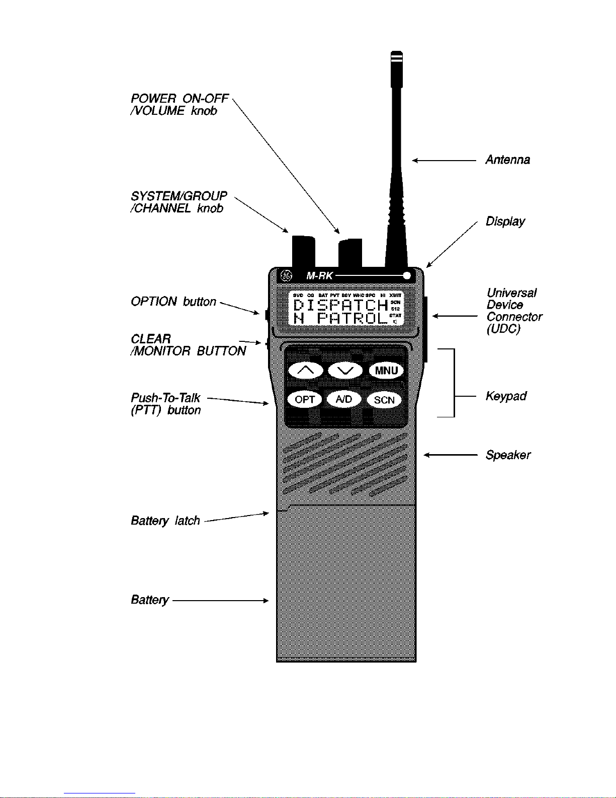
Figure 1 - M-RK II Scan Portable Radio
77
Page 8
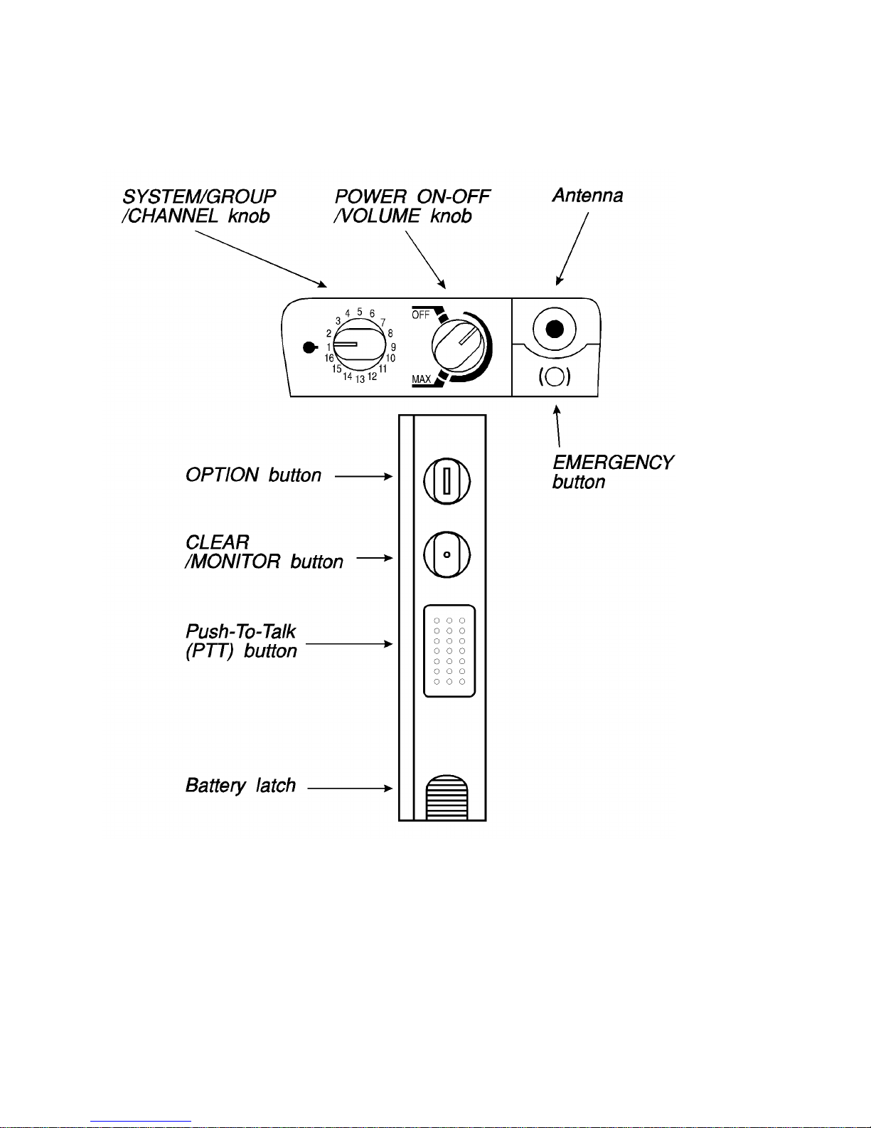
Figure 2 - Top And Partial Left Panel Views
88
Page 9

BBUUTTTTOONNS S AANND D KKNNOOBBSS
This section describes the primary function of the button
and knob controls. Other functions associated with these con
trols are detailed in later sections.
SSYYSSTTEEMM//
GGRROOUUPP//
CCHHAANNNNEELL
KKNNOOBB
Selects systems or groups/channels
(depending on programming). This is a 16 position rotary knob. See SYSTEM/
GROUP/CHANNEL SELECTION for de
tails.
PPOOWWEERR
OONN--OOFFFF//
VVOOLLUUMMEE
KKNNOOBB
Applies power to the radio and adjusts
the receiver’s volume. Rotating the con
trol clockwise out of detent applies
power to the radio. A single alert tone
sounds (if enabled through programming)
-
-
-
EEMMEERRGGEENNCCYY
to indicate the radio is operational.
Rotating the control clockwise increases
the volume level. Minimum volume levels
may be programmed into the radio to pre
vent missed calls due to a low volume set
ting. While adjusting the volume the dis
play will momentarily indicate the volume
level (i.e.
VVOOL L = = 3311
). The volume range is
from a minimum programmed level of zero
(displayed as
OOFFFF
in the display) up to 31
which is the loudest level.
Provides single button emergency chan
-
-
-
-
BBUUTTTTOONN
nel access. See the EDACS and conven
tional emergency sections for more de
tails.
-
-
99
Page 10

OOPPTTIIOONN
BBUUTTTTOONN
(Side)
Programmable per system.
CCLLEEAARR//
MMOONNIITTOORR
BBUUTTTTOONN
Serves several purposes depending on
the operating mode. In trunked mode, the
CLEAR/MONITOR button exits the cur
rent operation and removes all displays
associated with it. The radio and display
then return to the group receive state. In
conventional mode, pressing this button
unmutes the receiver so activity on the
selected channel can be monitored. When
pressed and held for approximately 3
seconds, this button toggles conven
tional channel decoding/encoding (Chan
nel Guard, Digital Channel Guard, T99) on
and off if programmed for the selected
-
-
-
channel.
PPUUSSHH--TTOO--TTAALLKK
BBUUTTTTOON N ((PPTTTT))
Enables the radio’s transmitter. Releas
ing PTT returns the radio to the receive
mode.
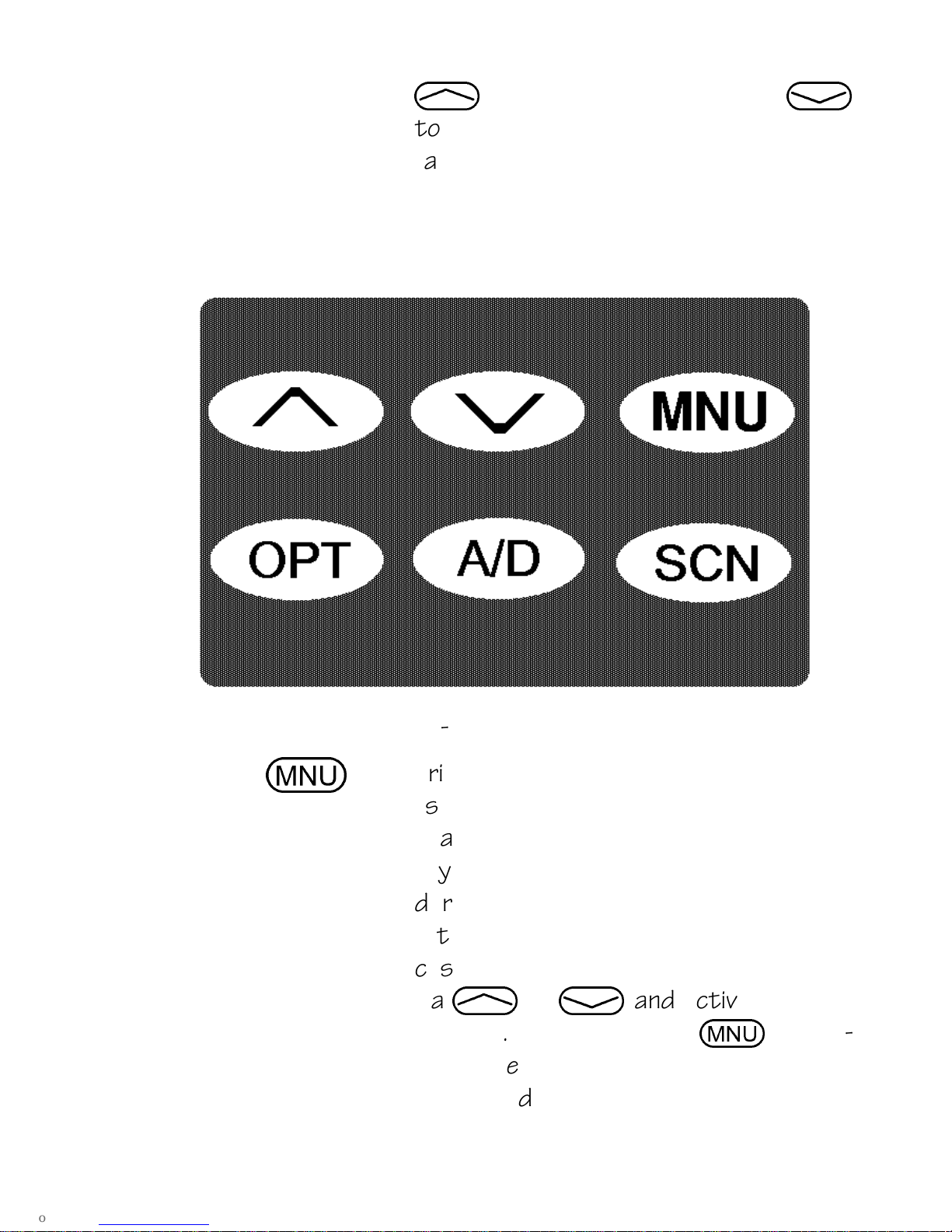
KKEEYYPPAADD
The keypad layout has a total of 6 keys. The keys have special
functions and are labeled as such using a symbol or abbreviated
word describing its primary function. Numeric entry is a secon
dary function of the keys. Each key is described below.
,
Primary function - changes the system or
-
-
.
1100
group/channel (depending on program
ming); secondary function - changes to a
-
Page 11
selection for items within a list. Press
,
to scroll in increasing order,
.
to scroll in decreasing order. To autoramp press and hold the key.
m
Figure 3 - M-RK II Scan Keypad
Primary function - accesses the menu
list. This is a list of additional features
that are not available directly from the
keypad. See MENU for details. Secon
dary function - activates a selected item
within a list. After the menu list is ac
cessed, select a menu item from the list
via
, or .
and activate it with
this key. Once activated,
ues its secondary function for activating
a selected parameter setting until the
m
contin
-
-
-
1111
Page 12
radio returns to its normal receive state.
This is similar to an enter key.
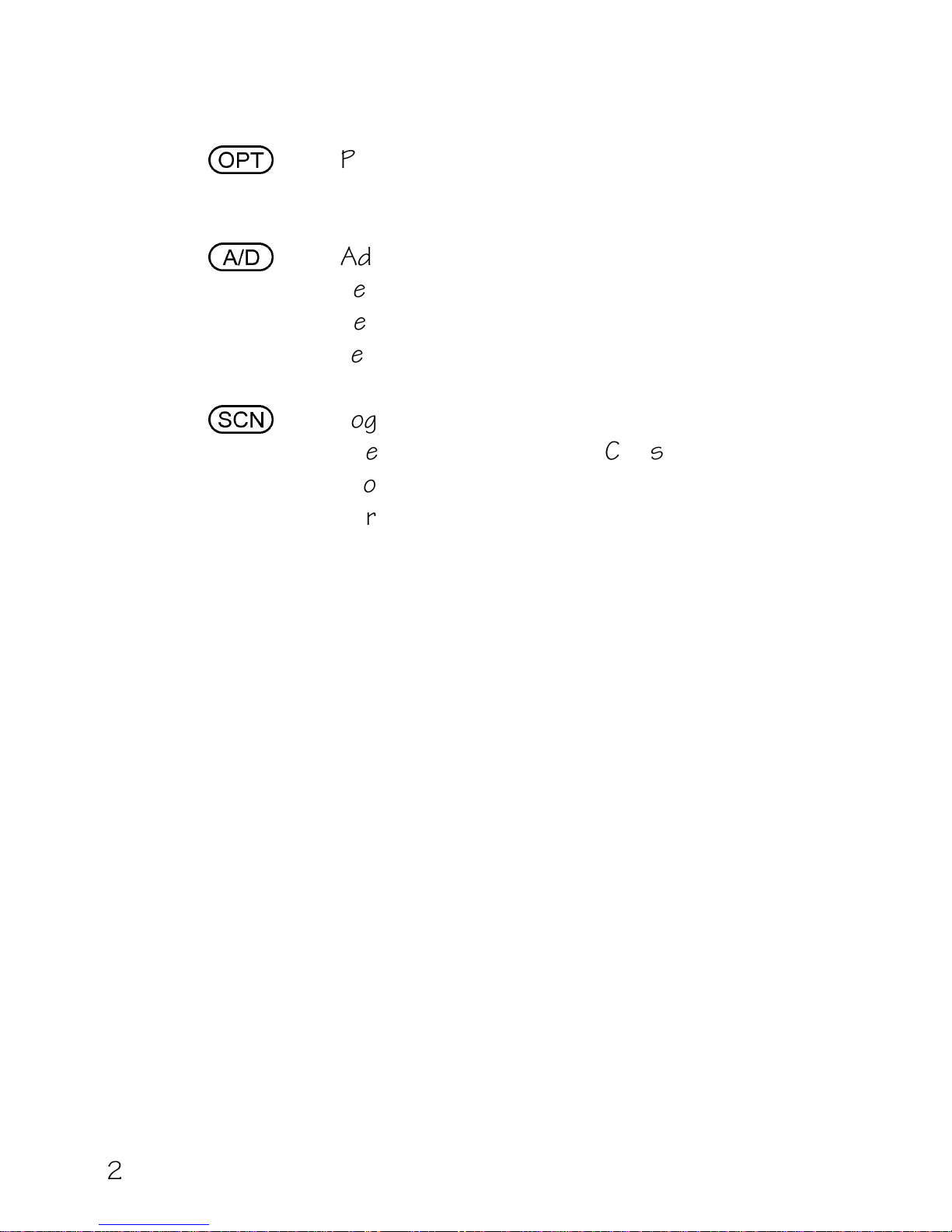
o
a
s
Programmable per system.
Adds or deletes selected groups or chan
nels from the scan list of the currently
selected system. See trunked and con
ventional scan section for details.
Toggles scan operation on and off. When
the radio is scanning,
SSCCNN
is on and all
groups or channels in the scanlist of the
currently selected system are scanned.
-
-
1122
Page 13
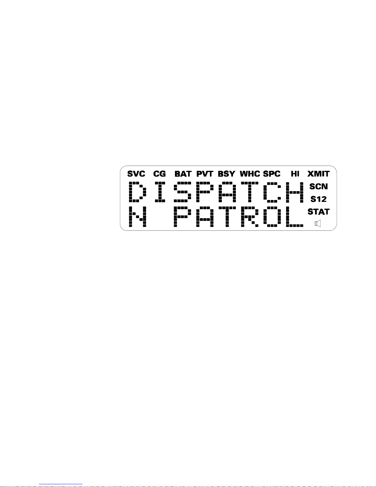
DDIISSPPLLAAYY
The radio’s display is shown below. The two character lines
are used to display system, group and channel names and also
operational messages to the user. Each line contains eight al
phanumeric character blocks. The 15 status indicators are used
to show the various operating conditions of the radio. If the
display back-lighting is programmed on, the display will illuminate
for a short period when any of the controls are operated.
The two display lines can be inverted to permit
Line 1
Line 2
-
Figure 4 - M-RK II Scan Display
easy viewing if the radio is worn on a belt or placed into a vehicular
charger. Refer to the MENU section to change the display (in
vert or contrast).
-
1133
Page 14

MMeessssaaggeess
During radio operation, various messages are displayed on
either line one or line two. Typical messages include control chan
nel status information, such as system busy or call denied, or
messages associated with the radio’s operation, (i.e. volume or
contrast adjust). These messages are described below.
Message
QUEUED
Name
Call Queued
Description
-
Trunked mode only.
Indicates the sys
tem has placed the
call in a request
queue.
SYS BUSY
System Busy
-
Trunked mode only.
Indicates the sys
-
-
-
DENIED
Call Denied
tem is busy, no
channels are cur
rently available, the
queue is full or an in
dividual call is being
attempted to a ra
dio that is cur
rently transmit
ting.
-
Trunked mode only.
Indicates the radio
is not authorized
to operate on the
selected system
-
-
-
-
-
CC SCAN
Control Channel Scan
1144
Page 15

-
Trunked mode only.
WA SCAN
Wide Area Scan
Indicates the con
trol channel is lost
and the radio has
entered the Con
trol Channel Scan
mode to search for
the control chan
nel.
-
Trunked mode only.
Indicates the con
trol channel is lost
and radio has en
tered the Wide
Area Scan mode to
-
-
-
-
-
TALKARND
*RXEMER*
Talk-around
Receive Emergency
search for a new
system (if enabled
through program
ming).
-
Conventional mode
only. Indicates the
radio is operating
on conventional
channels in talkaround mode (no
repeater).
-
Trunked mode only.
Indicates an emer
-
-
gency call is being
received. This mes
1155
-
Page 16

sage will be flashing
on line two.
*TXEMER*
VOL = 31
LOW BATT
Transmit Emergency
Volume Level
Battery Low
-
Trunked mode only.
Indicates an emer
gency call has been
transmitted. This
message will be
flashing on line two.
-
Indicates the cur
rent volume level.
The volume level dis
play ranges from
OFF (silent) to 31
(loudest).
-
Indicates the bat
-
-
-
-
UNKNOWN
Unknown ID
tery level is too low
for transmission.
This message dis
plays when press
ing PTT and trans
mitting is disabled
due to the low bat
tery condition.
-
Trunked mode only.
Indicates an indi
vidual call is being
received by an un
known radio ID. This
bypasses when the
-
-
-
-
-
-
1166
call is updated.
Page 17

TX DATA
Transmit Data
-
Trunked mode only.
Indicates when a
data call is being
RX DATA
DATA OFF
Receive Data
Data Off
transmitted. Dis
played on line one.
-
Trunked mode only.
Indicates when a
data call is being re
ceived. Displayed
on line one.
-
Trunked mode only.
Indicates when ra
dio is in data disable
state. Displayed on
line one.
-
-
-
DATA ON
KEY ZERO
Data On
Key Zero
-
Trunked mode only.
Indicates when ra
dio is toggled to
data enable state.
Displayed on line
one for two sec
onds.
-
Indicates that
cryptographic keys
have been erased
from radio memory.
-
-
PVT DIS
Private Disabled
-
Indicates that the
group or channel is
1177
Page 18

not programmed
for private mode
operation.
FRCD PVT
NO KEY #
Forced Private
No Key Number
-
Indicates that
group or channel is
pre-programmed
for private mode
operation and clear
mode is not possi
ble.
-
Indicates that the
correct crypto
graphic key is not
loaded for the se
lected group or
channel.
-
-
-
SSttaattuus s IInnddiiccaattoorrss
The 15 status indicators show the various operating char
acteristics of the radio. The indicators show operating modes
and conditions as follows:
SVC
Trunked mode only.
ON - indicates the radio is in an EDACS service
area and is in communication with the site con
troller via the control channel (CC).
FLASHING - indicates the EDACS is in the fail
soft mode (if enabled through programming).
OFF - indicates the radio is out of range or the
control channel is not available.
-
-
-
1188
Page 19

CG
Conventional mode only.
ON - indicates Channel Guard encode/decode is
enabled on the selected conventional channel.
BA T
PVT
ON - indicates the battery pack’s charge is low
and needs recharging.
Pr iv at e
ON - indicates the group or channel is enabled
to receive encrypted messages.
FLASHING - indicates an encrypted transmis
sion is being received.
-
1199
Page 20

BSY
Channel Busy In trunked mode:
ON - indicates the radio is transmitting or
receiving a call on the working channel.
FLASHING - indicates a call has been
queued.
In conventional mode:
ON - indicates a call is being received.
WHC
SPC
HI
Who Has Called (trunked mode only)
ON - indicates an individual call has been re
ceived, but not responded to. The indicator
turns OFF if the individual call mode is entered,
the system is changed or the radio is turned off
and back on.
ON - indicates the radio is in the special call se
lect/entry mode (Individual or Telephone Inter
connect).
ON - indicates the selected group or channel is
selected to transmit at high power.
OFF - indicates the selected group or channel is
-
-
-
selected to transmit at low power.
XMIT
ON - indicates the radio is transmitting.
When operating in a trunked system, the radio
may be programmed to automatically transmit
(without pressing PTT) to maintain digital com
munication with the site controller. will
turn on whenever the radio is transmitting.
2200
-
Page 21

SCN
ON - indicates the scan mode is enabled.
XXMMIITT
S
1
2
ON - indicates the selected group or channel is
in the scan list.
ON - (conventional mode only) indicates the se
lected channel is designated as the priorityone scan channel.
ON - (conventional mode only) indicates the se
lected channel is designated as the prioritytwo scan channel.
ON - (conventional mode only) indicates that
the selected channel has T99 decode option
enabled.
-
-
UUNNIIVVEERRSSAAL L DDEEVVIICCE E CCOONNNNEECCTTOOR R ((UUDDCC))
The Universal Device Connector (UDC) provides connections
for external accessories such as a headset or a speaker-micro
phone. When the radio is locked in a vehicular charger/repeater
the UDC provides the audio and control connections between
the radio and the vehicular charger/repeater. The UDC is also
used to program and service the radio.
AALLEERRT T TTOONNEESS
-
The M-RK II Scan radio also provides audible alert tones or
"beeps" to indicate the various operating conditions. These alert
tones can be enabled or disabled through programming.
2211
Page 22

CCaall ll OOrriiggiinnaattee
A short mid-pitched alert tone sounds after keying the
radio (Push-To-Talk button is pressed). This indicates the radio
has been assigned a working channel or that the radio is trans
mitting on a conventional channel and voice communication may
begin immediately. In conventional mode, this tone may be de
layed after the PTT button is pressed due to GE-STAR signalling
(if enabled through programming).
AAuuttookkeey y ((TTrruunnkkeed d MMoodde e OOnnllyy))
After being placed in queue or releasing the PTT button prior
to a working channel assignment, the site calls the radio when a
channel becomes available. At this point, the radio automatically
keys the transmitter (autokey) for a short period to hold the
channel. The radio sounds a mid-pitched tone when it is clear to
talk; immediately press the PTT button to keep the assigned
-
-
channel.
CCaall ll QQuueeuueed d ((TTrruunnkkeed d MMoodde e OOnnllyy))
A high-pitched tone after pressing the PTT button indicates
the system has placed the call request in the queue. The receiv
ing unit(s) also hear the tones, indicating they will receive a call
shortly. If the the PTT button is released, the radio will autokey
whenever a channel becomes available (see Autokey).
SSyysstteem m BBuussy y ((TTrruunnkkeed d MMoodde e OOnnllyy))
Three low-pitched beeps will be heard if the radio is keyed
when the system is busy, if no channels are available for sending
-
the message, if the call queue is full, or if an individual call is being
2222
Page 23

attempted to a radio that is transmitting. Releasing the PTT
button and re-keying initiates a new channel request.
CCaall ll DDeenniieed d ((TTrruunnkkeed d MMoodde e OOnnllyy))
If the radio is keyed and a low pitched tone is heard then the
radio is not authorized on the system that has been selected.
CCaarrrriieer r CCoonnttrrool l TTiimmeerr
If the programmed time for continuous transmission is ex
ceeded, five short high-pitched warning tones followed by a long
low-pitched tone will be heard. The transmitter will shut down
shortly after hearing the alert, interrupting communications.
Release and re-key the PTT button to maintain communications.
This will reset the carrier control timer and turn the transmitter
back on.
LLoow w BBaatttteerry y WWaarrnniinngg
A low-pitched tone is heard and comes on indicating
that the battery voltage is low. The radio will continue to receive
and transmit.
-
LLoow w BBaatttteerry y AAlleerrt t ((TTrraannssmmiit t LLoocckkoouutt))
If the radio is keyed and a low-pitched tone or two tones
repeated until PTT or CLEAR button is pressed (either condition
is pre-programmable) is heard and LOW BATT is displayed, the
battery is discharged and the radio will not transmit. The radio
will still be able to receive calls until the battery is discharged
beyond the point of operation, after which the battery will need
to be recharged to resume normal operation.
BBAATT
2233
Page 24

KKeey y PPrreess ss AAlleerrtt
A short tone or "beep" sounds to indicate a key has been
pressed. A short low-pitched tone indicates no action was
taken because the key is not active in the current mode.
OOPPEERRAATTIIOONN
TTUURRNNIINNG G OON N TTHHE E RRAADDIIOO
Rotate the POWER ON-OFF/VOLUME knob clockwise, out of
detent to turn the radio on. (Ensure the antenna and battery
pack are properly connected prior to power on.) A short beep (if
enabled through programming) indicates the radio is ready for
operation. The display indicates, if programmed, the last se
lected system name on line one and the last selected group or
channel name on line two.
In the EDACS trunked environment, upon acquisition of the
control channel, will come on. If communication with the
system’s control channel cannot be established, will not
turn on. This may occur if, for example, the radio is out of range
of the trunking site. It may be necessary to move to another
location or select another trunking system to reestablish the
control channel link for trunked mode operations.
SSEELLEECCTTIIOON N MMOODDE E RRUULLEESS
-
Many operations require selection from a list such as sys
tem, group or phone number. This selection process is handled in
the same manner for all lists.
the CLEAR/MONITOR button are used during the selection
process. The following example systems list is used to explain
the process:
2244
,,.,m, o
SSVVCC
-
, and
Page 25

SSVVCC
SYSTEM
1 NORTH
2 SOUTH
3 EAST
4 WEST
After entering a selection mode, the following generic dis
play format will appear.
X
X
X
X
X
X
X
X
Y
Y
Y
=
Z
Z
Z
Line one shows the currently selected item name
(XXXXXXXX) from the list. Line two indicates the list (YYY) that
the selection is to be made from and the number of the selected
-
item (ZZZ) within the list. (In some cases the information on
lines 1 and 2 will be the opposite of this example.) If SYSTEM 2
is the current selection, the display appears as follows:
S
O
U
T
H
S
Y
S
Line one contains the current system name,
two,
SSYYS S = = 22
, indicates that selection is from the system list
=
2
SSOOUUTTHH
, and line
and it is the second system within the list.
A new system from the list is selected by using
.
to scroll through the list in increasing and decreasing
order respectively. In the previous example, pressing
,
.
and
se
-
lects the EAST system as shown in the next display.
E
A
S
T
2255
Page 26
S
Y
S
=
3
The radio may be programmed to wrap around from one end
of a list to the other end or to stop at the ends.
To exit the selection mode, press the CLEAR/MONITOR but
ton or wait for the timeout.
MMEENNUU
The menu function accesses features that are not available
directly from the keypad. The order and specific number of menu
items available is configurable through programming. Upon radio
power up, the menu item that is at the beginning of the menu list
will always be displayed first. Subsequent access to the menu
function will return the last menu item that was shown in the
display. To enter the menu mode, press
m,,,.
, and the CLEAR/MONITOR button are used
m
during the selection process. All of the selection mode rules
previously detailed apply to the menu item selection process
-
.
with the exception of direct access. The radio will continue to
receive and transmit normally while in the menu function.
NNOOTTEE
While in system, group or channel selection mode, the radio
continues to receive calls normally and continues scanning
if it is enabled. If a call is received during the selection mode
process the radio will return to the normal receive mode
display. Continuing with the selection process will return the
display to the same point in the selection process if the
selection mode time out has not yet expired. Any press of
the PTT button during the selection mode process will initi
-
ate transmission and exit the selection mode.
2266
Page 27

A new item is displayed by using
,
and
.
to scroll
through the list in increasing and decreasing order respectively.
The displayed menu item is made active by pressing
m
.
After entering the menu selection mode, the following ge
neric display format will appear.
M
E
N
U
Y
Y
Y
Y
Y
Y
Y
Y
Line one indicates the radio is in the menu selection mode.
Line two indicates the menu item (YYYYYYYY) that is to be
viewed or changed (some menu items provide radio information
and do not have changeable parameters).
An example of the menu item selection process and menu
item parameter change is detailed below for the backlight menu
-
item.
PRESS:
m
The menu mode is entered.
PRESS:
PRESS:
,
m
or
.
M
B
C
K
until the display shows:
E
N
U
L
G
H
T
The backlight menu item is activated and the display will be
similar to the following:
B
Y
C
Y
K
Y
L
Y
=
Y
X
Y
X
Y
X
Y
2277
Page 28

Line one shows the active menu item and its current pa
rameter setting (XXX). Line two shows the currently selected
system or group name (YYYYYYYY).
The menu item’s parameter setting shown in the display can
-
now be changed by using
,
or
.
to scroll through the
list of parameter values. Once the desired setting is reached
press
m
For menu items that display radio information pressing
.
will scroll through a list of informational displays. The
to store the value and return the normal display.
,
or
menu items are listed Table 1.
Table 1 - Menu Item Information
FFEEAATTUURREE
Keypad Lock KEY LOCK
Backlight Adjust BCK LIGHT
Contrast Adjust CONTRAST
Transmit Power Select TX POWER
Radio Revision REVISION
DDIISSPPLLAAYY
Invert (View) Display INVERT
Toggle Scan On/Off SCAN
Toggle Private Mode On/Off PRIVATE
Display Current AEGIS Encryption Key DISP KEY
Display Current Home Group/Channel HOME
Select Desired System SYS SEL
Add Group/Channel to Scan List SCAN ADD
Delete Group/Channel From Scan List SCAN DEL
Add/Delete Scan List SCAN A/D
Select Telephone Numbers F rom
Phone List
Toggle Data Operation On/Off NO DATA Trunked Only
Toggle Conv P1 Scan On/Off ECP1SCAN Trunked Only
Select Individual Call from IC List IND CALL Trunked Only
PHN CALL
2288
Page 29

Select Status Message
STATUS 0 - STATUS 9 Trunked
Only
NNOOTTEE
The TX POWER menu item, when selected, toggles HI/LO
power. It does not use
∧
or
to scroll nor an additional press
∨
of the MNU button.
Select Group GRP SEL Trunked Only
Toggle Talkaround Feature On/Off TALK ARND Conv entional Only
Select Channel CHN SEL Conventional Only
BBUUTTTTOON N AANND D KKEEYYPPAAD D RREEAASSSSIIGGNNMMEENNTT
Pre-programming the radio using the PC Programming Soft
ware permits the reassignment of button and keypad key func
tions. The EMERGENCY, OPTION, CLEAR/MONITOR and PTT
buttons along with the front panel keypad keys can be reas
signed different functions. For Example, the
assigned as the HOME key, the
o
key could be assigned as
m
key could be
-
-
-
the VIEW key, etc.
The operating procedures that follow assume that the but
tons and keypad keys operate as marked. If they have been
reassigned, Table 2 should be completed to show the new func
tion(s). Substitute the new assigned keys when using the op
erating procedures.
-
-
-
2299
Page 30

Table 2 - Button and Key Assignments
SSTTAANNDDAARRD D AASSSSIIGGNNMMEENNTTSS
OPTION (Side)
CLEAR/MONITOR
PTT
EMERGENCY
,
.
m
o
a
s
RREEAASSSSIIGGNNMMEENNTT
3300
Page 31

SSYYSSTTEEMM//GGRROOUUPP//CCHHAANNNNEEL L SSEELLEECCTTIIOONN
In the following description of SYSTEM/GROUP/ CHANNEL
SELECTION, the term group is used for both group and channel.
The M-RK II Scan SYSTEM/GROUP/CHANNEL knob and the
,,.
pair are programmable for maximum flexibility. If
the SYSTEM/GROUP/CHANNEL knob is assigned to select
groups, then the
,, .
keys are assigned to select
systems. If the SYSTEM/GROUP/CHANNEL knob is assigned
to select systems, then the
,, .
keys are assigned to
select groups. System, group and channel selection is the pri
mary function for these controls.
Either systems or groups can also be selected by entering
the select mode and following the selection mode rules de
scribed earlier. Only the selection assigned as the primary func
tion of the
,, .
pair will be available for this method of
direct selection. For example, if system selection is the primary
function of the
,, .
pair then only the system select
-
-
-
mode will be usable and direct group select will be unavailable. The
system select or group select modes are entered by pressing
m
from the standard receive mode. Using
,, .
af
ter entering a particular selection mode in this manner is the
secondary function of this key.
SSyysstteem m SSeelleeccttiioonn
Several methods, some of which depend on programming,
can be used to select a new system. These procedures are
presumed to be starting from the normal receive display.
METHOD 1:
3311
Page 32

If system selection is programmed to the SYS
TEM/GROUP/CHANNEL knob, select a system
by turning the SYSTEM/GROUP/CHANNEL
knob to the desired system number position (1-
16). The display registers the new system name
on line one. If the knob is moved to a position
-
METHOD 2:
METHOD 3:
greater than the number of programmed sys
tems, the highest programmed system will re
main selected.
If system selection is programmed as the pri
mary function of
,
system by pressing
,
and
or
.
.
, select a
to scroll
through the system list. The display registers
the new system name on line one.
Press
m
to enter the system select mode
and follow the selection mode rules detailed
earlier. If system selection is programmed to
the SYTEM/GROUP/CHANNEL knob, direct ac
-
-
-
-
cess to systems will not be available. Presses of
,
or
.
will scroll through different
sets of 16 systems each (banks) if more than
16 systems are programmed into the radio. The
systems within each bank are then selectable
via the SYSTEM/GROUP/CHANNEL knob as
described previously in METHOD 1.
GGrroouup p AAnnd d CChhaannnneel l SSeelleeccttiioonn
Several methods, some of which depend on programming,
can be used to select a new group or channel. These procedures
are presumed to be starting from the normal receive display.
3322
Page 33

METHOD 1:
If group selection is programmed to the SYS
TEM/GROUP/CHANNEL knob, select a group by
turning the SYSTEM/GROUP/CHANNEL knob
to the desired group number position (1-16). The
display registers the new group name on line
two. If the knob is moved to a position greater
than the number of programmed groups, the
highest programmed group will remain selected.
-
METHOD 2:
METHOD 3:
If group selection is programmed as the pri
mary function of
,
group by pressing
,
and
or
.
.
to scroll
select a
through the group list. The display registers
the new group name on line two.
Press
m
to enter the group select mode
and follow the selection mode rules detailed
earlier. If group selection is programmed to the
SYSTEM/GROUP/ CHANNEL knob, direct ac
cess to groups will not be available. Presses of
,
or
.
will scroll through different
sets of 16 groups each (banks) if more than 16
groups are programmed into the radio. The
-
-
TTRRUUNNKKEED D MMOODDE E OOPPEERRAATTIIOONN
Digital trunking provides fast communication access at all
times, even during busy hours. In this mode the operator selects
a communications system and group and the audio communica
groups within each bank are then selectable via
the SYSTEM/GROUP/CHANNEL knob as de
scribed previously in METHOD 1.
3333
-
-
Page 34

tion or working channel (WC) is allocated through digital signal
ling with the site.
RReecceeiivviinng g A A CCaallll
-
1.
2.
3.
Turn on the radio by rotating the POWER ON-OFF/VOLUME
knob clockwise (out of detent). A short alert signal (if en
abled through programming) indicates the radio is ready to
use.
The display shows the last selected or the power up (de
pending on programming) system and group names and
indicates if the radio has acquired the system control
channel by turning on . If the radio is unable to obtain
a control channel, line two shows CC SCAN and will
remain off.
Adjust the POWER ON-OFF/VOLUME knob to the desired
volume level.
-
-
4.
5.
6.
7.
Select the desired system and group. The display indicates
the current system and group names.
The radio is now ready to receive calls.
GROUP CALL - When the radio receives a group call, it un
mutes on the assigned working channel and
comes on. Line one shows GR followed by the logical ID
number (if received) of the unit sending the message, or the
associated name if the ID number is found in the individual
call list.
-
33 44
Page 35

INDIVIDUAL CALL - When the radio receives an individual call
(a call directed only to the user’s radio), it unmutes on the
assigned working channel and turns on and . Line
one shows ID followed by the logical ID number of the unit
sending the message, or the associated name if the ID
number is found in the individual call list.
Responding to the call prior to the programmed call-back
time-out will automatically direct the call to the originating
unit. If the caller’s ID is not received, UNKNOWN will display
and there will be no call-back hangtime.
SSeennddiinng g A A CCaallll
1.
2.
3.
4.
Turn on the radio and set the POWER ON-OFF/VOLUME
knob to the desired volume level. Select the desired system
and group.
Press and hold the PTT button. The radio will display
, the system and group names and perform the neces
sary signalling required to obtain a communication channel.
When the working channel is assigned, and
are turned on and a short beep sounds indicating that
communication can begin.
SSVVCC
Hold the radio approximately three inches from the mouth
and speak in a normal voice into the microphone (located
SSVVCC
between
,
and
.
on the keypad).
-
5.
Release the PTT button when the transmission is complete
and listen for a reply.
3355
Page 36

EEmmeerrggeennccy y OOppeerraattiioonn
The radio’s ability to declare an emergency, clear an emer
gency, remain locked on an emergency system and group, and
the emergency audio and display freeze can each be enabled or
BBSSYY
disabled through programming. When an emergency is declared
scanning will stop and restarts only after the emergency has
been cleared.
RReecceeiivviinng g AAn n EEmmeerrggeennccy y CCaallll
When receiving an emergency call from the selected group
and system, an alert beep is heard and
comes on. The message
BBSSYY
**RRXXEEMMEERR**
WWHHCC
flashes in the display on line
two until the emergency condition is cleared. Follow standard
emergency procedures.
-
DDeeccllaarriinng g AAn n EEmmeerrggeennccy y CCaallll
To send an emergency call to the selected system and group
(or on an optionally preprogrammed group), proceed as follows:
1.
Press and hold the red EMERGENCY button that is on top
of the radio in front of the antenna for approximately one
second (this time is programmable and therefore could be
longer or shorter; check with the system administrator).
The radio will transmit an emergency call request with the
radio ID until an emergency channel assignment is received.
2.
When the working channel assignment is received, the radio
sounds a single beep (Autokey alert tone) indicating it is
XXMMIITT
ready for voice transmission.
**TTXXEEMMEERR**
flashes on line two in the display until the emer
gency is cleared.
3366
-
Page 37

3.
Press PTT and speak into the microphone in a normal voice.
turns on.
BBSSYY
XXMMIITT
NNOOTTEE
If two or more tones, or a high pitched tone is heard, the
system may be busy and the call request has been placed in
queue or the request has been denied for some reason. Refer
to the ALERT TONES section for more details.
4.
Release PTT when the transmission is complete and listen
for a reply.
5.
The emergency can be cleared by pressing and holding the
CLEAR/MONITOR button followed by pressing the EMER
GENCY button then releasing both buttons.
WWiidde e AArreea a SSyysstteem m SSccaannnniinngg
The M-RK II Scan radio may be programmed for wide area
system scan operation for multi-site applications. Upon the
loss of the currently selected system’s control channel, radios
may be programmed to automatically scan the control channels
of other systems. If a new control channel is found, the radio will
-
switch to the new system and sound an alert tone.
The radio may also be programmed for priority system scan.
A priority system may be assigned among the systems pro
grammed into the radio. Radios programmed in this manner will
check for the priority trunked system’s control channel at a
programmable rate ranging from 1 to 16 minutes. This priority
scan timer is reset each time the PTT button is pressed or when
-
BBSSYY
3377
Page 38

a call is received. If the priority system control channel is found,
the radio will automatically switch to the priority system.
SSccaannnniinng g TTrruunnkkeed d GGrroouuppss
Groups which have been previously added to the scan list on
a per system basis may be scanned. Each system’s group scan
list is retained in memory when the radio is turned off or when
the battery pack is removed.
The following procedures outline scan operations for trunked
groups. See the conventional mode operating procedures for
specific procedures on conventional channel scanning.
AAddddiinng g aannd d DDeelletetiinng g GGrroouupps s oon n SSccaan n LLiisstt
1.
Scan must be off to add or delete groups from scan list. If
the status flag is on, press
s
off.
2.
Select the desired group using the SYS
TEM/GROUP/CHANNEL knob and/or
If the selected group is currently on the list, the status
flag will be on.
BBSSYY
3.
Press the
a
key repetitively until the desired priority
indicator appears: for non-priority, for priority two,
for priority one, or no indicator to remove the group from
key to turn scan
, .
-
keys.
the scan list. If a new priority group is selected, the pre
vious corresponding priority group will become a lower pri
ority scan group. One of the following messages may be
momentarily displayed:
SCAN DIS
The radio is not programmed to scan.
3388
-
-
Page 39

FIXED P1
A priority one group has been pre-programmed
into the radio. A new priority one group cannot
be selected.
FIXD LST
A fixed scanlist has been pre-programmed into
the radio. It is not possible to change the list
without reprogramming the radio.
4.
To add or delete additional groups, repeat steps 2 and 3.
A group can also be deleted from the scan list, if it is not the
currently selected group, by pressing
a
during scan opera
tion while the radio is displaying the unwanted group. The group
will be deleted from the system’s group scan list in the same
manner as if done using the steps above. Deletions done in this
manner will not remain deleted if the radio is turned off and then
back on.
-
TTuurrnniinng g SSccaan n OOnn
1.
Toggle scan operation on by pressing
on when the radio is scanning.
2.
When a group on the scan list receives a channel assign
ment, the radio unmutes on the assigned channel and
comes on. Line one shows
number (if received) of the unit sending the message, or the
associated name if the ID number is found in the individual
call list. The group name displays on line two.
If the radio detects a call from the currently selected group,
-
it has priority and the radio will switch to the selected
s.
GGRR
followed by the logical ID
will turn
-
group call.
3399
Page 40

The radio will continue scanning if a new group is selected
-
when scan is on.
Pressing the PTT button when scan is on will cause the radio
-
to transmit on the displayed group or to the currently
selected group (depending on programming).
TTuurrnniinng g SSccaan n OOffff
SS
SSCCNN
Toggle scan operation off by pressing
s
. The radio will
resume operation on the selected group.
SS
22
IINNDDIIVVIIDDUUAAL L CCAALLLLSS
11
RReecceeiivviinng g AAnnd d RReessppoonnddiinng g TTo o AAn n IInnddiivviidduuaal l CCaall ll ((TTrruunnkkeed d MMooddee
OOnnllyy))
When the radio receives an individual call (a call directed only
to the user’s radio), it unmutes on the assigned working channel
and turns on and
. Line one shows ID followed by the logical ID number of the
unit sending the message, or the associated name if the ID
number is found in the individual call list. The radio can be pro
grammed to ring when an individual call is received. If enabled, the
ring begins five seconds after the caller unkeys and will continue
until the PTT button, the CLEAR/MONITOR button or the indi
vidual call mode is entered when the
m
button is pressed.
If a response is made to the call prior to the programmed
call-back time-out, the call will automatically be directed to the
originating unit. If a response is not made before the call-back
-
-
time-out, the radio will return to normal receive display, but
will remain on. If the caller’s ID is not received, UNKNOWN will
4400
Page 41

display for the duration of the call and there will be no call-back
hangtime.
SSCCNN
BBSSYY
4411
Page 42

To respond after the call-back time-out, press
m
key
then
,
or
.
while is on and the display will show
the caller’s ID. The individual call selection mode is now active and
the selection mode rules apply. The caller can be responded to
by pressing the PTT button if no other selection is made. Be
cause the latest caller’s ID is stored in location 0 and the radio
is now in the individual selection mode, the caller can be selected
directly by pressing
m
. If the caller is selected in this man
ner proceed with the call by pressing the PTT button.
SSeennddiinng g AAn n IInnddiivviidduuaal l CCaall ll ((TTrruunnkkeed d MMoodde e OOnnllyy))
The following procedures describe how to initiate and com
plete an individual call.
WWHHCC
BBSSYY
-
1.
2.
To select a previously stored individual, enter the individual
call mode using the
.
to scroll through the list of stored individuals.
m
key feature followed by
,
or
turns on. The selection mode rules apply.
Press the PTT button; the radio performs the necessary
signalling to obtain a communication channel. When the
signalling is complete and the radio is clear to transmit,
turns on, turns off and the channel access tone
sounds. Line one shows the called individual’s name if found
in the list of stored individuals or
ID number of the unit being called. The message
displays on line two. Proceed with the message.
WWHHCC
IIDD
followed by the logical
**IINNDDVV**
4422
Page 43

TTEELLEEPPHHOONNE E IINNTTEERRCCOONNNNEECCT T CCAALLLLSS
WWHHCC
RReecceeiivviinng g A A TTeelleepphhoonne e IInntteerrccoonnnneecct t CCaall ll ((TTrruunnkkeed d MMoodde e OOnnllyy))
Receiving a telephone interconnect call is identical to receiv
ing an individual call. See the DTMF Overdial Operation section if
access to services requiring "over-dial" is needed. Overdial opera
tions are available for any special call whether it is an individual
call or a telephone interconnect call.
SSeennddiinng g A A TTeelleepphhoonne e IInntteerrccoonnnneecct t CCaall ll ((TTrruunnkkeed d MMoodde e OOnnllyy))
Use the following procedures to initiate and complete a Tele
phone Interconnect call:
1.
To select a previously stored phone number, press
followed by
,
or
.
to scroll through the list of
m
stored phone numbers. turns on. The selection mode
-
-
-
2.
3.
rules apply.
SSPPCC
Press and release the PTT button; the radio performs the
necessary signalling to obtain a communication channel.
When the signalling is complete and the radio is clear to
transmit, turns on,
turns off and the channel access tone sounds. Line one
shows the accompanying name selected from the list of
XXMMIITT
stored numbers. The message
SSPPCC
**PPHHOONNEE**
displays on line
two. The radio then automatically transmits the pro
grammed number stored in the special call queue.
The telephone ringing will be heard. When someone answers
the phone, press the PTT button and speak into the micro
-
-
phone. Release the PTT button to listen to the callee. Un
-
4433
Page 44

successful interconnect signalling returns the radio to the
normal receive mode and the number remains displayed
until the special call is cleared or the time-out expires or
another group or system is selected. Terminate a call by
pressing the CLEAR/MONITOR button.
4.
To terminate the call, momentarily press the CLEAR/MONI
TOR button.
DDTTMMF F OOvveerrddiiaal l / / CCoonnvveennttiioonnaal l MMoodde e TTeelleepphhoonne e IInntteerrccoonnnneecctt
Once the radio has established a connection to the public
telephone system, it may be necessary to "over-dial" more digits
to access banking services, answering machines, credit card
calls or other types of systems that require DTMF (Dual-Tone
Multi-Frequency) access digits. Overdial operation can also be
used to initiate a telephone interconnect call via DTMF signalling
if a dial tone has already been accessed on the system. This is
the method that is used for making a telephone interconnect
call while operating in the conventional mode but will also func
tion in trunked mode if a dial tone is directly accessible. Tele
SSPPCC
phone numbers and other number sequences for overdialing can
-
-
-
be stored in the phone list when programming the radio. These
numbers are accessed by pressing
selection mode rules.
The following steps are required to dial these numbers:
1.
Follow the procedure in Sending A Telephone Interconnect
Call (Trunked Mode Only) to establish a connection to the
telephone system or consult the system administrator for
the procedure to access a dial tone on the trunked or
conventional system.
4444
m
XXMMIITT
, then following the
SSPPCC
Page 45

2.
Overdial numbers are transmitted by entering the phone
mode using the
Press
m
to enter the overdial select/entry mode and
m
button.
follow the selection mode rules to call up a stored number
from the phone list. turns on. Press PTT to send the
overdial sequence once. If the number needs to be transmit
ted again it must be selected or entered again (this pre
vents unwanted numbers from being sent the next time the
NNOOTTEE
The M-RK II Scan radio is capable of simplex (one way)
conversation only. The callee can only hear the radio if
the PTT button is pressed (the radio is transmitting)
and the callee can only be heard when PTT is released
-
-
(the radio is receiving).
PTT button is pressed during the call).
This overdial select/entry mode remains active until the call
is dropped, cleared, or
m
is pressed. The overdial se
lect/entry mode can be re-entered if the call is still active
by pressing
m
.
CCOONNVVEENNTTIIOONNAAL L MMOODDE E OOPPEERRAATTIIOONN
The radio functions in the conventional mode when using
conventional communications channels (non-trunked). Each
-
channel consists of a preset frequency pair for transmit and
receive during repeater operation, or a single frequency for both
transmit and receive during talk-around (no repeater) opera
tion. To use this mode, the operator selects a conventional
-
4455
Page 46

system which includes one or more conventional channels. Each
conventional channel may have one or more features, such as
Channel Guard, programmed when the channel is selected.
The CLEAR/MONITOR button unmutes the receiver so activ
ity on the selected channel can be monitored. When pressed and
held for approximately 3 seconds this button toggles conven
tional channel decoding (Channel Guard, Digital Channel Guard
or T99) on and off if programmed for the selected channel.
RReecceeiivviinng g A A CCaallll
1.
Turn on the radio by rotating the POWER ON-OFF/VOLUME
knob clockwise (out of detent). A short alert signal (if en
abled through programming) indicates the radio is ready to
use.
2.
Adjust the POWER ON-OFF/VOLUME knob to the desired
-
-
-
volume level.
SSPPCC
4466
Page 47

3.
Select the desired conventional system and channel. The
display indicates the current conventional system and
channel names.
4.
5.
The radio is now ready to receive calls.
When the radio receives a call (and the correct encoding is
decoded, if programmed and enabled), it unmutes on the
channel and comes on.
SSeennddiinng g A A CCaallll
1.
Turn on the radio and set the POWER ON-OFF/VOLUME
knob to the desired volume level. Select the desired conven
tional system and channel.
2.
Ensure that the channel is not busy by pressing the
CLEAR/MONITOR button to momentarily disable any chan
-
-
3.
4.
5.
nel decoding and unmute the receiver or observe the display
for the absence of . If the Channel Busy Lockout fea
ture is programmed for the selected channel, the radio will
not transmit when the channel is busy.
Press and hold the PTT button. The radio will display
and a short beep sounds (if programmed) indicating
that communication can begin.
Hold the radio approximately three inches from the mouth
and speak in a normal voice into the microphone (located
between
,
and
.
on the keypad).
Release the PTT button when the transmission is complete
-
and listen for a reply.
4477
Page 48

EEmmeerrggeennccy y OOppeerraattiioonn
If enabled, GE-STAR emergency signalling can be transmit
ted when operating in the conventional mode. This GE-STAR
signalling will transmit 5 times with a delay between each trans
mission. To send an emergency call on the selected conventional
system and channel (or on an optionally preprogrammed con
ventional emergency system and channel), proceed as follows:
BBSSYY
Press and hold the RED EMERGENCY button that is on the
top of the radio in front of the antenna for approximately
one second (this time is programmable and therefore could
be longer or shorter; check with the system administra
tor). The radio displays
and proceeds to transmit the pre-programmed GE-
STAR emergency signalling sequence.
-
-
-
-
GE-STAR is programmed to transmit in one of the following
methods:
BBSSYY
METHOD 1:
GE-STAR is transmitted on the selected chan
nel. If the channel is changed the emergency sig
nalling will continue to be transmitted on the
newly selected channel.
METHOD 2:
XXMMIITT
Same as METHOD 1 but the radio will lock on to
the currently selected channel. Any attempts
to change the channel will be disabled.
METHOD 3:
GE-STAR is transmitted on a pre-programmed
conventional emergency system and channel
-
-
regardless of the selected channel. In this case
the selected channel is available for voice trans
4488
-
Page 49

mission and the radio will periodically change to
the pre-programmed emergency system and
channel to send the emergency signalling and
then change back to the selected channel.
METHOD 4:
Same as METHOD 3 but the radio will lock on to
the pre-programmed emergency system and
channel. Any attempts to change the channel
will be disabled.
The emergency state can be cleared by turning the radio off
and then back on.
SSccaannnniinng g CCoonnvveennttiioonnaal l CChhaannnneellss
Channels which have been previously added to the scan list
on a per system basis may be scanned. The selected channel is
scanned (if enabled through programming) whether or not it is
in the scan list. Each conventional system’s channel scan list is
retained in memory when the radio is turned off or when the
XXMMIITT
battery pack is removed.
The scan rate will vary depending upon the number of chan
nels in the scan list and whether or not the radio is programmed
to scan for channels with decoding enabled. Fewer channels will
result in a faster scan rate. If programmed for dual-priority scan
operation, the priority-one, priority-two and the remaining scan
list channels are scanned. Once a signal is detected and the
correct encoded squelch signal is decoded (if programmed), the
radio receives the message and displays the received scan chan
nel. At the same time, scanning continues on the priority-one
and priority-two channels. Should the priority-one or prioritytwo channel carrier, regardless of encoded squelch decoding, be
detected while a non-priority channel is being received, the dis
-
4499
Page 50

play name is updated, or comes on and the received channel
is switched to the priority channel. Scanning of the priority-one
channel will continue if a message is being received on the prior
ity-two channel.
The following procedures outline scan operations for conven
tional channels.
AAddddiinng g aannd d DDeelletetiinng g CChhaannnneells s oon n SSccaan n LLiisstt
1.
Scan must be off to add or delete channels from scan list.
If the status flag is on, press
s
key to turn scan
off.
2.
Select the desired channel using the SYS
TEM/GROUP/CHANNEL knob and/or
, .
keys.
-
-
-
If the selected channel is currently on the list, the
status flag will be on.
3.
Press the
indicator appears: for non-priority, for priority two,
for priority one, or no indicator to remove the channel from
the scan list. If a new priority channel is selected, the
previous corresponding priority channel will become a lower
priority scan channel. One of the following messages may
be momentarily displayed:
SCAN DIS
FIXED P1
a
key repetitively until the desired priority
The radio is not programmed to scan.
A priority one channel has been pre-pro
grammed into the radio. A new priority one
-
channel cannot be selected.
FIXD LST
5500
Page 51

A fixed scanlist has been pre-programmed into
the radio. It is not possible to change the list
without reprogramming the radio.
4.
To add or delete additional groups, repeat steps 2 and 3.
A channel can also be deleted from the scan list, if it is not
the currently selected channel, by pressing
a
key during
scan operation while the radio is displaying the unwanted chan
nel. The channel will be deleted from the conventional system’s
channel scan list in the same manner as if done using the steps
above. Deletions done in this manner will not remain deleted if
the radio is turned off and then back on.
11
22
TTuurrnniinng g SSccaan n OOnn
1.
Toggle scan operation on by pressing
s
.
will turn on when the radio is scanning.
-
2.
When a channel on the scan list receives a channel assign
ment, the radio unmutes on the assigned channel,
comes on and the received scan channel is displayed.
The radio will continue scanning if a new channel is selected
-
SSCCNN
when scan is on.
Pressing the PTT button when scan is on will cause the radio
-
to transmit on the displayed channel or to the currently
selected channel (depending on programming).
SS
SS
-
22
11
5511
Page 52

TTuurrnniinng g SSccaan n OOffff
Toggle scan operation off by pressing
s
. The radio will
resume operation on the selected channel.
AAEEGGIIS S AANND D VVOOIICCE E GGUUAARRD D OOPPEERRAATTIIOONN
VVOOIICCE E MMOODDEESS
Each system (trunked or conventional) in the radio is pro
grammed for either Aegis or Voice Guard communications. Aegis
programmed systems have three (3) different voice modes:
clear (analog), digital and private. Voice Guard systems have two
(2) voice modes: clear (analog) and private. The voice modes are
programmed on a per-group basis within each trunked system
and on a per-channel basis within each conventional system. A
-
radio must be equipped with the encrypt/decrypt option before
it will operate in Aegis or Voice Guard modes.
TTRRAANNSSMMIITT//RREECCEEIIVVE E MMOODDE E CCOOMMPPAATTIIBBIILLIITTYY
FFOOR R AAEEGGIIS S OOPPEERRAATTIIOONN
GGRROOUUPP//CCHHAANNNNEELL
PPRROOGGRRAAMMMMIINNGG
((TTRRAANNSSMMIITT))
CLEAR Yes No No
DIGITA L Yes Yes No
PRIVATE Yes No Yes*
CCLLEEAAR RR REECCEEIIVVEE
DDIIGGIITTAALL
RREECCEEIIVVEE
PPRRIIVVAATTEE
RREECCEEIIVVEE
TT RR AA NN SS MM II TT // RR EE CC EE II VV E E MMOODDE E CCOOMMPPAATTIIBBIILLIITTYY
FFOOR R VVOOIICCE E GGUUAARRD D OOPPEERRAATTIIOONN
5522
SSCCNN
Page 53

GGRROOUUPP//CCHHAANNNNEELL
PPRROOGGRRAAMMMMIINNGG
((TTRRAANNSSMMIITT))
BBSSYY
CLEAR Yes No
PRIVATE Yes Yes*
CCLLEEAARR
RREECCEEIIVVEE
PPRRIIVVAATTEE
RREECCEEIIVVEE
*assumes the proper cryptographic key is loaded
CClleeaar r MMooddeess
Aegis clear and Voice Guard clear modes are identical voice
modes in which the radio transmits and receives only clear (ana
log) voice signals. These analog signals are non-digitized and
non-encrypted. Clear mode transmissions can be easily moni
tored by unauthorized persons. Groups or channels pro
grammed for clear operation cannot transmit or receive Aegis
digital or private messages.
AAeeggiis s DDiiggiittaal l MMooddee
Aegis digital mode allows the radio to transmit and receive
digitized voice signals. Aegis digital signals provide improved
weak signal performance and they cannot be easily monitored
with a standard receiver. Groups and channels programmed for
Aegis digital operation transmit only digital signals. Private calls
-
-
-
cannot be received or transmitted when the radio is in the Aegis
digital mode because the radio does not know the cryptographic
key used. Message trunked group calls and individual calls will be
answered back in the mode they were received, assuming the call
or hangtime is still active. Individual, phone, all and emergency
calls will be transmitted clear if digital mode is disabled or inop
erative.
-
5533
Page 54

1.
If receiving an analog message trunked call, the radio will
respond in analog mode during the hang time on the working
channel.
2.
If receiving an analog I-Call, the radio will respond in analog
mode during the hang time.
3.
When using the "WHC" feature to respond to an I-Call (after
the hang time has expired), the call will be transmitted in
the mode defined by the system mode as programmed for
the current system if the ID being called is not in the I-Call
list. If the ID is in the I-Call list, then the call will be transmit
ted as defined by the I-Call mode programmed in the list for
that ID.
DDTTMMFF
The overdial DTMF tones are not available while in the Aegis
-
Digital Mode.
EErrrroor r MMeessssaaggeess
If either of the following error messages is displayed, the
radio was either programmed incorrectly or needs servicing:
NNOOTTEE
Conventional Aegis or encrypted channels require
Channel Guard on the channel to operate correctly.
5544
Page 55

DSP ERR
ERR=xxxx
DDSSP P EERRRR
Po we r U p O n ly
If the Aegis circuit board is not responding, the following
error message will be displayed and the radio needs servicing:
HARDWARE
ERR= 30
AAeeggiis s PPrriivvaate te AAnnd d VVooiicce e GGuuaarrd d PPrriivvaate te MMooddeess
The Aegis private and Voice Guard private modes allow the
radio to transmit encrypted messages and receive clear or pri
vate transmissions. The radio will transmit private if the
group/channel is programmed for private operation and forced
operation is pre-programmed. If autoselect operation was preprogrammed and the radio is in private mode, the radio will trans
mit in the mode of the received call if the hang time is active. If
no hang time is active, the radio will transmit private.
Aegis transmissions cannot be received by a radio set to
receive a Voice Guard transmission. Accordingly, a Voice Guard
transmission cannot be received by a radio set to receive an
Aegis transmission.
Cryptographic keys are transferred to the radio using a
-
-
cryptographic Keyloader. Up to seven (7) different crypto
graphic keys, numbered 1-7, can be transferred from a Keyloader
and stored in the radio. An individual key is automatically se
lected on a per-group/channel basis according to the radio’s
programming. Groups and channels within Aegis systems can be
-
-
5555
Page 56

programmed for keys 1-7. Groups and channels within Voice
Guard systems can be programmed for keys 1-7. Up to 8 banks
of 7 keys can be stored for Aegis (DES and VGE) systems and
up to 4 banks of 7 keys for Voice Guard systems. The bank is
specified per system.
DES radios require a DES Keyloader (Option V4025). VGE
radios require a VGE Keyloader (Option V4028).
When operating on a group or channel programmed for pri
vate mode, all transmissions will be private transmissions and
the radio will receive clear and private signals. The status
flag in the display turns on when the private mode is enabled. If
the selected group or channel is programmed for autoselect
capability, the mode may be toggled between private and clear
with the
m
key, then following the selection mode rules.
Radios programmed for forced private operation do not allow a
change of the transmit mode.
TTrraannssffeerrrriinng g KKeeyys s IInntto o TThhe e RRaaddiioo
The following procedure outlines basic key transferring
steps.
-
1.
2.
Turn the radio off.
Plug the modular connector of the Keyloader cable into the
Keyloader modular jack.
3.
4.
Connect the Keyloader cable to the UDC on the radio.
Press the PWR button on the Keyloader and wait for the
Keyloader to display "MASTER MODE".
5566
Page 57

5.
Press the TRN button on the Keyloader. If necessary, select
a different cryptographic key to be transferred into the
radio.
5577
Page 58

6.
Turn the radio on. The top line on the radio display will read
"KEY LOAD" and the second line will read "BANK = N" where
N= keybank number. Press the
select the keybank. A beep will indicate that the Keyloader
PPVVTT
,
or
.
button to
is connected.
7.
Press the EXE button on the Keyloader to transfer the key.
The Keyloader will display "GOOD 1.x TRANSFER" where "x"
is the selected cryptographic key number.
8.
Disconnect the cable from the radio’s UDC. The radio will
change to the selected group or channel as indicated in the
display.
DDiissppllaayyiinng g TThhe e CCuurrrreennttlly y UUsseed d CCrryyppttooggrraapphhiic c KKeey y NNuummbbeerr
To display the cryptographic key currently in use for either
the system encryption key (for special call such as individual,
phone, all, agency or fleet) or the group/channel key (for group or
conventional calls), perform the following procedure:
1.
2.
3.
Press the
Use the
m
,
Then use the
button.
or
.
,
button to select "DISP KEY".
or
.
button to toggle between
displaying the system key or the group/channel key.
5588
Page 59

EENNCCRRYYPPTTIIOON N KKEEY Y DDIISSPPLLAAYYEEDD
MMEESSSSAAGGE E DDIISSPPLLAAYYEEDD
System
Group/Channel
"SYS KEY"
"KEY = 1"
"GRP KEY"
"KEY = 2"
KKeey y ZZeerroo
All cryptographic keys can be zeroed (erased from radio
memory) by pressing the MONITOR/CLEAR button and while still
pressing this button, press and hold the OPTION button. Press
both buttons for 2 seconds. A series of beeps will begin at the
start of this 2 second period and then switch to a solid tone
after the keys have been zeroed. The display will indicate "KEY
ZERO"
If the cryptographic key(s) are zeroed, one or more keys
must be transferred from the Keyloader into the radio before
private communications may continue.
PPrriivvaate te OOppeerraattiioonn
RReecceeiivviinng g AAn n EEnnccrryyppteted d CCaallll
When receiving, the radio automatically switches between
clear or private operation. If the transmission being received is
an encrypted transmission, it will be decrypted, the status
flag will flash, the receiver will unsquelch and the message will be
heard in the speaker. For this to occur, the selected group or
channel must be programmed for private operation and the
correct cryptographic key must be loaded into the radio.
5599
Page 60

TTrraannssmmiittttiinng g AAn n EEnnccrryyppteted d CCaallll
1.
2.
Select the desired group or channel.
Place the radio in private mode by pressing the
m
key,
then follow the selection mode rules. When private mode is
enabled, the status flag will be on.
If the last state of the radio was private mode, the private
mode will be enabled on power up. Also the private mode will
be enabled if forced operation has been programmed in the
radio.
If a group or channel is not programmed for private mode
operation, "PVT DIS" will be displayed if an attempt is made
to enable private transmit mode. It is not possible to oper
ate on this group/channel in private mode.
-
3.
If the radio is programmed for forced private transmit op
eration, "FRCD PVT" will be displayed if an attempt is made
to disable private transmit mode. It is not possible to
transmit on this group/channel in clear mode.
If the radio does not have the correct encryption key
loaded, "NO KEY #" will be displayed and the call will not be
transmitted.
Continue with standard transmission procedures. A pri
vate mode access tone will be heard when the PTT button
is pressed.
PPVVTT
-
-
6600
Page 61

SSccaannnneed d GGrroouup p CCaallllss
Receiving a scanned group call is the same as receiving a
selected group call. During the scan hang time, if the radio was
programmed for autoselect, it will transmit back in the same
mode it received the call. For example, if a clear group is entered
in the scan list, it will only receive clear calls. If the same group
PPVVTT
was available in private and entered in the scan list, it can receive
clear and private calls, provided autoselect was programmed in
the radio. The user can select transmitting on the scanned or
selected group. If a group is entered in the scan list more than
once and in different modes (clear, digital, private), only the first
occurrence of the group will be used.
PORTABLE DATA
The M-RK radios when operating in the EDACS configuration
permit either voice or data calls to be transmitted or received.
The radio can handle only one type of call at a time; however,
selection of either data or voice is selected transparently by the
operator through normal usage of the radio. Data communica
tions is not supported in the conventional mode.
The radios can be connected to Mobile Data Terminals (MDT)
or to a host computer. Any RS-232 compatible device that
supports the Radio Data Interface (RDI) protocol (Version 1.91
or greater) may be connected to the radio. Support for MDT’s
or host computers is a programmable option per radio. Addi
tionally, radios programmed for host computers may also be
programmed for data only operation (no voice calls transmitted
or received).
-
-
6611
Page 62

DISPLAYS
The following will be displayed in the display during the vari
ous states of data mode of operation.
TX DATA
RX DATA
DATA OFF
DATA ON
Displayed on top line of display when the radio is
transmitting a data call.
Displayed on top line of display when the radio is
receiving a data call.
Displayed on top line of display when the radio is
in the data disabled state.
Displayed for two seconds on top line of display
when the radio is toggled to the data enabled
state.
-
DATA OFF OPERATION
The radio can be placed in the data disabled state by any of
the following methods. When the data state is disabled, the
display shows "DATA OFF" on the top line.
Declaring an emergency (not to be used unless an actual
•
emergency condition exists). Alert tone will sound.
Pressing the OPTION button (if pre-programmed for no
•
data key). Alert tone will sound.
Pressing the no data (ND) key (pre-programmed).
•
6622
Page 63

DATA ON OPERATION
The data state is enabled by one of the following (depending
on how it was disabled). "DATA ON" will be displayed on the top
line in the display for two seconds then the display returns to
normal.
Pressing the no data (ND) key toggles data state on or off.
•
Clearing an emergency but valid only if emergency caused
•
data off operation.
EXITING DATA CALLS
Under normal conditions, the radio enters the scan lockout
mode and returns to the control channel after completion of a
data call (transmit or receive). If, during a data call,one of the
following conditions occurs, the data call is immediately termi
nated and the radio performs the desired function:
PTT activated.
•
Emergency declared by pressing the pre-programmed
•
emergency button.
A group or system change.
•
-
SCAN LOCKOUT MODE
Following the transmission or reception of a data call, if scan
is enabled, scanning will stop temporarily [two independent preprogrammed times (after receive data call and after transmit
6633
Page 64

data call)]. During this time the scan indicator will flash to indi
cate that scan is enabled but temporarily suspended. This mode
-
is normally exited when the pre-programmed time expires; how
ever, the following actions will terminate the scan lockout mode
before the timeout is completed.
The CLEAR button is pressed.
•
The PTT is pressed.
•
A group or system change.
•
Entering phone call mode.
•
Entering individual call mode.
•
-
A new emergency assignment has been received.
•
An emergency declared or cleared.
•
Receiving an individual or phone call.
•
Receiving Agency, Fleet or System All Call.
•
Pressing the SCN button to turn scan on or off.
•
DATA LOCKOUT MODE
During the voice call scan hang time (pre-programmed) the
radio will not receive data calls.
6644
Page 65

STATUS OPERATION
STATUS OPERATION
Status operation permits the transmission of a pre-pro
-
grammed status condition to the EDACS site.
To send a status condition, press the
,
or
.
key to select the pre-programmed status. If no
m
key followed by
status has been programmed for the selected number key, the
radio will display
"NO ENTRY". A valid selection will permit the status text to
appear in the display for a pre-programmed time. After the
time-out expires or the
m
key has been pressed (the
m
key will override the time-out period), the status is selected and
will be transmitted to the site or stored in the radio memory
where it can be polled by the site at a future time. If the site does
not receive the status properly, the radio will sound a low
pitched tone.
The status selection can also be cancelled by pressing the
CLEAR button prior to the time-out period.
To view the currently selected status after it has been
transmitted, press the
m
ramp to STS, re-press the
m
key and then the
,
key to
key again and then the CLEAR
button prior to the time-out period. If the status was not sent
successfully to the site, the text associated with the status
will flash in the display.
6655
Page 66

EDACS CONVENTIONAL P1 SCAN
This feature permits the radio user to scan a pre-pro
grammed conventional system and channel as a Priority 1 (P1)
channel while the radio is selected for EDACS trunked system.
If activity is detected on the conventional P1 channel, the radio
will unmute and remain on this conventional channel for the
programmable hang time.
The radio must be pre-programmed to designate a key for P1
scan on/off operation.
DDYYNNAAMMIIC C RREEGGRROOUUP P OOPPEERRAATTIIOONN
Dynamic group operation permits multiple talk groups (up to
eight) to be added to a radio via the system manager. The radio
-
must be pre-programmed to respond to regrouping. Dynamic
regrouping will not be activated in a radio until an activation
message is sent by the system manager. Each radio that re
ceives and acknowledges the regrouping instructions is suc
-
-
cessfully regrouped.
Pressing and holding the CLEAR/MONITOR button for 2.5
seconds toggles the user into and out of the dynamic regroup
groupset. A double beep will sound for entry or exit. The display
will indicate "REGRP_0x" where "x" is a digit of 1 to 8 indicating
the group when dynamic regroup has been enabled by the user.
If the radio is in dynamic regroup and the user selects a group
that has not been regrouped, the display will show "NO ENTRY".
The radio will be prevented from transmitting and receiving calls
in this condition except for scanned groups.
6666
Page 67

EEMMEERRGGEENNCCY Y OOPPEERRAATTIIOONN
If the pre-programmed groupset on the currently selected
system contains an EMER/HOME group and the radio is in
dynamic regroup, the radio will declare the emergency on the
currently selected dynamic group group.
MMAACCRRO O KKEEY Y OOPPEERRAATTIIOONN
Macro key operation permits the user to accomplish a se
ries of key strokes with a single "macro" key stroke. Up to ten
(10) macro keys can be defined, each capable of executing up to
twenty (20) key strokes, to any pushbutton input (i.e., keypad
keys, OPTION button, etc.). Each macro key can be pre-pro
grammed to activate when pressed or when released.
A macro key may also be pre-programmed to change the key
stroke sequence the next time the macro key is activated.
For detail operation and assignment of macro keys, contact
your communications supervisor or administrator.
OOPPEERRAATTIINNG G RRUULLEES S AANND D RREEGGUULLAATTIIOONNSS
-
-
Two way FM radio systems must be operated in accordance
with the rules and regulations of the Federal Communications
Commission (FCC). As an operator of two way radio equipment,
the user must be thoroughly familiar with the rules that apply
to the intended type of radio operation. Following these rules will
help to eliminate confusion, assure the most efficient use of
existing radio channels, and result in a smoothly functioning
radio network.
6677
Page 68

When using the radio, remember these rules:
1.
It is a violation of FCC rules to interrupt any distress or
emergency message. In conventional mode the radio oper
ates in much the same way as a telephone "party line"
therefore always listen to make sure that the line is clear-
-that no one else is on the air--before sending any mes
sages. If someone is sending an emergency message--such
as reporting a fire or asking for help in an accident--KEEP
OFF THE AIR!
-
-
6688
Page 69

2.
Use of profane or obscene language is prohibited by Federal
Law.
NNOOTTEE
Repairs to this equipment should be made only by an author
ized service technician or facility designated by the supplier.
Any repairs, alterations or substitution of recommended
parts made by the user to this equipment not approved by
the manufacturer could void the user’s authority to operate
the equipment in addition to the manufacturer’s warranty.
3.
It is against the law to send false call letters or a false
distress or emergency message.
4.
The FCC requires that conversations be brief and confined
to business. To save time, use coded messages whenever
possible.
-
5.
6.
7.
Using the radio to send personal messages (except in an
emergency) is a violation of FCC rules. Only those messages
essential for the business operation may be sent.
It is against the Federal law to repeat or otherwise make
known anything overheard on the radio. Conversations be
tween others sharing a communications channel must be
regarded as confidential.
The FCC also requires that the caller be identified at certain
specific times by means of call letters. Refer to the rules
that apply to the particular type of operation for the
proper procedure.
-
8.
6699
Page 70

No changes or adjustment shall be made to the equipment
except by an authorized or certified electronic technician.
7700
Page 71

OOPPEERRAATTIINNG G TTIIPPSS
The following conditions tend to reduce the effective range
of two-way radios and should be avoided whenever possible.
Operating the radio in low areas of terrain or while under
•
power lines or bridges.
Operating the radio inside of a vehicle or in a metal or steel
•
framed building unless using an outside antenna.
Obstructions such as mountains or buildings between the
•
sending and receiving parties.
In areas where transmission or reception is poor, some im
provements may be obtained by insuring that the antenna is
vertical. Moving a few yards in another direction or moving to a
higher elevation may also improve communication.
BBAATTTTEERRY Y PPAACCKKSS
CCHHAARRGGIINNG G TTHHE E BBAATTTTEERRY Y PPAACCKK
After receiving a new rechargeable battery pack from the
factory, it should be fully charged before placing it into service.
This also applies to rechargeable batteries that have been
stored for long periods. When the battery pack requires charg
ing the radio will signal the operator with an alert tone and
-
-
will turn on.
Chargers are available with nominal charge times of 1 hour
(rapid) and 14 hours (standard). Combinations include single and
multi-position, standard and rapid charge units. In addition, the
BBAATT
7711
Page 72

vehicular chargers/repeaters simultaneously charge the bat
tery packs while the radio is operating. For specific instructions
refer to the applicable charger Operating Manual.
The rechargeable batteries used with the radio can develop
a reduced capacity condition sometimes called the "Memory
Effect". This condition can occur when a battery is continuously
charged for long periods or when a regularly performed duty
cycle allows the battery to expend only a limited portion of its
capacity. The battery pack may show a severe decrease in its
-
ability to deliver full capacity for an extended period. Any re
chargeable battery pack showing signs of reduced capacity
should be returned to a qualified service center for inspection.
RREECCHHAARRGGEEAABBLLE E BBAATTTTEERRY Y PPAACCK K DDIISSPPOOSSAALL
The product that you have purchased con
tains a rechargeable battery. The battery is
recyclable. At the end of its useful life, under
various state and local laws, it may be illegal
to dispose of this battery into the municiple
waste stream. Check with your local solid
waste officials for details in your area for
recycling options or proper disposal. Call Toll Free 1-800-822-
-
-
9362 for information and/or procedures for returning re
chargeable batteries in your state.
IINNSSTTAALLLLIINNG G TTHHE E BBAATTTTEERRY Y PPAACCKK
1.
Ensure the POWER ON-OFF/VOLUME knob is in the OFF
(detent) position.
2.
Align the battery pack grooves with the battery mounting
plate rails on the bottom of the radio.
7722
-
Page 73

3.
Insert the rails into the grooves and slide the battery to
ward the battery latch until the battery latch clicks into
place.
RREEMMOOVVIINNG G TTHHE E BBAATTTTEERRY Y PPAACCKK
-
1.
2.
Ensure the POWER ON-OFF/VOLUME knob is in the OFF
(detent) position.
Release the battery latch by pushing it upward toward the
top of the radio.
Figure 5 - Installing And Removing The Battery Pack
7733
Page 74

3.
Remove the battery pack by sliding it away from the bat
tery latch until it separates from the radio.
IINNTTRRIINNSSIICCAALLLLY Y SSAAFFE E UUSSAAGGEE
Selected portable radios with appropriate factory installed
options are certified as Intrinsically Safe by the Factory Mutual
Research Corporation. Intrinsically Safe approval includes Class
l, II, Ill, Division 1 hazardous locations in the presen ce of Groups
C, D, E, F and G atmospheres. Non-Incendive approval includes
Class I, Division 2 hazardous locations in the presence of Groups
A, B, C and D atmospheres.
Hazardous locations are defined in the National Electrical
-
Code. Useful standards NFPA 437A and NFPA 437M for the
classifications of hazardous areas can be ordered from the
National Fire Protection Association, Batterymarch Park,
Quincy, MA 02269.
BBAATTTTEERRY Y PPAACCKKSS
Only battery packs identified with a green latch shall be used
with a portable radio that is rated and labeled as Factory Mu
tual Intrinsically Safe. Use of nonspecified battery packs voids
Factory Mutual approval. The following battery pack options are
approved for use in intrinsically safe radios.
PKPA5X
Rechargeable Battery Pack,
-
Extra High Capacity (Tall Case)
PKPA5W
Rechargeable Battery Pack,
High Capacity (Short Case)
7744
Page 75

7755
Page 76

GGLLOOSSSSAARRYY
agency
Base/Unit Operation
control channel
conventional channel
-
an agency is composed of multiple fleets. Units can be
programmed to initiate agency calls to access multi
ple fleets. (Trunked Mode Only)
-
a programmed option used in some fleets so units can
only hear and talk to a base dispatch unit, not to other
mobiles or personals in the group. In this mode of
operation, when a unit in a particular group is talking
to the base dispatch unit, all other mobile and per
sonal radios in that group will receive a "System Busy"
tone if they try to access the system. (Trunked Mode
Only)
-
a radio channel in a trunked system that is used to
digitally communicate with the radios operating on
the system when they are not engaged in active voice
communications.
-
a radio channel (transmit/receive) that is allocated
for conventional (non-trunked) use and may be manu
ally selected by the operator.
-
-
-
conventional mode
CCT
CG
Dynamic Regrouping
fleet
-
communicating on radio channels allocated for con
ventional use.
-
Carrier Controlled Timer - a programmable timer that
will disable a transmission if the timer length is ex
ceeded.
-
Channel Guard - a method of controlling mute with a
tone or digital code.
-
Dynamic Regrouping is a feature which allows the Sys
tem Manager to dynamically program new groups into
selected radios. The System Manager develops the
regrouping plan and directs the site controller to send
each radio the regroup information.
-
a fleet of users consists of multiple groups (sub
fleets). Radios can be programmed to make fleet calls
to simultaneously access multiple user groups.
(Trunked Mode Only)
-
-
-
-
group or subfleet
-
a group of users share the same program group iden
tification number in their mobile and personal radios.
7766
-
Page 77

All units in the same group will receive a dispatch call
placed by any one unit in the group. (Trunked Mode
only).
group scan
Individual Call
-
programming that allows the radio to monitor up to
64 separate groups simultaneously (multi-group de
code), permitting the user to both monitor and receive
calls from these groups. When a radio receives a call
from one of these groups, it will "lock out", and not send
or receive calls from other groups for a programmed
period of 5, 10 or 15 seconds, permitting the user to
respond to the group call. (The radio may also be pro
grammed for no lock out period.) At the end of the
"lock out" period, the radio sounds two short low
pitched "beeps" and is again ready to receive a call from
any of the programmed groups. (Trunked Mode Only)
-
Every radio in the system is programmed with a unique
individual identification code. A mobile or personal unit
can be programmed to call another particular unit by
selecting the individual by name or ID number. (Trunked
Mode Only)
-
-
queueing
site controller
system (area)
System Manager
System Scan
Talk-around mode
-
the process that occurs when all channels in a trunked
system are busy and calls must be addressed on a
priority basis.
-
the computer controlled radio equipment at the re
peater site that controls a trunking system.
-
the terms "system" and "area" are used interchange
ably to refer to the particular group of station repeat
ers currently providing service to the radio.
-
a computer that preforms the data basing and sys
tem monitoring for the site controller.
-
a programmed feature to scan (monitor activity on)
separate trunked systems and receive calls on any of
these systems. (Trunked Mode Only)
-
also referred to as "direct mode", talk-around provides
a direct unit-to-unit short range communications link.
It is intended to maintain communications outside of
the main system coverage area.
-
-
-
-
7777
Page 78

Te l ep h o n e
Interconnect
-
this feature allows the user to initiate or receive tele
phone calls through the radio if the system is config
ured for this operation. (Trunked Mode Only)
-
-
trunked group
Trunked Operation
trunked radio system
trunked system
T99
Wide Area Encode
-
a radio communications path shared by two or more
users.
-
Trunked Operation refers to the use of a set of radio
frequency channels by multiple user groups. By using
high speed digital data the radio goes to an unused
channel when a call is initiated and will also only re
spond to calls in the same user group. In this way
conversation privacy between user groups is assured.
-
a radio system in which a limited number of radio chan
nels is dynamically allocated to groups of people for
communication purposes.
-
a set of one or more trunked groups.
-
Type 99 - a method of opening mute for selective page
operations using sequential tones.
-
a programmed option which ensures all system scan
ning mobile and personal radios have time to lock onto
the call before the initiating unit is allowed to talk.
-
-
-
working channel
-
a radio channel (transmit/receive) that is automat
ically assigned by the site controller for voice or data
communications.
-
7788
Page 79

OOPPEERRAATTOORR’’S S RRAADDIIO O SSEETTUUPP
RRAADDIIO O TTYYPPEE::
FFRREEQQUUEENNCCY Y BBAANNDD::
OOPPEERRAATTOORR’’S S NNAAMMEE::
EEMMEERRGGEENNCCY Y GGRROOUUPP::
SSYYSSTTEEMM
NNUUMMBBEERR
SSYYSSTTEEMM
NNAAMMEE
TTRRKK//CCNNVV
GGRRPP//CCHHNNNNUU
MMBBEERR
GGRRPP//CCHHNNNNAA
UUSSEE
MMEE
7799
Page 80

SSYYSSTTEEMM
NNUUMMBBEERR
SSYYSSTTEEMM
NNAAMMEE
TTRRKK//CCNNVV
GGRRPP//CCHHNNNNUU
MMBBEERR
GGRRPP//CCHHNNNNAA
UUSSEE
MMEE
8800
Page 81

SSYYSSTTEEMM
NNUUMMBBEERR
SSYYSSTTEEMM
NNAAMMEE
TTRRKK//CCNNVV
GGRRPP//CCHHNNNNUU
MMBBEERR
GGRRPP//CCHHNNNNAA
UUSSEE
MMEE
8811
Page 82

WWAARRRRAANNTTYY
A.
Ericsson GE Mobile Communications Inc. (hereinafter "Seller") warrants to the original pur
for use (hereinafter "Buyer") that Equipment manufactured by Seller shall be free from defect
in material, workmanship and title, and shall conform to its published specifications. Wi
respect to any Equipment not manufactured by Seller (except for integral parts of Seller’s
Equipment to which the warranties set forth above shall apply), Seller gives no warranty, and o
the warranty, if any, given by the manufacturer shall apply. Batteries are excluded from this
warranty but are warranted under a separate Nickel-Cadmium Battery Warranty.
B.
Seller’s obligations set forth in Paragraph C below shall apply only to failures to meet the
warranties (except as to title) occurring within the following periods of time from date o
to the Buyer and are conditioned on Buyer’s giving written notice to Seller within thirty (30)
days of such occurrence:
1.
for fuses, incandescent lamps, vacuum tubes and non-rechargeable batteries, operable on
arrival only.
2.
for parts and accessories (except as noted in B.1) sold by Seller’s Service Parts Operation,
ninety (90) days.
3.
for all other Equipment of Seller’s manufacture, one (1) year.
C.
If any Equipment fails to meet the foregoing warranties, Seller shall correct the failure at
option (i) by repairing any defective or damaged part or parts thereof, or (ii) by making ava
at Seller’s factory any necessary repaired or replacement parts. Any repaired or replacemen
part furnished hereunder shall be warranted for the remainder of the warranty period of the
Equipment in which it is installed. Where such failure cannot be corrected by Seller’s reasona
efforts, the parties will negotiate an equitable adjustment in price. Labor to perform wa
service will be provided at no change only for the Equipment covered under Paragraph B.3, and
only during the first three (3) months following the date of sale to the Buyer. Thereafter, lab
will be charged at prevailing rates. To be eligible for no-charge labor, service must be perf
an authorized General Electric Service Station or other Servicer approved for these purposes
either at its place of business during normal business hours, for mobile or personal equipmen
or at the Buyer’s location, for fixed location equipment. Service on fixed location equipme
than thirty (30) miles from the Service Station or other approved Servicer’s place of business
will include a charge for transportation. Equipment located off-shore is not eligible for no
labor.
D.
Seller’s obligations under Paragraph C shall not apply to any Equipment, or part thereof, whi
has been modified or otherwise altered other than pursuant to Seller’s written instructions
written approval or, (ii) is normally consumed in operation or, (iii) has a normal life inhe
shorter than the warranty periods specified in Paragraph B, or (iv) is not properly stored,
installed, used, maintained or repaired, or, (v) has been subjected to any other kind of misuse
detrimental exposure, or has been involved in an accident.
E.
The preceding paragraphs set forth the exclusive remedies for claims (except as to title) ba
upon defects in or nonconformity of the Equipment, whether the claim is in contract, warranty,
tort (including negligence), strict liability or otherwise, and however instituted. Upon
tion of the warranty period, all such liability shall terminate. The foregoing warranties
exclusive and in lieu of all other warranties, whether oral, written, expressed, implied or s
NO IMPLIED OR STATUTORY WARRANTIES OF MERCHANTABILITY OR FITNESS FOR PARTICU
LAR PURPOSE SHALL APPLY. IN NO EVENT SHALL THE SELLER BE LIABLE FOR ANY INCIDEN
TAL, CONSEQUENTIAL, SPECIAL, INDIRECT OR EXEMPLARY DAMAGES.
This warranty applies only within the United States.
1-800-528-7711 (804-528-7711 Outside U.S.A.).
chaser
nly
above
f sale
its
ilable
ble
rranty
ormed by
nt more
-charge
ch (i)
rently
sed
the expira
are
tatutory.
s
th
t
or
t,
or
or
-
-
-
8822
ECX-362S
Page 83

NNIICCKKEELL--CCAADDMMIIUUM M BBAATTTTEERRY Y WWAARRRRAANNTTYY
A.
Ericsson GE Mobile Communications Inc. (hereinafter "Seller") warrants to the original pur
for use (hereinafter "Buyer") that nickel-cadmium batteries supplied by Seller shall be free
defects in material and workmanship, and shall conform to its published specifications fo
period of twelve (12) months from the date of purchase.
B.
For purposes of this warranty, batteries shall be deemed defective if (1) the battery capaci
less than 80% of rated capacity, or (2) the battery develops leakage.
C.
If any battery fails to meet the foregoing warranty, Seller shall correct the failure by issu
replacement battery upon receipt of the defective battery at an authorized General Electri
Service Station (GESS). To obtain the name and address of a GESS, ask your salesperson,
consult the Yellow Pages, or call the number printed at the bottom of this page.
D.
Replacement batteries shall be warranted only for the remaining unexpired warranty period
the original battery. This warranty becomes void if:
(1)
The battery has been subjected to any kind of misuse, detrimental exposure, or has been
involved in an accident.
(2)
The battery is used in equipment or service other than the radio equipment for which it is
specified.
E.
The preceding paragraphs set forth the exclusive remedies for claims (except as to title) ba
upon defects in or non-conformity of any battery, whether the claim is in contract, warranty,
tort (including negligence), strict liability or otherwise, and however instituted. Upon
tion of the warranty period, all such liability shall terminate. The foregoing warranties
exclusive and in lieu of all other warranties, whether oral, written, expressed, implied or s
NO IMPLIED OR STATUTORY WARRANTIES OF MERCHANTABILITY OR FITNESS FOR PARTICU
LAR PURPOSE SHALL APPLY. IN NO EVENT SHALL THE COMPANY BE LIABLE FOR ANY
INCIDENTAL, CONSEQUENTIAL, SPECIAL, INDIRECT OR EXEMPLARY DAMAGES.
This warranty applies only within the United States.
1-800-528-7711 (804-528-7711 Outside U.S.A.).
the expira
chaser
from
r a
ty is
ing a
c
of
sed
-
are
tatutory.
-
ECX-841C
8833
Page 84

PPooliliccee
SSttaate te PPooliliccee
FFiirree
PPooiissoon n CCoonnttrrooll
AAmmbbuullaannccee
LLiiffe e SSaavviinng g aanndd
EEMMEERRGGEENNCCY Y NNUUMMBBEERRSS
RReessccuue e SSqquuaadd
Printed in U.S.A.
 Loading...