

Page 1
LBI-38846B
Operator’s Manual
®
EDACS
MOBILE RADIO
MDX
ericssonz
Page 2

TABLE OF C ON TENTS
Page
SAFETY INFORMATION . . . . . . . . . . . . . . . . . . . . 5
SAFE DRIVING RECOMMENDATIONS FOR USERS
OF MOBILE RADIOS . . . . . . . . . . . . . . . . . . . 6
OPERATING PROCEDURES . . . . . . . . . . . . . . . . . . 6
INTRODUCTION . . . . . . . . . . . . . . . . . . . . . . . . 8
CONTROLS, INDICATORS, AND DISPLAYS . . . . . . . . . 9
CONTROLS . . . . . . . . . . . . . . . . . . . . . . . . . 9
DISPLA Y INDICATORS . . . . . . . . . . . . . . . . . . 14
DISPLAY ALPHA INDICATORS . . . . . . . . . . . . . 14
Full Length Indicators . . . . . . . . . . . . . . . . . 15
Abbreviated Indicators . . . . . . . . . . . . . . . . . 15
ALERT TONES . . . . . . . . . . . . . . . . . . . . . . . . . . 16
ALL APPLICATIONS . . . . . . . . . . . . . . . . . . . . 16
EDACS APPL IC ATIONS . . . . . . . . . . . . . . . . . . 16
EDACS ALERT TONE SETS . . . . . . . . . . . . . . . . 17
Single Alert Tones . . . . . . . . . . . . . . . . . . . 17
Continuous Alert Tones . . . . . . . . . . . . . . . . 18
GE-MARC APPLICATIONS . . . . . . . . . . . . . . . . 18
OPERATING NOMENCLATURE . . . . . . . . . . . . . . . . 20
TRUNKED OPERATION (EDACS OR GE-MARC) . . . 20
CONVENTIONAL OPERATION . . . . . . . . . . . . . . 20
DEFINITION OF TERMS . . . . . . . . . . . . . . . . . . 20
Wide Area System Operation (Optional) . . . . . . . 21
ProSound . . . . . . . . . . . . . . . . . . . . . . 21
Telephone Interconnect . . . . . . . . . . . . . . . . . 21
BASE/UNIT OPERATION . . . . . . . . . . . . . . . . . 21
OPERATING THE RADIO . . . . . . . . . . . . . . . . . . . . 22
TURNING THE RADIO ON . . . . . . . . . . . . . . . . 22
NOTICE!
Repairs to this equipment should be made only by an authorized service
technician or facility designated by the supplier. Any re pairs, altera tions
or substitution of recommended parts made by the user to this equipment
not approved by the manufacturer could void the user’s authority to
operate the equipment in addition to the manufacturer’s warranty.
NOTICE!
This manual covers Ericsson and General Electric products
manufactu red and sold by Eric ss on Inc.
This manual is published by
typographical errors, inaccuracies of current information, or improvements to programs and/or equipment, may be made by
Ericsson Inc.
manual may be reproduced or transmitted in any form or by any means, electronic or mechanical, including photocopying and
recording, for any purpose, without the express written permission of
Copyright© November 1992, Ericsson GE Mobile Communications Inc.
, at any time and without not ice. S uch changes wi ll be incorport ated into new edit ions of t his m anual. No part of this
Ericsson Inc.
2
, without any warranty. Improvements and changes to this manual necessitated by
Ericss on Inc.
Page 3

TABLE OF CONTENTS (CON’T)
Page
SELECTING SYSTEM/GROUP/CHANNEL . . . . . . . 22
Group Selection . . . . . . . . . . . . . . . . . . . . 22
System Sel ection . . . . . . . . . . . . . . . . . . . 22
Channel Selection (Conventional System) . . . . . . 23
FRONT PANEL SQUELCH ADJUST MENT . . . . . . . 23
INTERNAL/EXTERNAL SPEAKER . . . . . . . . . . . 23
MICROPHONE PUBLIC ADDRESS OPERATION . . . 23
EDACS TRUNKED OPERATION . . . . . . . . . . . . . . . 24
PLACING A TRUNKED DISPATCH CALL . . . . . . . 24
MANUALLY E NTE RI NG A GROUP ID
(System Model Only) . . . . . . . . . . . . . . . . . . . . 25
RECEIVING AN EMERGENCY MESSAGE . . . . . . . 25
From The Selected Group . . . . . . . . . . . . . . . 25
From A Scanned Group . . . . . . . . . . . . . . . . 26
SENDING AN EMERGENCY MESSAGE . . . . . . . . 26
CLEARING AN EMERGENCY . . . . . . . . . . . . . . 26
SPECIAL CALLS . . . . . . . . . . . . . . . . . . . . . . 26
Placing A Telephone Interconnect Call
(On Systems Equipp ed With Interconnect Hardware) 27
Answering A Telephone Interconne ct Call . . . . . . 27
Placing A Special Call To Another Radio . . . . . . . 28
Receiving An Individual Call . . . . . . . . . . . . . 28
GROUP SCAN OPERATION . . . . . . . . . . . . . . . 28
Adding/Deleting To/From Scan . . . . . . . . . . . . 29
Starting Or Stopping Scan . . . . . . . . . . . . . . . 29
RECEIVING A CALL . . . . . . . . . . . . . . . . . . . 29
ENDING A CALL . . . . . . . . . . . . . . . . . . . . . 30
CONVENTIONAL FAILSOFT OPERATION . . . . . . . 30
MOBILE DATA T ERMINAL INTERFACE (OPTIONAL) 31
SCAN LOCKOUT MODE . . . . . . . . . . . . . . . . . 31
DATA LOCKOUT MODE . . . . . . . . . . . . . . . . . 32
STATUS OPERATION . . . . . . . . . . . . . . . . . . . 32
MESSAGE OPERATION . . . . . . . . . . . . . . . . . . 33
DYNAMIC REGROUP OPERATION . . . . . . . . . . . 33
Emergency Operation . . . . . . . . . . . . . . . . . 34
AEGIS OPERATION . . . . . . . . . . . . . . . . . . . . . . 34
VOICE MODES . . . . . . . . . . . . . . . . . . . . . . 34
CLEAR MODES . . . . . . . . . . . . . . . . . . . . . . 35
AEGIS DIGITAL MODE . . . . . . . . . . . . . . . . . . 35
Scanned Group Calls . . . . . . . . . . . . . . . . . 35
CONVENTIONAL OPERATION . . . . . . . . . . . . . 36
Outside Address . . . . . . . . . . . . . . . . . . . . 36
Channel Guard . . . . . . . . . . . . . . . . . . . . . 36
GE•STAR . . . . . . . . . . . . . . . . . . . . . . . 36
GE-MARC OPERATION . . . . . . . . . . . . . . . . . . . . 36
PLACING A DISPATCH CALL . . . . . . . . . . . . . . 36
RECEIVING A TRUNKED DISPATCH CALL . . . . . . 37
SPECIAL CALLS . . . . . . . . . . . . . . . . . . . . . . 37
3
Page 4

TABLE OF CONTENTS (CON’T)
Page
Placing A Telephone Interconnect Call
(On Systems Equipped With Interconnect Hardware) . 37
Answering A Telephone Interconnect Call . . . . . . . 38
Placing A Special Call To Another Radio . . . . . . . 38
Receiving An Individual Call . . . . . . . . . . . . . 39
DIRECT MODE OPERATION . . . . . . . . . . . . . . . 39
CONVENTIONAL MODE OPERATION . . . . . . . . . . . . 40
RECEIVING A CALL . . . . . . . . . . . . . . . . . . . . 40
SENDING A MESSAGE . . . . . . . . . . . . . . . . . . 40
SCAN OPERATION . . . . . . . . . . . . . . . . . . . . . . . 41
SCAN SETUP . . . . . . . . . . . . . . . . . . . . . . . . 41
Starting Or Stopping SCAN . . . . . . . . . . . . . . 41
Adding/Deleting To/From SCAN . . . . . . . . . . . 41
RECEIVER SCAN RATE . . . . . . . . . . . . . . . . . . 42
USING THE RADIO WITH SCAN . . . . . . . . . . . . . 43
The Selected Channel . . . . . . . . . . . . . . . . . 43
Display . . . . . . . . . . . . . . . . . . . . . . . . . 43
Transmitting While In Scan: . . . . . . . . . . . . . . 43
Monitor (CLR) Switch Operation In Scan . . . . . . . 44
Channel Changes In Scan . . . . . . . . . . . . . . . 44
OPTIONS . . . . . . . . . . . . . . . . . . . . . . . . . . . . . 48
TYPE 99 OPTION . . . . . . . . . . . . . . . . . . . . . . 48
ADDITIONAL ACCESSORIES (OPTIONS) . . . . . . . . 48
FREQUENTLY CALLED NUMBERS . . . . . . . . . . . . . 54
WARRANTY . . . . . . . . . . . . . . . . . . . . . . . . . . . 55
OPERATING TIPS . . . . . . . . . . . . . . . . . . . . . . . . 56
4
Page 5

SAFETY INFORMATION
The operator of any mobile radio should be aware of certain hazards
common to the operation of vehicular radio transmissions.
A list of possible hazards are:
1. Explosive Atmosp heres
Just as it is dangerous to fuel a vehicle with the motor running, be
sure to turn the radio off while fueling the vehicle. Do not carry
containers of fu el in t he tr un k.
2. Interference to Vehicular Electronics Systems
Electronic fuel injection systems, electronic anti skid braking systems, etc., are typical of the type of electronic devices that may
malfunction due to the lack of protection from radio frequency energy
present when transmitting. If the vehicle contains such equipment,
consult the dealer for the ma ke of the vehicle and enlist his aid in
determining if such electronic circuits perform normally when the
radio is transmitting.
3. Dynamite Blasting Caps
Dynamite blasting caps may be caused to explode by operating a radio
within 500 feet of the blasting caps. Always obey the "T urn Of f T wo
Way Radios" signs posted where dynamite is being used. When
transporting blasting caps in your vehicle:
a. Carry the blasting caps in a closed metal box with a soft lining.
b. Leave the radio OFF whenever the blasting caps are being put
into or removed from the vehicle.
4. Radio Frequency Energy
To prevent burns or related physical injury from radio frequency
energy, do not op erate the transmitter when anyone outside of the
vehicle is within two feet of the antenna.
5
Page 6

5. Liquefied (LP) Gas Powered Vehicles
Mobile radio installations in vehicles powered by liquefied petroleum
gas with the LP gas container in the trunk or other sealed-off space
within the interior of the vehicle must conform to the National Fire
Protection Association standard (NEPA) 58 which requires that:
a. The space containing the radio equipment shall be isolated by a
seal from the space containing the LP gas container and its
fittings.
b. Outside filling connections shall be used for the LP gas container .
c. The LP gas container shall be vented to the outside of the vehicle.
SAFE DRIVING RECOMMENDATIONS FOR USERS OF MOBILE
RADIOS*
Read the literature on the safe operation of the radio.
• Keep both hands on the steering wheel and the microphone in its cradle
whenever the vehicle is in motion .
• Place calls only when vehicle is stopped. Use recall dialing to speed the
time it takes to call.
• When talking fr om a moving vehicle i s unavoid able, dr ive in th e slower
lane. Keep conversations brief.
• If conversation requires taking notes or complex thought, stop the
vehicle in a safe place and continue the call.
Whenever using a mobile radio ex er cise caution.
*As recommended by the AAA
OPERATING PROCEDURES
Two-way FM radio systems must be operated in accord ance with the rules
and regulations of the Federal Communications Commission (FCC).
Operators of two-way radio equipment must be thoroughly familiar with the
rules that apply to the intended type of radio operation. Following these rules
will help to eliminate confusion, assure the most efficient use of existing radio
channels, and result in a smoothly functioning radio network. When using this
two-way radio remember these rules:
6
Page 7

1. It is a violation of FCC rules to interrupt any distress o r emergency
message. As the radio ope rates in m uch the same way as a telep hone
"party line", always listen to make sure that the line is clear - that no
one else in on the air - before sending messages. If someone is sending
an emergency message - such as reporting a fir e, or asking for help
in an accident - KEEP OFF THE AIR! Emergency calls have
priority over all other messages.
2. Use of profane or obscene language is prohibited by Federal law.
3. It is against the law to send false call letters, or a false distress or
emergency message.
4. The FCC require s that conversations be kept brief an d confined to
business. To save time, use coded messages whenever po ssible .
5. Using a radio to se nd pers onal me ssag es ( ex ce pt i n an e mergency) is
a violation of the FCC rules. Send only those messages that are
essential for business operation.
6. It is against Feder al law to repeat or otherwi se make kn own anything
overheard on the radio. Conversations between others sharing a
channel must be regarded as confidential.
7. The FCC requires the operator to identify himself at ce rtain times by
means of call letters. Refer to the rules that apply to the particular type
of operation for the proper procedure.
NOTE
The GE-MARC and EDACS trunking environments have auto matic
identification features built in and do not require the user to identify by
means of call letters.
8. No changes or a djustmen ts shall be made to the equi pment e xcept by
an authorized or certified electronics technician.
7
Page 8

INTRODUCTION
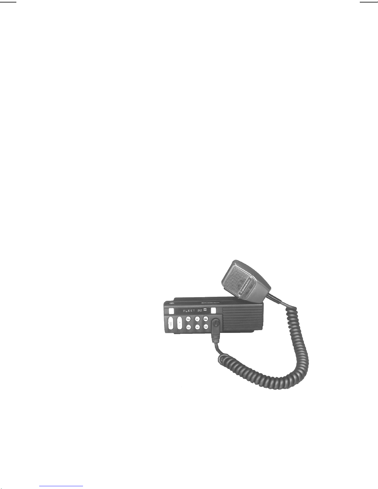
This manual describes how to use the EDACS MDX Mobile Radio. The
MDX is a synthesized, microprocessor-based, high performance simplex
mobile FM radio providing reliable two-way communications in both the
GE-MARC and Enhanced Digital Access Communic ations System (EDACS)
trunking environments. If your MDX is equipped with the Aegis Digital
Voice or Encrypted Digital Voice option, the GE-MARC mode of operation is
no longer availa ble. T he ra dio also o perates with non-tr unke d or conve ntiona l
communications systems. Direct mobile to mobile communication, when out
of repeater ran ge, is also provided.
In an EDACS trunked environment the user selects a communications
system and group. In this mode, audio chann el selection is transp arent to the
user and is controlled via digital communication with the system controller.
This provides advanced programmable features and fast access to
communication channels.
In a GE-MARC trunked environment the user selects a communications
area and group. In this mode, audio channel selection is automatic and is
controlled via tone signalling.
In the Conventional mode, the user selects a channel and directly
communicates on that channel. In this mode, a system refers to a set of c hannels
and a channel is a transmit/receive radio frequency pair.
In either the EDACS or Conventional modes of operation the user can
program some or all of the talk gr oups or channels to transmit and receive Ae gis
Digital Voice or the highly secure Aegis VGE Encrypted Digital Voice. Aegis
is a high quality voice coding algorithm allowing for easy voice recognition.
The exact operation of the radio will depend on the operating mode, the
radio’ s progr amming, a nd the particul ar radio sys tem. Most fea tures desc ribed
in this manual may be enabled or disabled through programming. Consult the
system administrator fo r the particular fea tures that are prog rammed into yo ur
MDX radio.
8
Page 9

CONTROLS, INDICATORS, AND DISPLAYS
The MDX Scan radio contains ten buttons, an eight character DOT
MATRIX display and seven indicators. The MDX System radio contains ten
buttons, an eight charac ter DOT MATRIX display and seven indicator s along
with a twelve button keypad. In addition, there are times when part of the eight
character display is used to display the radio status. Backlighting on buttons
illuminate Digital Legends.
CONTROLS
POWER Momentary push-push switch. Press once to turn
the radio ON. Press again to turn the radio OFF.
VOLUME The momentary switches (auto ramping) VOL-
UME + and VOLUME -. Beeps each time the
VOLUME button is pressed, except wh en a c all is
in process. Hold the button (up or down) to auto
ramp the volume.
MENU Momentary switch. The MENU button is used to
access options on the MDX mobile. Menu operation is coupled with the GROUP/SEL buttons and
the CLR button. To increment from one menu
selection to the next, simply press and release the
MENU button. Press the CLR button to return to
normal operation. The menu choices are listed
below with a description of how to change the
choices (Note: You may have some or all of these
menu choices progra mmed in y our rad io, and t hey
may be programmed in a different order than presented here).
SPECIAL CALL: Press the MENU button until
"SPC CALL" appears in the display. Pressing the
PTT causes the last selected special call to be sent.
To review or change the selection, use the
GROUP/SEL keys to view/change the special call
selection. Up to 25 phone numbers and individual
decode numbers can be stored in the Special Call
menu. While the desired number is displayed,
press the PTT switch to initiate the call.
BACKLIGHT: Press the MENU button until
"BRIGHT" appears in the display. To change the
state of the backlight press the GROUP/SEL + or
- button.
9
Page 10

PUBLIC ADDRESS: Press the MENU button
until "PUB ADDR" appears in the display. Press
PTT to transmit in PA mode.
SCAN ADD/DELETE: Press the MENU button
until "SCAN A/D" appears in the display. Use the
GROUP/SEL- button to step through the group
selections for the current system. Use the
GROUP/SEL + button to change the scan state.
An "S" is illuminated to the right of the display if
the group/channel has SCAN enabled.
ALARM ON/OFF: Press the ME NU button until
"ALM ON" or "ALM OFF" appears in the display.
Press the GROUP/SEL + or - buttons until the
desired state is selected. (Note: This enables or
disables the external alarm; e.g. horn or lights.)
STATUS: Press the MNU button until "ST ATUS"
appears in the display. To review or change the
selection,use the GROUP/SEL keys to
view/change the selection of the status message.
When the desired status is displayed, press the PTT
switch to initiate the status transmission.
MESSAGE: Press the MNU button until "MES-
SAGE" appears in the display. To review or
change the selection, use the GRO UP/SEL keys
to view/change the selection of the message.
When the desired message is displayed, press the
PTT switch to initiate the message transmission.
SCN Momentary switch. Press the SCN button to en-
able or disable scan oper ation. The SCN indicator
will light when scan is enabled. Pressing and
holding the SCN button wh ile on a conventional
channel or an EDACS working channel will permit
the user to adjust the squelch setting from the front
panel by using the VOLUME ramp switch to open
and close the squelch.
10
Page 11
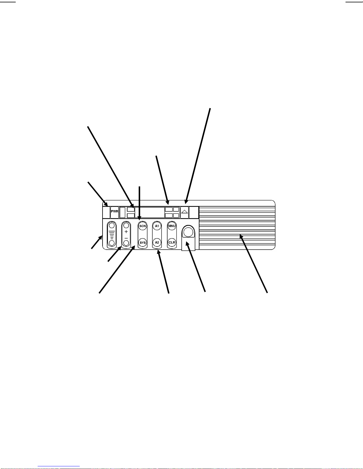
CONTROLS AND INDICATORS
8-Character
Alphanumeric Dot
Matrix LED
allows you to identify
group and system
selections by
descriptive names.
Group/area/system
names, telephone
numbers, menu
options, and status
information are
displayed here.
PWR
MENU
access to functions
and options,
including
pre-programmed
telephone
interconnect and
individual radio calls;
scan add/delete for
modifying the radio’s
scan list (on EDACS
and conventional
systems); and alarm
on/off for the
external al arm option
that uses your horn or
head lights to signal
an incoming call.
Scan Button
button allows
Emergency ID/
Alarm (optional
sends an emergency
alert and identifying
code to the
dispatcher. If no
emergency function
is required, this can
be programmed as a
"HOME" switch.
)
VOLUME
Group/SEL
Ramp
System Switch
through the names of
systems and/or
channels programmed
into the radio,
displaying them on
the Dot Matrix display.
scrolls
Two Flex Keys
give you one-touch
access to the menu or
optional features.
Optional keycaps are
available to identify
the functions of
pre-programmed
buttons, including
Special Call, Scan
Add/ Delete, Public
Address, Home
System/Group,
External A larm , and
display brightness.
Front-Mounted
Microphone
Connector
easy access to the
microphone and
programming
capabilities.
Figure 1 - MDX Scan Radio
provides
Front Mount
Speaker
of audio. An optional
10-watt external
speaker is also
available, for use in
noisy environments.
with 4 watts
11
Page 12
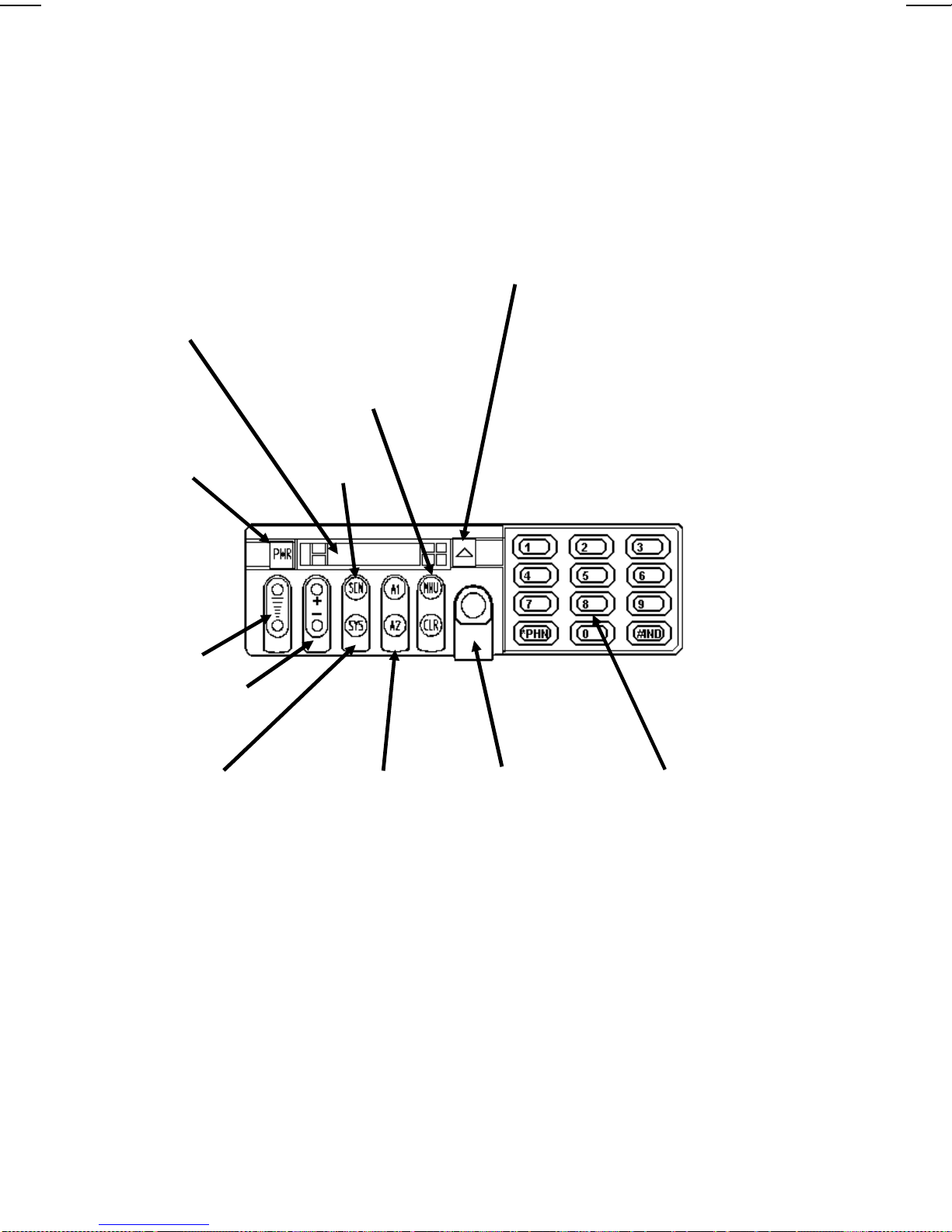
8-Character
Alphanumeric Dot
Matrix LED
allows you to identify
group and system
selections by
descriptive names.
Group/area/system
names, telephone
numbers, menu
options, and status
information are
displayed here.
MENU
access to functions
and options,
including
pre-programmed
telephone
interconnect and
individual radio calls;
scan add/delete for
modifying the radio’s
scan list (on EDACS
and conventional
systems); and alarm
on/off for the
external al arm option
that uses your horn or
head lights to signal
an incoming call.
button allows
Emergency ID/
Alarm (optional
sends an emergency
alert and identifying
code to the
dispatcher. If no
emergency function
is required, this can
be programmed as a
"HOME" switch.
)
PWR
VOLUME
Group/SEL
Ramp
System Switch
through the names of
systems and/or
channels programmed
into the radio,
displaying them on the
Dot Matrix display.
scrolls
Scan Button
Two Flex Keys
give you one-touch
access to the menu or
optional features.
Optional keycaps are
available to identify the
functions of
pre-programmed
buttons, including
Special Call, Scan Add/
Delete, Public Address,
Home System/Group,
External A larm , and
display brightness.
Front-Mounted
Microphone
Connector
easy access to the
microphone and
programming
capabilities.
provides
System Keypad
10-watt external
speaker must be used
with the System model.
12
Figure 2 - MDX System Radio
Page 13

CONTROLS (CONT’D)
SYS Momentary switch. The SYS (S YSTEM) button is
used to select system changes. System may be
incremented by pressing and releasing the SYS
button. Alternately, when the display shows the
System name, the GROUP/SEL buttons may be
used to increment or decrement the system selections. (NOTE: The radio may be programmed with
wrap around on the system selection; this would
allow the radio to switch from the highest to lowest
system with one change instead of ramping all the
way through the list.)
GROUP/SEL Ramp Switch. Th e GROUP/SEL button is used to
increment or decremen t the curren t group/chan nel
selection. It is also used as described above to
increment/decrement the System. In co nventional
mode, these buttons change the channel selection.
CLR Momentary switch. The CLR button is used to exit
from the menu operation, monitor a conventional
channel or end a special/individual call.
HOME/
EMERGENCY
FLEX KEYS
A1, A2
NUMERIC KEYS
1-9, 0, *, #
Momentary switch. The HOME or EMER-
GENCY button is used to select a home system,
group, or channel. The radio may be programmed
to revert to a particular system and/or group/ channel within the selected or home system. I t may also
be programmed to send an emergency message
when pressed and held for approximately one second (either on the selected sy stem/group or on the
Home syste m/ g roup).
The aux buttons are used to access freq uently used
menu selections quickly. They can also be programmed as a HOME or Group/System, no Data
Toggle button, External Alarm, Public Address,
PriVaT e or Group ID entry.
On System radio, the twelve button keypad permits
telephone interconnect and DTMF overdial as well
as Group and Individual ID call entries.
13
Page 14
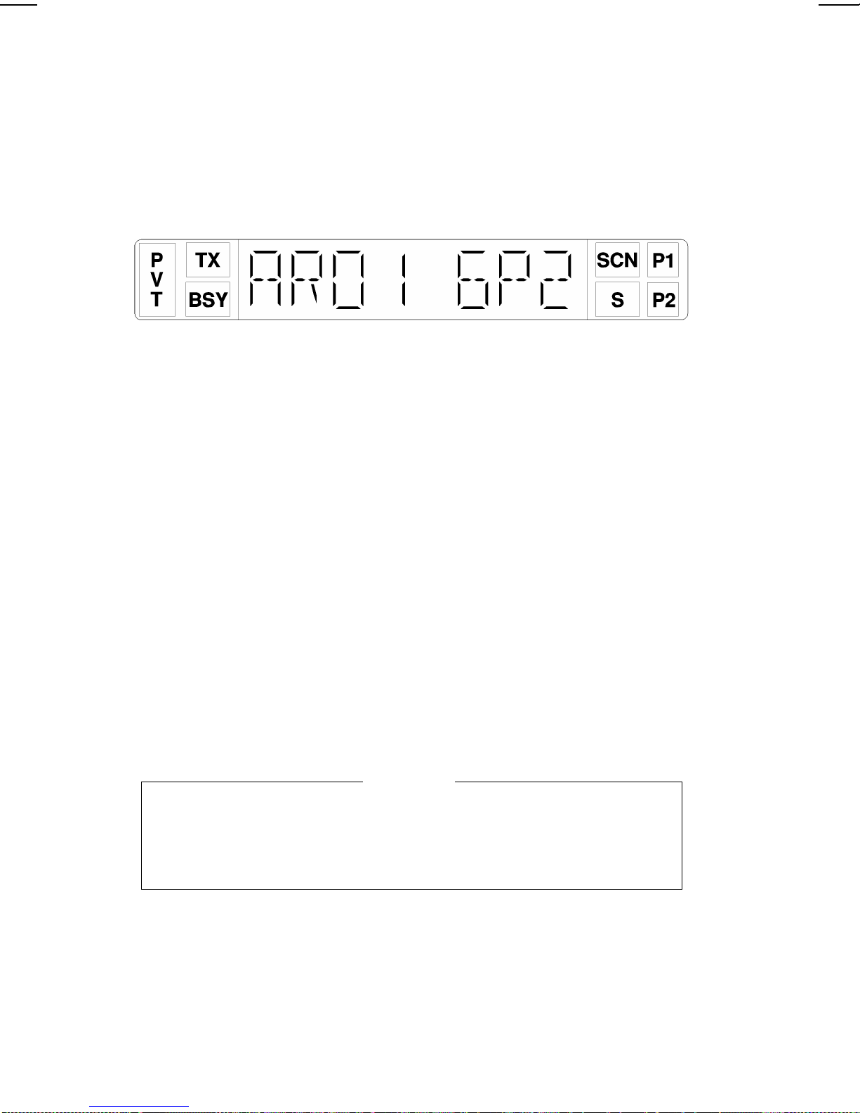
DISPLAY INDICATORS
The radio’s display is shown below. The character line is used to display
system or ar ea an d g rou p or chann el na mes an d als o op erat io na l mes sa ges t o
the user. The line contains eight Dot Matrix LED characters. The 7 status
indicators are used to show the various operating conditions of the radio.
Figure 3 - Sample MDX Display
TX On indicates the radio is transmitting.
BSY Lights when a group is active (trunked system) or
when a channel is busy (conventional system).
Flashes when a ca ll is queue d on a trunked sy stem.
SCN ON indicates scan is enabled.
S ON indicates group/channel in scan list.
P1 ON indicates selected channel is a priority channel
(conventional only).
P2 ON indicates selected channel is a priority 2 chan-
nel (conventional only).
PVT ON indicates selected channel has been pre-pro-
grammed for Aegis operation. Flashes indicates
receiving an encrypted digital voice call.
NOTE
In EDACS operation the P1 & P2 indicators can be programmed to flash
when the radio has received an individual call. Display shows "C* to
show receipt of I-CALL.
DISPLAY ALPHA INDICATORS
The radio is capa ble of displayin g status indicato rs in the alph a display.
Some of these messages will use the entire display while others use only two
or three characters. When the short message is displayed it may be on the right
14
Page 15

or left of the display (PC programmable). It is separated from the normal
information with an indicator such as an asterisk ("*").
Full Length Indicators
**INDV** Displayed when your unit receives an individual
call from another unit.
ID##### If programmed, displayed when your unit receives
an individual call where ##### is the unit ID of the
calling radio. (Note: If the ID is in your Special
Call list, you may choose to show an 8 character
name instead of the number.)
PHN CALL Displayed when your radio receives a telephone
call from the trunked system.
DATACALL Displayed when your radio is involved in a data
call.
*NO DATA D isplaye d when yo ur r adio is in the data disa bled
state.
* NC * Displayed when no control channel is fo und on a
trunked system.
ALL CALL Displayed when receiving a system wide call.
*AGENCY* Displayed when rec eiving an Agency Call.
*FLEET* Displayed when receiving a Fleet Call.
EMERGNCY Displayed steady when oper ator de clares an emer-
gency (optional), flashes when another user de-
clares an emergency.
BOOT DSP Displayed at power on in radios equipped for Aegis
operation. Indicates initialization of Digital Voice
Module.
LOAD KEY Displayed when VGE encryption keys are being
uploaded to the Digital Voice Module.
Abbreviated Indicators
F* Displayed on radios defi ned in the PC pr ogrammer
as supervisory when the trunked system is in fail-
soft mode. (Note: In failsoft mode, trunked dis-
patch operations is fully operational but
interconnect may not be possible.)
15
Page 16

C* Displayed when an individual call has been re-
ceived and not answered. By selecting Special Call
in menu mode, the call can be recalled for return at
a later time. (Note: The call is not saved through
a power cycle.)
E* Displayed when an active voice call on a trunked
system is in an emergency state.
ALERT TONES
The EDACS MDX radio generates a set of unique alert tones to indicate
operating status. The following section identifies and describes the alert tones
used in the MDX radio for Conventional, GE-MARC, and EDACS
applications.
ALL APPLICA TIONS
SELF CHECK
TEST ALERT
One beep is sounded after the radio is turned on to
indicate that the radio has passed the self diagnostic
test. Optional in PC programmer.
EDACS APPLICA TIONS
CALL
ORIGINATE
ALER T
If programmed, a short to ne is so unde d whenever
the Push-To-Talk (PTT) button is keyed and the
radio has acquired a channel. This tone indicates
the user may be gi n c om munications.
AUTOKEY When the PTT is keyed to place a call on the
system, but the PTT is released before getting to
the channel (e.g. a queued call), the radio automatically keys on the channel when it gets the assignment. The radio generates a long beep and holds
the transmitter keyed for two seconds. Pre ssing the
PTT button keeps the channel and sends the message before this two second time-out has expired.
OUT OF RANGE/
SYSTEM
INOPERATIVE
A single low pitched tone will sound immediately
after the PTT switch is keyed indicating the radio
is out of range of the repeater. The radio tries to
place the call for a short period (3 seconds) after
the initial attempt. The radio generates a second
low pitched tone when it gives up trying to p lace
the call. The system is off the air or the radio needs
servicing when the radio is within calling range,
and these tones are heard.
16
Page 17

CALL RECEIVED If programmed, a single alert tone sounds when a
group call is received and a two tone alert (one high
followed by one low tone) is sounded for an indi-
vidual call.
CALL DISABLED
ALERT
You will hear a continuous low pitched tone when
your radio is set to an Rx (decode) only
group/channel and you press PTT on the micro-
phone. This tone indicates that you are not allowed
to place a call on this setting.
CARRIER CONTROL
TIMER
The Carrier Control Timer alert is a low pitched
tone you will hear whenever you have kept the
PTT button continuously pressed for a pre-pro-
grammed leng t h of t ime. Four warning beeps pre-
ceed the tone and transmitter shutdown. The
transmitter shuts down when the steady low
pitched tone starts, interrupting communications.
To maintain communications, release and re-key
the microphone. This resets the timer and turns the
transmitter back on. The CCT is a built in precau-
tion against extende d use of the system.
EDACS ALERT TO NE SETS
There are two EDACS alert tone sets: single and continuous. The EDACS
MDX radio can be programmed to use either set .
Single Alert Tones
CALL QUEUED If one short, high pitched tone sounds after the
transmitter is keyed, it indicates the system has
placed the re qu es t i n a qu eue. Thi s tone sou nd s at
both the transmitting and receiving end that a call
is forthcoming. If the PTT is unkeyed while in the
queue, the radio will automatically key push-to-
talk when a channel becomes available (see
AUTOKEY).
SYSTEM BUSY I f you key the PTT bar and hear three sh ort, me-
dium pitched tones, it indicates that the receiving
party is alre ady on the syste m or the system is busy
and its queue is full. Y ou must re-key later to access
the system.
CALL DENIED A single low pitch beep will sound when the PTT
switch is keyed and the request is denied by the
17
Page 18

system. This happens if the unit is an invalid user
or if the unit is requesting an unavailable service.
Continuous Alert Tones
CALL QUEUED If you hear two short, high pitched beeps after you
key the microphone, the system has placed your
request in a queue. The tones sound at both your
transmitting unit and the receiving unit(s). This
indicates to the receiving unit(s) that they will
receive a call shortly . These tones will repeat every
half second at the caller’s radio until Push-To-T alk
is released. If you unkey the microphone wile in
queue, your radio will autokey when a channel
becomes available [Automatically key (push-totalk), see AUTOKE Y].
SYSTEM BUSY If you key the microphone and hear four short, low
pitched beeps, the receiving party is already on the
system or the system is busy and its queue is full.
The busy tone sequence is repeated as long as you
continue to press the PTT switch. Y ou must release
and re-key the PTT switc h to access the system.
CALL DENIED If you hear five long low pitched tones when you
key the microp hone , yo ur re que st ha s bee n de nied
by the system. this happens if you are an invalid
user or if you are requ esting an unavailable servic e.
END OF "CALLBACK" After receiving a Multi-Group Decode, Scan or
Individual Call, you will have a pre-programmed
period to respond back to the caller. At the end of
this period, the radio will sound two short tones to
indicate a return to normal operation, and the received call can no longer be answered directly.
GE-MARC APPLICA TIONS
CALL RECEIVED
ALERT
If programmed, a single alert tone sounds when a
group call is received and a two tone alert (one high
followed by one low tone) will sound for an individual call.
CALL
ORIGINATE
ALERT
WAIT will momentarily be displayed when a call
is placed; then a three-tone alert is sounded to
indicate the call origination is complete. This indi-
18
Page 19

cates a channel was acquired and is ready for
normal conversation .
INVALID CALL
ORIGINATE
ALERT
A low frequency tone is so unded for one second
immediately after pressing PTT and the display
does not show WAIT. This indicates a call was
attempted within a group that is not enabled for call
originate or an invalid dispatch overdial call was
attempted.
SYSTEM TONES A low frequency tone is so unded for one second
after attempting to place a trunke d ca ll a nd BUSY
will be displayed. This indicates the GE-MARC
system is busy . If the "Ca ll Retry" option has be en
enabled through programming, the radio will retry
at 5 second intervals, up to 15 times unless END
is pressed, a channel is acquired, or an out-of-range
condition occurs.
OUT OF RANGE
ALERT
If NO SVC is displayed and five beeps are sounded
after attempting to place a trunked call, then the
radio is out of ra nge of th e GE-MAR C sys tem. I f
the beeps sound when the radio is within known
range of the system, th e rad io may need servicin g.
If the "Call Retry" is active, the radio will try the
channel at twenty second intervals for five min-
utes.
CARRIER
CONTROL
TIMER
(GE-MARC and Conventional ) A pulsed tone
signal is sounded after PTT is pressed continu-
ously for a pre-programmed time. After nine sec-
onds of pulsin g the a lert ton e, the radio unke ys the
transmitter and communications are interrupted.
While the tone is pulsing, the user can release and
press PTT again to reset the timer and resume the
conversation. In the conventional mode, the radio
unkeys and beeps until PTT is released.
SYSTEM TONES The GE- MARC radio may generate other system
tones to alert the user of custom programmed
events. Contact your GE-MARC system operator
for details about these alert tones.
19
Page 20

OPERATING NOMENCLA TURE
TRUNKED OPERATION (EDACS OR GE-MARC)
Trunked operation refers to the use of a set of radio frequency channels
by multiple user groups. Users may place and receive calls to single or multiple
users without being monitored by other user s (or group) on the system.
CONVENTIONAL OPERATION
All radios on a conventional system operate in one of two modes: repeated
or talk-around. T alk-around (also referred to as "direct mode") provides a direct
radio-to-radio short-range communications link. It is intended to maintain
communications outside of the main system coverage area. Trunked features
(such as call queueing and system scan) are not available in conventional mode.
DEFINITION OF TERMS
System The term system refers to the particular group of
station repeaters and set of group/special calls providing service to the radio. Radios can be preprogrammed to work in different systems by changing
the systems selection or through wide area roaming.
Group Or
Subfleet
A group of users share the same preprogram-med
group identification number in their radios. All
radios in the same group receive dispatch calls
placed by any one radio in the group.
Fleet A fleet of users consists of multiple groups (sub-
fleets). Radios can be preprogrammed to make
fleet calls to simultaneously access multiple user
groups.
Agency An agency is composed of multiple fleets. Radios
can be pre-programmed to initiate agency calls to
access multiple fleets.
Individual Call Every radio in the system has been assigned a
preprogrammed, unique individual identification
code. A radio can be programmed to individually
call another particular radio from the Special Call
Menu.
20
Page 21

Wide Area System Operation (Optional)
This function applies when your systems are networked together in a
multi-site configuration. In this mode, your calls are automatically routed to
the proper system. You may notice a delay when you press the PTT button
while the system is connecting the correct sites. The BSY indicator will be on,
indicating you are on the voice channel. In this mode, you can release and press
PTT again to override the delay. This gets you onto the system, but does not
guarantee that everyone will hear the message.
When in the multi-site mode, your radio may be programmed to look for
alternate s ys tems when you g o out of range of the cu rren tly se lected sys tem.
If an alternate system is found, the radio locks onto the system and
automatically selects the correct information for this new system. Alternate ly,
the radio may be programmed to revert to a conventional channel when out of
range of the trunked system.
Each trunked system may also have a priority trunked system associated
with it when set to a system with a priority system programmed, the radio
periodically checks for the priority system. If found, it automatically switches
to that system. The timer is reset every time the PTT button is pressed to avoid
interrupting a conversation.
ProSound
The radio may be pro grammed for ProSou nd system scan op eration for
multi-site applications. ProSound scanning is an enhanced replacement for
wide area system scanning. This algorithm insures that the radio continually
receives high quality audio. When the selected system degrades to a
pre-progra mmed leve l, the rad io begins se archin g for the be st adja cent syst em
on a part time basis. Once a better system is found, th e radio changes to the
new system and sounds a tone. Should the control channel be lost completely,
the radio will scan the adjacent systems until a suitable one is found.
Telephone Interconnect
This feature allows you to initiate preprogrammed Special Calls or receive
telephone calls through your radio if the system is configured for this oper ation.
BASE/UNIT OPERATION
This pre-programmed option is used in some fleets so units can only hear
and talk to a base dispatch unit, not to other radios in the group. In this mode
of operation, when a radio in a particular group is talking to the base dispatch
21
Page 22

unit, all other radios in that group will receive a "System Busy" tone if they
try to access the system.
OPERATING THE RADIO
TURNING THE RADIO ON
1. Push the POWER sw itch. The d isplay sh ows the group alph a name
once power up is complete. When powering up, the last selected
Group or Channel should be displayed unless the radio is pro-
grammed for a pre-programmed power up System/ Group. The radio
optionally generates a beep once the power up sequence is complete.
On radios with Multi-site features enabled, the radio automatically
logs onto the system once power up is complete.
2. Set the volume using the VOLUME RAMP button. A short beep
sounds each time the VOLUME button is pressed. The beeps will not
sound if a call is being received.
SELECTING SYSTEM/GROUP/CHANNEL
Use the GROUP/SEL and SYStem controls to select a different Group,
System, or Channel.
Group Selection
1. If the unit is in Menu Mode, press and release the CLR button to
return the radio to normal operation.
2. Press the GROUP/SEL + or - ramp button until the desired Group
name appears in the alphanumeric display. A tone sounds each time
the Group name changes (unless a call is being received).
System Selection
1. If the unit is in Menu Mode, press and release the CLR button to
return the radio to normal operation.
2. Press and release the SYS button to bring up the currently selected
system. Press and release the SYS button again to increment the
System selection.
3. If you want to ramp the system choices up or down, press the
GROUP/SEL + or - ramp button while the system name is displayed.
22
Page 23

A tone sounds each time a System name changes. On units with
Automatic Log in for Multi-site Operation, the radio tra nsmits briefly
after a system change.
Channel Selection (Conventional System)
To select a different channel when you have selected a conventional
system:
1. Press the GROUP/SEL + or - ramp button until the desired channel
name appears in the alphanumeric display. A tone sounds each time
the channel name changes unless the BSY indicator is on.
FRONT PANEL SQUELCH ADJUSTMENT
The squelch setting of the radio can be adjusted by the user through the
front panel controls. There are a total of 256 steps used internally to the radio
for squelch level adjustment.
With the radio on a conventional channel or an EDACS working channel,
press and hold the SCN button. Then use the VOLUME ramp button to open
and close the squelch. After setting the squelch to the desired setting, release
the SCN button to return the radio to normal operation.
INTERNAL/EXTERNAL SPEAKER
When the Internal/External Speaker Option PMSU5A has been installed
along with an external speaker, the operator can select either speaker one of
two ways.
1. Set the ON/OFF switch on the option box to the ON position to select
the external speaker and disable the internal speaker. Place in OFF
position to select the internal speaker only .
OR
1. Pres s the A1 or A2 button (pre-programmed) to select the external
speaker and disable the internal speaker. Press the A1 or A2 button
again to select the internal speaker only.
MICROPHONE PUBLIC ADDRESS OPERA TION
When the Public Address Option PMSU5A has been installe d along with
an external speaker, the operator can use the microphone as a public address
system.
23
Page 24

1. Make sure the radio is turned ON.
2. Press the MNU button until PUB ADDR appears in the display . Press
the PTT switch to transmit the microphone audio to the external
speaker.
3. When the P A operation is completed, press the CLR button to return
to normal operati o n.
OR
1. Make sure the radio is turned ON.
2. Press the A1 or A2 button (p re-program med). When PUB ADDR
appears in the display press the PTT switch to transmit the micro-
phone audio to the external speaker.
3. After the PA operation is completed, press the A1 or A2 button to
return to normal operation.
EDACS TRUNKED OPERATION
PLACING A TRUNKED DISPATCH CALL
To sen d a me ssage on a trunked system, proceed as follows:
1. Select the System and Group you wish to transmit on.
NOTE
If the group you wish to transmit on is not in the list, a properly
programmed System Model MDX has the capability of operating on a
user selected gr oup ID.
2. Press and ho ld down the PTT button.
3. You will hear a short beep (unless the radio is programmed to mute
the beeps) indicating that you have access to the system. W hen you
hear the beep, you may begin your message. (Note: If you hear two
or more tones or a continuous tone, the system may be busy, your
request has been placed in queu e, or your call re quest has bee n denied
for some reason. Re fer to ALERT TONES for more details.)
4. After you have finished your call, releasing the PTT button ends the
call automatically.
24
Page 25

NOTE
In rare instances, several low pitched, fast "chirps" will be heard before
the Call Originate tone sounds. This is caused by your radio
automatically re-trying to gain access to the system after the first
attempt failed (Auto-Retry). This normally occurs in fringe areas and
in heavily used systems. The Auto-Retry is one of the f ea tures utilized
by the radio system to provide reliable communications under adverse
conditions.
MANUALLY ENTERING A GROUP ID ( S yste m Model Only)
1. Press the A2 button and observe "GID ENTR" in the display
2. Enter the group ID number using the numeric keypad. (Valid range
1-2047).
3. Pres s the A2 button again and observe "GID nnnn" (where nnnn is
the entered number) in the display. This new group will replace the
first group in the list.
NOTE
It is recommended that a null group be programmed into the first
location initially. This will avoid overwriting a desired group from the
list unintentionally .
RECEIVING AN EMERGENCY MESSAGE
From The Select ed G roup
When an emergency is received from a member of your selected group,
"EMERGNCY" flashes on your display.
If an emergency call is made, "E*xxxxxx" (where xxxxxx is the balance
of the group display) will flash in the display until the call is complete.
When an emergency transmission is received from a member of your
selected Group or System; the "E*" portion of the display will flash, the BSY
indicator will come on, and a tone sounds. When this occurs, follow your
standard emergency procedures. The emergency display remains on until the
emergency is cleared.
25
Page 26

From A Scanned Group
When you receive an emergency call from a scanned Group (scan
operating), the display shows the scanned Group’s name with the first two
characters replaced by the emergency indicator (typically "E*"). The BSY
indicator comes on, and you hear the Emerg ency tone. The display will flash
until the BSY indicator goes out and the radio returns to normal operation.
SENDING AN EMERGENCY MESSAGE
To send an Emergency call to the selected (or Home) System/ Group,
proceed as follows:
1. Press and release the HOME/EMERGENCY button (holding it
pressed for approximately one second). The radio continuously dis-
plays "EMERGNCY" (unless programmed off). A message with
your ID is also sent to the dispatcher declaring an emergency. You
will be given highest priority for voice communication.
2. Press the PTT button and wait for the channel-available tone. Speak
into the microphone in a normal voice. All audio and displays are
restored to norm al.
3. Release the PTT button when the transmission is complete, a nd listen
for any reply. The TX indicator will go out when you release the PTT
button.
CLEARING AN EMERGENCY
If your radio has been programmed as a supervisory unit, you may clear
emergency calls . When the emergency is no longer in effect, the emergency
call may be cleared as follows:
1. Press and hold the CLR button.
2. Press and release the Home/Emergency button. The EMERGNCY
display goes off.
3. Releas e the CLR button.
SPECIAL CALLS
The Special Call feature within the Menu operation allows you to make
calls to individual radios, telephone interconnect Calls and/or System All Calls.
26
Page 27

Placing A Telephone Interconnect Call (On Systems Equipped With In terconnect Hardware)
1. Make sure the radio is turned ON, and the proper System has been
selected. Press the MENU button until the name SPC CALL appears
in the display . Press the GROUP/SEL + or - buttons until the desired
name appears in the display. The number may be entered manually
on the 12 button keypad of the System Model radio.
2. Press the PTT bu tton moment arily and rel ease for a pre-prog rammed
number. Press the "*" key for a manually entered number on the
System Model radio.
3. The radio automatically transmits the pre-programmed number
stored in the radi o’s memory. The system d ials the nu mber and th e
ringing tone is heard on the radio. When the landline party answers,
you may speak t o them by pressing the PTT butt on and talk.
NOTE
Your MDX radio is capable of simplex (o ne way) conversation only.
The person y ou are talk ing to can he ar yo u ON LY when you ha ve the
PTT button pressed. You can hear the person on the telephone ONLY
when the PTT button is released.
If you leave the PTT button released for too long, the system will send
three beep s. When you he ar these be eps, you hav e five seco nds to press
the PTT button before the call is automatically terminated.
To terminate the call, momentarily press the CLR button or hang up
4.
the microphone.
Answering A Telephone Interconnect Call
1. Receiving a telephone interconnect call is much like receiving an
individual call (refer to RECEIVING AN INDIVIDUAL CALL).
When the telephone call is rec eived, the r adio displays PHN CALL.
2. To terminate the call, momentarily press the CLR button or hang up
the microphone.
3. If you were out of the vehicle when the call came in, the display will
show "C*" or "*C" or P1 & P2 indicators will flash to indicate that
a call was rece ived. If you select SPC CALL from the menu, the " C*"
or P1, P2 indicator, will go away if the call was a phone call. See
RECEIVING AN INDIVIDUAL CALL for more de tail.
27
Page 28

Placing A Spe cial Call To Another Radio
1. Make sure the radio is turned ON, and the proper System has been
selected. Press the MENU button until the name SPC CALL appears
in the display . Press the GROUP/SEL + or - buttons until the desired
name appears in the display. The radio ID may be entered manually
if using the MDX System Model radio.
2. Press the PTT button and wait for the channel available tone before
talking.
3. When completed, release the PTT button and listen for any reply.
4. When your call is finished, press the CLR button or return the
microphone t o t he ho okswi tc h. Th e pre vio usly se lec ted Grou p name
appears on the display.
Receiving An Individual Call
When you receiv e an Individual Cal l (call directe d only to your radio) , the
display changes to one of the following displays :
1. "*INDV*"
2. "IDxxxxx", where XXXXX is the numeric ID of the calling radio
3. "ALPHA", where ALPHA is the alpha name of the calling radio
Receiving an Individual Call will also cause the BS Y indicator to turn
on. After the transmission, the BSY indicator will go out. The display
will continue to show the above until the pre-defined time-out for
calling back expires. During this callback period, press the PTT
button to return the call. If the call is not returned before the time has
expired, the display will return to the Group display with a "C*" at
the left side or a "*C" at the right side of the display or P1, P2
indicators flashing. This indicates a call has been received. Pressing
CLR will cause this indicator to go out. The radio will retain the ID
in the Special Call list until the radio is powered off or another call is
received.
GROUP SCAN OPERATION
You may program your radio to scan a number of Groups for activity .
28
Page 29

Adding/Deleting To/From Scan
To add a Group to Scan,
1. Press the MENU button until SCAN A/D is displayed for menu
operation.
2. Pres s the GROUP/SEL (-) button until the GROUP name is dis-
played.
3. Press the GROUP/SEL (+) button until the desired level is displayed
(NONE or S).
4. Press the CLR button when complete to return to normal operation
or menu operation.
If your radio has one of the auxiliary keys pre-programmed to edit the
SCAN list, the list may be changed by using the GROUP/SEL buttons to
display the GROUP name, and then pressing the auxiliary key until the desired
level is displayed.
Starting Or Stopping Scan
1. Press the SCAN button until either the "SCN" indicator goes off or
on.
NOTE
1. The radio will remember the scan state th rough a power cycle
unless programmed with a predefined power up state.
2. The radio ma y be progra mmed to s top scanni ng when the microphone is removed from teh hookswitch.
3. When the radio is programmed, a FIXED SCAN list can be
specified. If this is done, the SCAN list cannot be changed.
RECEIVING A CALL
When a call is received by the radio, the call is decoded. A single alert tone
will sound indicating a group call has been received or a two tone alert will
sound if an individual call has been received. The display will show the system
or area and group when receiving a group call and the system or area and
29
Page 30

individual decode when an individual call is received. If the calling party’s
name is not found, their five digit ID will be displayed instead.
If a dispatch call is desired, simply pick up the microphone and press the
PTT to transmit to the caller.
ENDING A CALL
The call can be terminated in one of three ways:
METHOD 1: Press CLR.
METHOD 2: A system disconnec t or time out occurs. Du ring a dispatch
call the time out occurs after 6 seconds of channel silence.
During an interconnect call the time out occurs after 30
seconds of channel silence.
METHOD 3: Returning the Micr ophone to the hang-up bracket (enabled
through progra mming).
NOTE
If a channel discon nect occurs before the c onversation ended, the call
must be initiated again. To avoid confusion it is recommended that a
procedure be set up so that the originator of the ca ll is the one designated
to re-establish communications. Two or more operators originating a
call simultaneously may acquire two different channels making
communication impossible.
CONVENTIONAL FAILSOFT OPERATION
In the unlikely event of a failure of the EDACS System, communications
may take place in conventional failsoft mode. Your radio will be automatically
directed to a communications channel set up for this purpose. During this mode
of operation, your control unit displays "CONV FS" in the alphanumeric
display. You will also notice increased activity on your channel during
conventional failsoft operation, so be careful not to transmit until the channel
is clear.
Operation during conventional failsoft will be the same as operation on a
conventional system, except you cannot selec t a communications channel, or
use Emergency or Special Call. When trunking is restored, the radio
automatically returns to normal operation.
30
Page 31

NOTE
Emergency and Special Call are not operational during conventional
failsoft. Also, the GROUP control will not opera te.
MOBILE DATA TERMINAL INTERFACE (OPTIONAL)
Your MDX radio is capable of interfacing with a Mobile Data
Terminal/Computer Host (EDACS ONLY). When placing or receiving data
calls, the MDX displays "DATACALL". When "DATACALL" is present,
voice calls are disabled. You will miss all voice calls made to the radio when
data is being exchanged.
NOTE
Optional interface cables are required when oper ating with the Mobile
Data Terminal/Computer Host.
You can stop transmission and reception of data using any of the following
methods:
1. Remove the microphone from the hookswitch.
2. Hold the CLR button and press PTT. A high pitched beep will be
heard. Release the CLR button.
3. Declaring an Emergency (not to be used unless an actual emergency
condition exists).
4. A group or system change.
When in the no-data mode, the radio displays "*NO DATA". This will
remain displayed until the no-data mode is cleared by one of the following
(depending on how it was activated):
1. Replace the microphone into the hookswitch.
2. Repeat the CLR-PTT sequence.
3. Use the CLR-PTT sequence during the emergency to enable data.
SCAN LOCKOUT MODE
Following the transmission or reception of a data call, if scan is enabled,
scanning will stop temporarily (duration pre-programmed). During this time
31
Page 32

the scan LED will flash to indicate that scan is enabled but temporarily
suspended. This mode is normally exited when the pre-programmed time
expires; however, the following actions will terminate the scan lockout mode
before the timeout is completed.
• The CLR button is pressed.
• PTT is presse d.
• A group or system change.
• Entering phone call mode.
• A new emergency assignment has been received.
• PTT pressed in P ubli c Addre ss Mode .
• An emergency declared or cleared.
• Microphone removed from hookswitch (off-hook).
• Receiving an individual or phone call.
• Receiving Agency , Fleet or System All Call.
• Pressing the SCN button to turn scan on or off.
DATA LOCKOUT MODE
The data lock mode is a pre-programmed mode when the radio will not
respond to any data ch annel assignments and prevents re ceive data calls from
interrupting voice calls. Transmit data calls will still be initiated when needed
by the operator . After a pre-programmed time, the radio will respond to receive
data calls; however , the following conditions will clear the data lockout mode:
• The CLR button is pressed.
• Transmitting a data call.
• Changing a system.
• An emergency.
• Pressing PTT while in Public Address mode.
• Turning scan on with the SCN button.
STATUS OPERATION
Status operation permits the transmission of pre-programmed status con-
ditions to the EDACS site. The status can be sent in two ways.
1. Pres s th e MNU button until "STATUS" appears in the display. Us e
the GROUP/SEL buttons to step through the selections.
2. When the desired status is displayed, press the PTT switch to send
the status to the site or stored in the radio memory where it can be
polled by the site at a future time. If the site does not receive the status
properly, the radio will sound a low pitched tone.
32
Page 33

3. Press the CLR button to return the radio to normal operation.
OR
1. Press the A1 or A2 button (pre-programmed). "STATUS" appears in
the display. Use the GROUP/SEL button to view/select the status
to be sent.
2. Press the PTT switch to send the status to the site or to be stored in
the radio memory where it can be polled by the site at a future time.
3. Press the A1 or A2 button to return to normal operation.
MESSAGE OPERATION
Message operation permits the transmission of pre-programmed mes-
sage(s) to the EDACS site. The message can be sent in two ways.
1. Press the MNU button until "MESSAGE" appears in the display . Use
the GROUP/SEL buttons to step through the selections.
2. When the desir ed messag e is displa yed, pr ess the PTT switc h to send
the message to the site. If the site does not receive the message
properly, the radio will sound a low pitched tone.
3. Press the CLR button to return the radio to normal operation.
OR
1. Press the A1 or A2 button (pre-programmed). "MESSAGE" appears
in the display. Use the GROUP/SEL button to view/select the
message to be sent.
2. Press the PTT switch to send the message to the site. If the site does
not receive the status properly , the radio will sound a low pitched tone.
3. Press the A1 or A2 button to return to normal operation.
DYNAMIC REGROUP OPERATION
Dynamic regroup operation permits multiple talk groups (up to eight) to
be added to a radio via the system manager. The radio must be pre-programmed to respond to regrouping. Dynamic regrouping will not be ac tivated
in a radio until an activation message is sent by the system manager. Each
radio that receives and acknowledges the regrouping instructions is successfully regrou ped.
33
Page 34

Emergency Operation
If the pre-pr ogrammed groupset on the curre ntly selected system conta ins
an EMERGENCY/HOME group and the ra dio is in dynamic regroup, the ra dio
will exit dynamic regroup and declare the emergency on the HOME group. If
no EMERGENCY/HOME group is present, the radio will declare the
emergency on the currently selected dynamic re group group.
AEGIS OPERATION
NOTE
Each channel or talk group (EDACS) ca n be programme d for ANALOG
Voice, Aegis Digital Voice, or Aegis VGE Encrypted Digital Voice mode
of operation by programming the "KEY" variable
When programmed "DIS", a channel or talk group will only operate in
the ANALOG mode. ANALOG voice calls can be eas ily monitored by
unauthor i z ed persons.
When programmed "DIG", a channel or talk group will only transmit
Aegis Digital Voice. Aegis Digital Voice and ANALOG Voice calls can
be received.
When programmed "1-6", a channel or talk group will transmit Aegis
VGE Encrypted Digital Voice. Valid cryptographic keys must be loaded
into the MDX using the Universal Key Loader. The "PVT" icon
(indicating encryp ted mod e is on) can be turned on and off usin g one of
the AUX keys or by chosing "FORCED" as the m ode of ope ration in the
programmer.
VOICE MODES
Each system (trunked or conventional) in the radio can be programmed
for Aegis commun ications. Aegis pr ogrammed syste ms have two (2) differen t
voice mod es: cle ar (an alog) a nd digita l. The voice modes are prog rammed on
a per-group basis within each trunked system and on a per-channel basis within
each conventional system . A radio m ust be equipped with the encryp t/decrypt
option before it will operate in Aegis mode.
TRANSMIT/RECEIVE MODE COMPATIBILIT Y
FOR AEGIS OPERATION
GROUP/CHANNEL
PROGRAMMING
CLEAR
RECEIVE
DIGIT AL
RECEIVE
(TRANSMIT)
CLEAR Yes No
DIGITAL Yes Yes
34
Page 35

NOTE
Conventional Aegis requires Ch annel Guard on the channel to operate
correctly.
CLEAR MODES
In clear mode the radio transmits and receives only analog voice signals.
These analog signals are non-digitized and non-encrypted. Clear mode
transmissions can be easily monitored by unauthorized persons. Groups or
channels programmed for clear operation cannot transmit or receive Aegis
digital messages.
AEGIS DIGITAL MODE
Aegis digital mode allows the radio to transmit and received digitized
voice signals. Aegis digital signals provide improved weak signal
performance and they cannot be easily monitored with a standard receiver.
Groups and chann els programmed for Aegis dig ital operation transmit only
digital signals.
Message trunked group calls and individual calls will be answered back
in the mode in which they were received, assuming the call or hang time is still
active. Individual, phone, all and emergency calls will be transmitted clear if
digital mode is disabled or inoperative.
1. If receiving an analog message trunked call, the radio will respond in
analog mode during the hang time on the working channel.
2. If receiving an analog I-Call, the radio will respond in analog mode
during the call back time.
3. When using the "call back" feature to respond to an I-Call the call
will be transmitted in the mode in which it was received.
Scanned Group Calls
Receiving a scanned group call is the same as receiving a selected group
call. During the scan hang time, if the radio was programmed for autoselect,
it will transmit back in the same mode in which the call was received. For
example, if a clear group is entered in the scan list, it will only receive clear
calls. If the same group was available in digital and entered in the scan list, it
can receive clea r and digital ca lls, provided autoselect was progra mmed in the
radio. The user can select transmitting on the scanned or selected group. If a
35
Page 36

group is entered in the scan list more than once and in different modes (clear
or digital), only the first occurrence of the group will be used.
CONVENTIONAL OPERATION
Outside Address
The same outside address (works similar to Channel Guard operation)
must be programmed in the transmitting and receiving radios when Aegis
digital operation is enabled. If address is not correct, the radios will not
communicate.
Channel Guard
Channel Guard encode is transmitted on analog, clear channels only.
Channel Guard decode will operate on either a clear or digital channel. The
exception is when GE•STAR signaling is us ed (see GE•STAR pa ragraph).
GE•STAR
When GE•STAR is programmed on a private channel, the radio will
transmit GE•STAR in clear mode and then switch to private for the voice
portion of the call. If GE•STAR is sent with C hannel Guard, then both are
sent in clear mode and then radio switches to private mode. Emergency
GE•STAR data burst is transmitted in clear mode.
GE-MARC OPERATION
PLACING A DISPA TCH CALL
1. Select the desired sy stem or area and group.
2. Press PTT.
3. The display changes from the selected system or area and group
display to WAIT while the radio is acquiring a repeater.
4. The radio sounds a three-tone alert signal when the communications
channel is acquired.
5. If the radio is out of range of the selected system, 4 short and 1 long
beep will be heard and NO SVC will be displayed for approximately
20 seconds. While NO SVC is displayed, no attempts can be made
to place a call. If a ne w area is s elected NO SVC turns off and the
36
Page 37

call can now be attempted in the new service area. If all available
repeaters are busy when the call is attempted, 1 long beep is heard
and BUSY is displayed. If the call retry option has been enabled
through programmin g, RETRYING displays instead of the BUSY
message.
6. The Selected area and group is displayed again once the call is
completed.
RECEIVING A TRUNKED DISPATCH CALL
1. You will hear a beep each time you have an incoming call (unless the
radio is programmed to mute the beep). A single beep indicates you
are receiving a group call. Two beep s (high-low) indicate you are
receiving an individual call. You will then hear the voice message.
You can answer the call by pressi ng the PTT button.
NOTE
In some modes of operation such as an agency call, fleet call, or
individual call, you must answer the caller within several seconds. If
not, two short beeps will sound, the call will be terminated, and normal
system operations will resume.
2. When you hea r a high pitch ed beep, someo ne in your syst em has tried
to call you, but the call was queued because the system is busy. T hese
beeps let you know you will receive a call shortly.
SPECIAL CALLS
The Special Call feature within the menu operation allows you to make
calls to individual radios, Telephone Interconnect Calls and/or System All
Calls.
Placing A Telephone Interconnect Call (On Systems Equipped With In terconnect Hardware)
1. Make sure the radio is turned ON, and the proper System has been
selected. Press the MENU button until the name SPC CALL appears
in the display . Press the GROUP/SEL + or - buttons until the desired
name appears in the display. The number may be entered manually
on the twelve button keypad of the System Model radio.
37
Page 38

2. Press the PTT bu tton moment arily and rel ease for a pre-prog rammed
number. Press the "*" key for a manually entered number on the
System Model radio.
3. The radio automatically transmits the pre-programmed number
stored in the radi o’s memory. The system d ials the nu mber and th e
ringing tone is heard on the radio. When the landline party answers,
you may speak t o them by pressing the PTT butt on and talking.
NOTE
Your MDX radio is capable of simplex (one way) conversation only.
The person you are talking to can hear you ONLY w hen you have the
PTT button pressed. You can hear the person on the telephone ONLY
when the PTT button is released.
If you leave the PTT button released for too long, the system will send
three beeps. When you hear these beeps, you have five seconds to press
the PTT button before the call is automatically terminated.
4. To terminate the call, momentarily press the CLR button or hang up
the microphone.
Answering A Telephone Interconnect Call
1. Receiving a telephone interconnect call is identical to receiving an
individual trunked dispa tch call (refer to RECEIVING AN INDIVID-
UAL CALL). When the telephone call is re ceived, the ra dio displays
PHN CALL.
2. To terminate the call, momentarily press the CLR button or hang up
the microphone.
3. If you were out of the vehicle when the call came in, the display will
show "C*" or "*C" or P1 & P2 indicators will flash to indicate that
a call was rece ived. If you select SPC CALL from the menu, the " C*"
or P1, P2 indicator, will go away if the call was a phone call. See
RECEIVING AN INDIVIDUAL CALL for more de tail.
Placing A Spe cial Call To Another Radio
1. Make sure the radio is turned ON, and the proper System has been
selected. Press the MENU button until the name SPC CALL appears
in the display . Press the GROUP/SEL + or - buttons until the desired
name appears in the display. The radio ID may be entered manually
if using the MDX System Model Radio.
38
Page 39

2. Press the PTT button and wait for the channel available tone before
talking.
3. When completed, release the PTT button and listen for any reply.
4. When your call is finished, press the CLR button or return the
microphone t o t he ho okswi tc h. Th e pre vio usly se lec ted Grou p name
appears on the display.
Receiving An Individual Call
When you receiv e an Individual Cal l (call directe d only to your radio) , the
display changes to one of the following displays :
1. "*INDV*"
2. "IDxxxxx", where XXXXX is the numeric ID of the calling radio
3. "ALPHA", where ALPHA is the alpha name of the calling radio
Receiving an Individual Call will also cause the BSY indicator to turn on.
After the transmission, the BSY indicator will go out. The display will continue
to show the above until the predefined time-out for calling bac k expires. During
this callback period, press the PTT button to return the call. If the call is not
returned before the time has expired, the display will return to the Group
display with a "C*" at the left side or a "*C" at the right side of the display or
P1, P2 indicators flashing. This indicates a call has been received. Pressing
CLR will cause this indicator to go out. The radio will retain the ID in the
Special Call list until the radio is powered off or another call is received.
DIRECT MODE OPERATION
The direct mode provides short range, line of sight communications. In
the direct (or talk-around) m ode, the direct mode is not functional in a trunked
system.
1. Select the direct mode system or area using +/- ramp button on the
front of the radio.
2. Determine if the channel is in use before making the call. To monitor
the channel press CLR which momentarily disables the squelch.
Also, removing the MIC from the holder allows monitoring of the
channel without disabling the squelch (Channel Guard and Busy T one
are disabled). If the channel is in use the BSY indicator will be turned
on.
39
Page 40

3. Press PTT and send the message. TX displays when the radio is
transmitting.
CONVENTIONAL MODE OPERATION
1. Select the conventional mode system using +/- ramp button.
2. Determine if the channel is in use before making the call by pressing
CLR to momentarily disable the squelch and monitor the channel for
activity. Also, removing the microphone from the holder disables
Channel Guard which allows monitoring of the channel without
disabling the squelch.
3. Press PTT to send the mes sage.
RECEIVING A CALL
1. Make sure that the radio is turned
ON, and the proper channel is
selected using the GROUP/SEL + or - ramp button and the SYS
button.
2. Press the CLR button to monitor the channel. Noise will be heard if
there is no activity on the channel. This function is also useful for
setting the desired volume level.
3. You will hear the voice message automatically if a valid message is
received by your radio.
SENDING A MESSAGE
1. Make sure the radio is turned ON, and the proper Channel and System
have been selected.
2. Press the CLR button to determine if the channel is in use. Never
transmit a message with your radio while the channel is being u sed
by someone else. Also observe the BSY indicator (lighted when
channel in use).
3. Press the PTT button and speak into the microphone. The T X indicator will light each time the PTT button is pressed.
4. Release the PTT switch and wait for an answer to your call. Then
complete your message.
40
Page 41

5. When the PTT swi tch is pr essed co ntinuo usly for a pr e-prog ramm ed
time (default of 30 seconds), the carrier control timer (if enabled) will
sound a pulsed alert tone and unkey the transmitter. Release and press
the PTT switch again to reset the timer and resume conversation.
NOTE
Always speak in a normal tone of voice. Hold the microphone cupped
in your hand and touching your chee k l ightly. Speak across the face o f
your microphone, not directly into it. Shouting will degrade your
transmission, so do not speak any louder than normal.
SCAN OPERATION
SCAN SETUP
You may pr ogram yo ur rad io to scan a n umber of Cha nnels f or acti vity on
the selected system.
Starting Or Stopping SCAN
Press the SCAN button to alternate between Scan on (SCN indicator
illuminated) and Scan off (indicator dark).
Adding/Deleting To/From SCAN
SCAN should be off before changing the SCAN list.
1. Press the menu button until SCAN A/D is displayed.
2. Press the GROUP/SEL (-) button until the CHANNEL name is
displayed.
3. Press the GROUP/SEL (+) button until the desired priority level is
displayed by the scan priority indicators on the right side of the
display; the choices are S, P2; P1 or all off (all off removes the channel
from the SCAN list).
4. Press the CLR button when completed to return to normal operation.
If your radio has one of the auxiliary keys pre-programmed to edit the
SCAN list, the list may be changed by using the GROUP/SEL buttons to
display the CHANNEL name, and then pressing the auxiliary key until the
desired level is displayed.
41
Page 42

NOTE
1. The radio will remember the scan state through a power cycle
unless programmed with a predefined power up state.
2. The radio may be pr ogrammed to st op scanning when the microphone is removed from the hookswi tch.
3. When the radio is programmed, a FIXED SCAN list can be
specified. If this is done, the SCAN list cannot be changed.
4. A previous channel with priority will become a non-priority scan
channel when a new priority channel is programmed.
The SCAN function allows monitoring of up to 1 6 receive channels on
the selected system. The scanned channels may be any frequency within the
frequency band limits of the radio and may be Chan nel Guard prote cted. All
scan functions are retained in memory, even if the 12 Volt vehicle battery is
disconnected.
Any channel may be scanned with or without a priority level. One channel
may be progra mmed for Pr iority 1 (P 1) and anot her for Pri ority 2 (P2 ) with
any or all remaining channels programmed as non-priorities.
RECEIVER SCAN RATE
The scan rate for the radio will vary depending upon the number of
channels programmed into the scan list and whether or not Channel Guard is
programmed. The scan rate will be faster when fewer channels are programmed into scan memo ry.
Scan operation will be determined by the following conditions:
• PRIORITY 1, PRIORITY 2 and NON-PRIORITY PROGRAMMED
The Priority 1, Priority 2 and up to 14 remaining channels will be
scanned. Once a carrier is detected (and if programmed, the correct
Channel Guard is decoded), the display will indicate that channel.
Sampling of the Priority 1 and Priority 2 channels continues while
receiving a message. Should a Priority 1 or 2 channel carrier (and correct
Channel Guard) be detected while a non-priority channel is being
received, the applicable indicator, P1 or P2 lights , and the channel is
switched to the Priority 1 or 2 channel regardless of what is being
received on the non-priority channel.
42
Page 43

• NON-PRIORITY PROGRAMMED
Up to 16 non-priority channels may be scanned. Once a carrier is
detected (or correct Channel Guard is decoded) the digital display will
indicate that channel. Scanning will stop and remain on the channel until
the carrier disappears; after a few seconds scanning resumes. The
channels are scanned in descending order.
USING THE RADIO WITH SCAN
The Select ed Channel
The SELECTED channel is the channel in the display when scan is turned
on by pushing the SCAN switch. When a signal is not being received, the radio
reverts to this channel for transmitting. When a signal is being received, the
radio can be PC programmed to either revert to the SELECTED channel or
remain on the received channel for transmission.
The SELECTED channel does not necessarily have to be a channel in the
scan list. The SELECTED channel will be temporarily entered into the scan
list and scanned until the SELECTED channel is changed.
When scan is turned off by pushing the SCAN switch, the radio will r eturn
to the SELECTED channel.
Display
Channel indicator
While no signal is being received, the channel indicator will always show
the SELECTED channel. When an active channel is received, the channel
indicator will show the received channel.
SCN indicator
When the SCAN button is pushed, the radio will light the SCN indicator
and begin scanning. The SCN indicator will flash when the microphone is
placed off-hook to show the radio is no longer scanning (only if the radio is
PC programmed not to scan off-hook).
Transmitting While In Scan:
Transmitter operation in scan is determined by the PC programming of
the radio’s p ersonality. A flow chart is provided in this section to summarize
the scan operation described below.
43
Page 44

• Off-hook scan not enabled (default):
With of f- hook scan not enabled (norma l defa ult c ondition), all sca n-
ning will stop when the microphone is placed off-hook. The SCN
indicator will flash to show all scanning has stopped. If a signal is not
being received when the microphone is placed off-hook, the radio will
transmit on the SELECTED channel. If a signal is being received
when the microphone is placed off-hook, the radio can be PC pro-
grammed (using the "scan transmit option") to either stay on the
receive channel or revert to the SELECTED channel. When the
microphone is placed back on-hook, the radio will immediately start
scanning, even if the received channel was still active.
• Off-hook scan enabled:
With off-hook scan enabled, moving the microp hone off-hook will
not affect scan operation. The r adio will continue scanning. If a signal
is not being received, the radio will transmit on the SELECTED
channel. If a signal is being recei ved, the radio can be PC programmed
(using the "scan transmit channel" option) to either stay on the re ceive
channel or revert to the SELECTED channel when the mic PTT is
keyed.
• On-hook
When the micro phone is on-hook ( in the micr ophone hang er) and the
radio is not receiving a channel, the radio always transmits on the
SELECTED channel.
When the radio is receiving a channel the radio’s personality can be
programmed to transmit either on the received channel or the SE-
LECTED channe l. If the ra dio was prog rammed for the SELECTE D
channel, the display changes to the SELECTED channel when the
transmitter is keyed.
Monitor (CLR) Switch Operation In Scan
The CLR switch does not operate while scanning ina ctive channels. When
a channel becomes activ e, the CLR switch oper ates only durin g the scan hang
time after the channel activity disappears.
Channel Changes In Scan
Pushing the channel switches (UP or DOWN) while scan is turned on will
change the SELECTED chann el assignm en t. If a sign al is being received and
44
Page 45

the channel switches are pushed, the radio will revert to the new SELECTED
channel assignment. After 2 seconds, if no activity appears on the new
SELECTED channel, scanning will resume. If the SELECTED channel is
changed to a channel not in the scan list, the new channel will be temporarily
added to the scan list until the SELECTED channel is changed again.
• Temporary channel deletions
The SCAN function must be turned off to make any permanent
changes (additions, deletions, re-priorizations) to the scan list. While
in scan, temporary channel deletions may be made to the scan list.
The original scan list will be back in effect by either turning scan off
(by pushing the SCAN switch ) or by turning the radio power off and
back on.
When the radio stops scanning on an active ch annel, the channel m ay
be temporarily deleted by pressing the applicable A1 or A2 key
(pre-program med for SCAN ADD/DELETE) o r by g oing into Me nu
mode SCAN A/D and pressing the GROUP/SEL (+) button. The
radio will immediately resume scanning while skipping over the
temporarily deleted channel.
T emporary deletions cannot be made until the radio stops on an active
channel. P1 and P 2 ch an nels cannot be temporarily delet ed.
45
Page 46

46
Page 47

47
Page 48

OPTIONS
TYPE 99 OPTION
If the Type 99 Optio n is present, individual selective calling is possible.
Press the programmed Flex key or use the menu and GROUP/SEL keys to
enable the decoder option (Scan must be of f) . The LED display will show the
option status: "T99 ON" or "T99 OFF". Press the button a second time to
toggle the option status. The display will revert to normal channel display after
5 seconds. When a call is received, an alert tone will be heard and the display
will flash, alternately "T99" and the channel selected. After rece iving the call,
press the CLR button to reset the decoder for the next call. The display will
stop flashing.
If a call was received and the display is flashing, the CLR button must
first be pushed before the T99 option may be d i sabled.
If the Horn Alert option is present with the Type 99 option, the radio can
beep the vehicle horn when a Typ e 99 call is received. This option permits
alerting persons out of the vehicle when a call is received. The Horn ON/OFF
switch which is mounted on or near the radio is used to turn off the horn beep
relay.
ADDITIONAL ACCESSORIES (OPTIONS)
The following equipment options are available for the MDX radio. Refer
to your local radio supplier for ordering information.
MDX Optional Accessories
Option Description Part Number
PMAN1L 800 MHz roof mount antenna with TNC
19B209568P5
connector
PMAN1M 900 MHz roof mount antenna with TNC
19B801182P3
connector
PMAN1N 900 MHz glass mount antenna with TNC
19B801182P5
connector
PMAN1P 900 MHz mag mount antenna with TNC
19B801182P4
connector
PMAN1R VHF/UHF roof mount antenna with TNC
connector
48
19B209568P6
Page 49

Option Description Part Number
PMCC9M External Speaker cable, 18 inches 19A149590P8
PMCD1W External speaker cable, 16 feet, requires
19A149590P10
option PMZM1K
PMCD7W Power cable, 9 feet 19B801358P18
PMCD7Z External op t i on c ab l e, 2 feet 19C851585P14
PMCD9A Power Cable, 18 feet 19B801358P17
PMCE7G RDI interface cable. Used with data
19A705884P4
application.
PMEN1D Aegis modification kit
PMLS1F Speaker, MIL-STD-810 C & D, 5 " x 5",
19A149590P1
GE logo, requires options PMCD7Z &
PMCC9M
PMLS1H Speaker, MIL-STD-810 C & D, 5" x 5 "
19A149590P11
Ericsson Logo, requires options PMCD7Z
& PMCC9M
PMMA1L Desk mounting wedge for staion use 19C851685 G 2
PMMA1M M ounting bracket 19C138051G11
PMMC3X Desk microph one for st ation us e, GE logo 19C851086P14
PMMC5A Desk microphone for station use, Ericsson
19C851086P1 5
logo
PMMC5K DTMF microphone, GE logo
PMMC5L Noise cancelling microphone, Ericsson
logo
PMMC5N DTMF microphone, Ericsson logo
PMMC5W Noise cancelling microphone, GE logo
PMMK3D Keycap kit w/removal tool 344A4254G2
49
Page 50

Option Description Part Number
PMPD1A Noise suppression kit 19A148539G1
PMPL1X W ide Area Scan (ProSound)
PMPL1Y Priority System Scan
PMPL1Z Emergency
PMPL3A Dynamic Regrouping
PMPS1C Power supply, 120 VAC, 50/60 Hz, 13A.
For station use.
PMPS1D Powe r supply, 240 VAC, 50/60 Hz, 13A.
Unterminated. For station use.
PMSU1C Alarm (horn) relay kit, requires option
PMCD7Z
PMZM1K External speaker kit, GE logo, requires
option PMCD7Z, includes options
PMLS1F and P M CC 9M
PMZM5R Mil-Spec Microphone and Hanger, GE
logo
PROGRAMMING OPTIONS
TQ3370 Programming Interface Module Kit
TQ3372 Programming Cable
19A704647P12
19A705499P1
TQ3346 GE-MARC/Conventional Programming
TQ3364 EDACS Programming (Also includes
GE-MARC and Conventional)
50
Page 51

NOTES
51
Page 52

NOTES
52
Page 53

NOTES
53
Page 54

FREQUENTLY CALLED NUMBERS
MEMORY LOCATION NAME TELEPHONE NUMBER
01
02
03
04
05
06
07
08
09
10
11
12
13
14
15
16
17
18
19
20
21
22
23
24
25
26
27
28
29
30
31
32
33
34
35
36
37
38
39
40
41
42
43
44
45
46
47
48
49
50
54
Page 55

WARRANTY
A. Ericsson Inc. (hereinafter "Seller") warrants to the original purchaser for use (hereinafter "Buyer") that
Equipment manufactured by Seller shall be free from defects in material, workmanship and title, and
shall conform to its published specifications. With respect to any Equipment not manufactured by Seller
(except for integral parts of Seller ’s Equipment to which the warranties set forth above shall apply).
Seller gives no warranty, and only the warranty, if any, given by the manufacturer shall apply. Batteries
are excluded from this warranty but are warranted under a separate Nickel-Cadmium Battery Warranty .
B. Seller’s obligations set forth in Paragraph C below shall apply only to failures to meet the above
warranties (except as to title) occurring within the following periods of time from date of sale to the
Buyer and are conditioned on Buyer’s giving written notice to Seller within thirty (30) days of such
occurrence:
1. for fuses, incandescent lamps, vacuum tubes and non-rechargeable batteries, operable on arrival
only.
2. for parts and accessories (except as noted in B.1) sold by Seller’s Service Parts Operation, ninety
(90) days.
3. for all other Equipment of Seller’s manufacture, one (1) year.
C. If any Equipment fails to meet the foregoing w arranties, Seller shall correct the failure at its option (i)
by repairing any defective or damaged part or parts thereof, or (ii) by making available at Seller’s factory
any necessary repaired or replacement parts. Any repaired or replacement part furnished hereunder
shall be warranted for the remainder of the warranty period of the Equipment in which it is installed.
Where such failure cannot be corrected by Seller ’s reasonable efforts, the parties will negotiate an
equitable adjustment in price. Labor to perform warranty service will be provided at no change only for
the Equipment covered under Paragraph B.3, and only during the first three (3) months following the
date of sale to the Buyer. Thereafter, labor will be charged at prevailing rates. T o be eligible for no-charge
labor, service must be performed by an Authorized Service Center or other Servicer approved for these
purposes either at its place of business during normal business hours, for mobile or personal
equipment, or at the Buyer’s location, for fixed location equipment. Service on fixed location equipment
more than thirty (30) miles from the Service Center or other approved Servicer’s place of business will
include a charge for transportation. Equipment located off-shore is not eligible for no-charge labor.
D. Seller’s obligations under Paragraph C shall not apply to any Equipment, or part thereof, which (i) has
been modified or otherwise altered other than pursuant to Seller’s written instructions or written
approval or, (ii) is normally consumed in operation or , (iii) has a normal life inherently shorter than the
warranty periods specified in Paragraph B, or (iv) is not properly stored, installed, used, maintained or
repaired, or, (v) has been subjected to any other kind of misuse or detrimental exposure, or has been
involved in an accident.
E. The preceding paragraphs set forth the exclusive remedies for claims (except as to title) based upon
defects in or nonconformity of the Equipment, whether the claim is in contract, warranty, tort (including
negligence), strict liability or otherwise, and however instituted. Upon the expiration of the warranty
period, all such liability shall terminate. The foregoing warranties are exclusive and in lieu of all other
warranties, whether oral, written, expressed, implied or statutory. NO IMPLIED OR STATUTORY
WARRANTIES OF MERCHANTABILITY OR FITNESS FOR P ARTICULAR PURPOSE SHALL APPL Y.
IN NO EVENT SHALL THE SELLER BE LIABLE FOR ANY INCIDENTAL, CONSEQUENTIAL,
SPECIAL, INDIRECT OR EXEMPLARY DAMAGES.
This warranty applies only within the United States.
1-800-528-7711 (Outside USA, 804-528-7711)
ECX-362S
55
Page 56

EMERGENCY NUMBERS
Police
State Police
Fire
Poison Control
Ambulance
Life Saving and Rescue Squad
OPERA TING TIPS
The following conditions tend to reduce the effective range of two-way
radios and should be avoided wheneve r possible.
Operating the radio in low areas of terrain or while under power lines or
bridges.
Obstructions such as mountains or buildings between the vehicle sending
and the system/person receiving the message.
In areas where transmission or reception is poor , some improvements may
be obtained by insuring that the antenna is vertica l (particularly if a glass mount
antenna is used). Moving a few yards in another direction or moving to a higher
elevation may also improve communications.
Ericsson Inc.
Private Radio Systems
Mountain V iew Road
Lynchburg,Virginia 24502
1-800-528- 7 711 (Outside USA, 804-528 - 77 11)
Printed in U.S.A.
 Loading...