

Ericsson EDACS IPE SERIES Maintenance Manual
Maintenance Manual
EDACS IPE SERIES
800 MHz Duplex Portable Radio
E

A
E/LZB 119 1890 R1A
MANUAL REVISION HISTORY
Revision Date Reason For Change
R1A 01/97 Original
Repairs to this equipment should be made only by an authorized service technician or facility designated by the supplier. Any
repairs, alterations or substitution of recommended parts made by the user to this equipment not approved by the
manufacturer could void the user’s authority to operate the equipment in addition to the manufacturer’s warranty.
The software contained in this device is copyrighted by Ericsson Inc. Unpublished rights are reserved under the copyright
laws of the United States.
This manual is published by
inaccuracies of current information, or improvements to programs and/or equipment, may be made by
changes will be incorporated into new editions of this manual. No part of this manual may be reproduced or transmitted in any form or by any means,
electronic or mechanical, including photocopying and recording, for any purpose, without the express written permission of
Copyright January 1997, Ericsson Inc.
Ericsson Inc.,
without any warranty. Improvements and changes to this manual necessitated by typographical errors,
2
NOTE
NOTICE!
Ericsson Inc.,
at any time and without notice. Such
Ericsson Inc.

AE/LZB 119 1890 R1A
TABLE OF CONTENTS
PAGE
SPECIFICATIONS...........................................................................................................................................................................................4
DESCRIPTION ................................................................................................................................................................................................6
RELATED MANUALS ............................................................................................................................................................................... 6
RADIO FEATURES....................................................................................................................................................................................6
USER PROGRAMMABLE FEATURES .................................................................................................................................................... 6
PC PROGRAMMABLE FEATURES..........................................................................................................................................................6
CIRCUIT DESCRIPTION................................................................................................................................................................................6
TRANSMITTER BLOCK............................................................................................................................................................................ 8
Transmit Frequency Generation...............................................................................................................................................................8
Transmit Offset Synthesizer.....................................................................................................................................................................8
Transmit Driver Amplifier ....................................................................................................................................................................... 8
Transmit Bandpass Filter (Z361).............................................................................................................................................................8
Power Amplifier (N305)..........................................................................................................................................................................8
DC-DC converter..................................................................................................................................................................................... 8
Duplexer .................................................................................................................................................................................................. 8
Power Detection....................................................................................................................................................................................... 8
PowerControl...........................................................................................................................................................................................9
RECEIVER BLOCK....................................................................................................................................................................................9
General..................................................................................................................................................................................................... 9
DuplexFilter............................................................................................................................................................................................. 9
Front End Chip (N211)............................................................................................................................................................................9
Buffer and IF/AF chip.............................................................................................................................................................................. 9
RSSI....................................................................................................................................................................................................... 10
RSSI Range............................................................................................................................................................................................ 10
CONTROLS AND INDICATORS.............................................................................................................................................................10
Display................................................................................................................................................................................................... 10
Illumination............................................................................................................................................................................................11
OPTIONS AND ACCESSORIES.............................................................................................................................................................. 11
PLACING AN INTERCONNECT CALL (IPE-200)................................................................................................................................. 12
Volume Control .....................................................................................................................................................................................12
Mute Key ............................................................................................................................................................................................... 12
LAST NUMBER RE-DIAL.......................................................................................................................................................................12
A CALL IS UNSUCCESSFUL OR A CALL IN PROGRESS IS INTERRUPTED.................................................................................. 13
ANSWERING AN INTERCONNECT CALL........................................................................................................................................... 13
UNANSWERED CALL COUNTER.........................................................................................................................................................13
TURNING THE RADIO OFF....................................................................................................................................................................13
PREVENTIVE MAINTENANCE .............................................................................................................................................................13
PERSONALITY PROGRAMMING.......................................................................................................................................................... 14
Personality Programming Mode ............................................................................................................................................................ 14
FLASH PROGRAMMING........................................................................................................................................................................15
TEK Box And Utility Software.............................................................................................................................................................. 15
TROUBLESHOOTING ............................................................................................................................................................................. 16
DISASSEMBLY........................................................................................................................................................................................17
Radio Disassembly................................................................................................................................................................................. 17
Circuit Board Removal .......................................................................................................................................................................... 17
LCD Assembly Removal........................................................................................................................................................................17
Antenna Assembly.................................................................................................................................................................................17
Volume Control Knob ........................................................................................................................................................................... 17
ASSEMBLY...............................................................................................................................................................................................17
LCD Assseesbly..................................................................................................................................................................................... 17
Circuit Board Installation....................................................................................................................................................................... 17
Antenna Assembly.................................................................................................................................................................................17
Radio Assembly..................................................................................................................................................................................... 18
Volume Control Knob ........................................................................................................................................................................... 18
3

A
E/LZB 119 1890 R1A
SPECIFICATIONS
GENERAL
FCC Identification Number AXATR-352-A2
DOC Type Number 287 159 165A
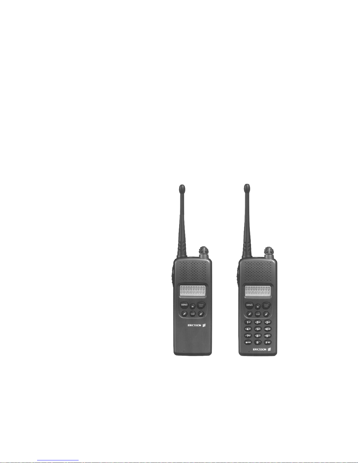
Model:
IPE-100 (NON-DTMF) KRD 103 124/1
IPE-200 (DTMF) KRD 103 124/2
Dimensions (H x W x D): 5.1” x 2.1” x 1.7” (130 x 52 x 42 mm)
Weight: 12 oz (with High capacity battery)
Battery Life:
Extra high capacity battery 16 Hrs.
High capacity battery 10 Hrs.
Maximum Capacity:
EDACS Systems/Groups 64
Operating Voltage: 6.5 V (Nominal)
Operating Temperature Range: -22°F to + 140°F (-30°C to +60°C)
ENVIRONMENTAL
STANDARD U.S. MIL-STD 810E
Methods/Procedures *
Low Pressure 500.3/1,2
High Temperature 501.3/1,2
Low Temperature 502.3/1,2
Temperatue Shock 503.3/1
Solar Radiation 505.3/2
Blowing Rain 506.3/1
Humidity 507.3/2 (Cycle 5)
Salt Fog 509.3/1
Blowing Dust 510.3/1
Vibration 514.4/1 CAT 1, 10
Shock 516.4/1,4
* Also meets equivalent MIL-STD 810 C&D
TRANSMITTER (25 kHz Channel)
Frequency Range (MHz): 806-825
Rated Output Power (Watts): 1.0
RF Output Impedance (Ohms): 50
Frequency Stability (ppm): 1.5%
Conducted and Radiated Spurious (dBc): Per TIA
FM Hum and Noise (dB): -39
Audio Response (per EIA 603): max 3%
4

RECEIVER (25 kHz Channel)
Frequency Range (MHz): 851-870
RF Input Impedance (Ohms): 50
Sensitivity (uV per EIA 603 12 dB SINAD): -118 dBm
Selectivity (dB per EIA 603): -60
Frequency Stability (ppm): 1.5%
Intermodulation Rejection (dB): -66
Spurious Rejection (dB): -65
FM Hum and Noise (dB): -41
Audio Response (per EIA 603): <3%
Audio Output (Watts): 0.5
AE/LZB 119 1890 R1A
5

A
E/LZB 119 1890 R1A
DESCRIPTION
The IPE Series radio is a synthesized, microprocessorbased, high performance portable FM radio designed for
EDACS systems. The lightweight radio provides reliable
communications operation in Enhanced Digital Access
Communications System (EDACS) trunking environments.
Dispatch features such as group calls, individual calls,
agency/fleet calls, etc. are offered. Duplex interconnect is
also provided in EDACS trunked environments while
operating in the Telephone Interconnect Mode.
The radio is manufactured with advanced state-of-theart technology and designed with a minimum of serviceable
parts. It is not practical to service the radio to component
level (in the field). Technicians servicing this radio sho uld
only be concerned with isolating a problem to software or
hardware. Repair is limited to reloading software or
replacing the circuit board. There are no alignments or
adjustments to be made. This manual provides the
instructions for:
• • basic radio operation
• • programming the radio personality and flash code
• • isolating a problem to hardware or software
• • disassembling the radio and replacing the circuit
board
RELATED MANUALS
Operator's Manual.....................................AE/LZT 123 1907
EDACS-2 PC Programming Guide..........................TQ-3373
Portable Handsfree User’s Guide..............AE/LZT 123 1882
USER PROGRAMMABLE FEATURES
•
Store Telephone
Number (name)
•
Recall Telephone
Number (name)
•
EDACS System
•
Group Selection
•
Electronic
Lock/Call
restrictions
•
Battery Saver
•
Ring Volume
•
Ring Tone
•
LCD contrast
•
Key Burst, Tones,
Clicks
•
Backlight Selector
•
Battery Voltage
•
Personality
Programming
•
Resettable
Accumulated Call
Time
•
Last Call Time
Stores telephone numbers (names) in
memory.
Recalls telephone numbers (names)
from memory.
Change current EDACS System.
Change current EDACS Group.
Locks the radio to restrict
unauthorized use and accepts
personal lock code.
Selects amount of battery savings.
Changes ring volume and type.
Selects the ring tone frequency.
Sets LCD display contrast.
Selects whether keypad numeric keys
(0-9, #, *) produce DTMF tones or
key clicks.
Keypad or display illumination to be
automatic or switched off.
Shows the input battery voltage to the
radio, for example, 6-3 = 6.3 volts.
Indicates the radio is in the PC
Programming mode.
Used to display total air time since
last reset.
Shows minutes and seconds of last
call made.
PC PROGRAMMABLE FEATURES
RADIO FEATURES
The lightweight (12 oz) radio provides cellular-like
duplex interconnect with the power and efficiency of
EDACS trunking. The radio takes advantage of EDACS
Infinity battery technology and provides up to 16 hours of
standby on a single charge. The IPE offers all the duplex
interconnect features in a cellular telephone including:
• full duplex interconnect
• familiar telephone - style keypad
• 25-number call list
• last number redial for fast, effortless use
• call length timer
• two-line, 10-character alphanumeric display that's
backlit for nighttime use
6
The radio is PC Programmable, which allows the radio
to be customized or upgraded quickly and easily. All PC
programmable functions are controlled by the
microprocessor and are field programmable using the
EDACS-2 PC Programmer and a compatible DOS based
PC. The programmable parameters are stored in a EPROM
and accessed by the microprocessor as needed. Refer to the
EDACS-2 PC Programming manual for detailed
programming instructions.
CIRCUIT DESCRIPTION
The block diagram for the IPE-200 is shown in Figure
1.
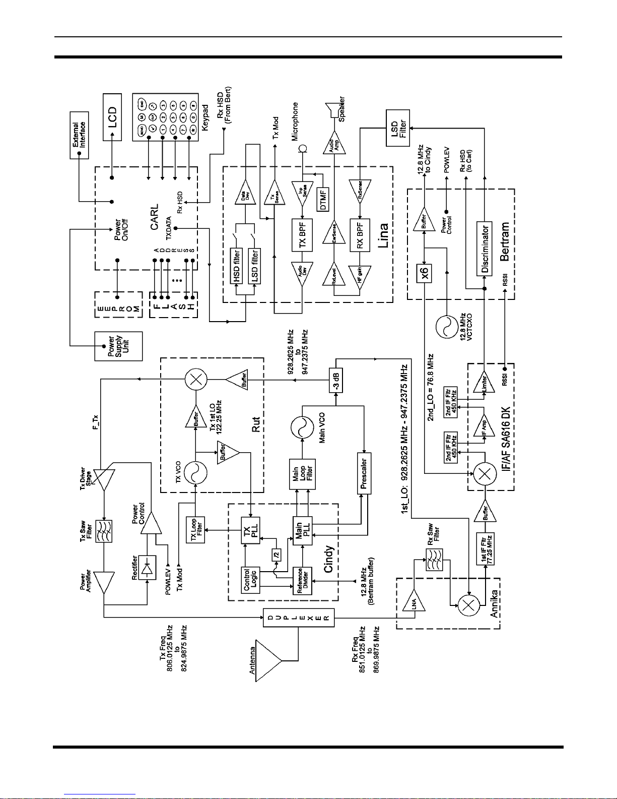
AE/LZB 119 1890 R1A
Figure 1 - Block Diagram
7
 Loading...