

Page 1

LBI-39190
Installation and Maintenance
EDACS
Data Advantage
E
Page 2

LBI-39190
TABLE OF CONTENTS
TABLE OF CONTENTS...........................................................................................................................................................2
PREFACE...................................................................................................................................................................................4
OVERVIEW...............................................................................................................................................................................5
VME CHASSIS......................................................................................................................................................................6
RF CONTROL STATIONS...................................................................................................................................................6
RF CONTROL STATION POWER SUPPLY ......................................................................................................................6
NETWORK PLANNING..........................................................................................................................................................7
ADDRESS TYPES ................................................................................................................................................................7
IP Addresses.....................................................................................................................................................................7
EDACS Addresses ............................................................................................................................................................8
Ethernet Addresses...........................................................................................................................................................8
IP HOST CONFIGURATIONS.............................................................................................................................................9
Assigning Network IP Addresses......................................................................................................................................9
Assigning Individual IP Addresses.................................................................................................................................11
Assigning LIDs to IP Hosts ............................................................................................................................................11
Sample SYSTEM.TXT File with Network Layer RDTs ...................................................................................................12
Sample SYSTEM.TXT File with Non-Network Layer RDTs ...........................................................................................13
Sample SYSTEM.TXT File with Eight Port Data Advantage .........................................................................................14
Sample SYSTEM.TXT File with commands under [system] heading.............................................................................15
INSTALLATION.....................................................................................................................................................................16
DATA ADVANTAGE CONTENTS...................................................................................................................................16
INSTALLATION ORDER ..................................................................................................................................................17
MVME147 BOARD SETUP...............................................................................................................................................18
VCOM24 BOARD SETUP..................................................................................................................................................19
CONNECTING IP HOST COMPUTERS...........................................................................................................................21
MODIFYING THE CONFIGURATION OF HOSTS.........................................................................................................21
TIGHTENING THE DATA ADVANTAGE'S PASSWORD SECURITY (OPTIONAL) .................................................21
CONNECTING THE DIAGNOSTIC TERMINAL ............................................................................................................21
CONNECTING THE PRINTER (OPTIONAL)..................................................................................................................22
CONNECTING WNI SERIAL PORTS TO THE RF CONTROL STATIONS..................................................................22
CONNECTING RF CONTROL STATIONS TO THE POWER SUPPLY ........................................................................23
CUSTOMIZING THE DATA ADVANTAGE CONFIGURATION..................................................................................23
CONNECTING TO AN AC SOURCE................................................................................................................................24
TURNING ON THE DATA ADVANTAGE EQUIPMENT AND LOADING THE SOFTWARE AND
CONFIGURATION.............................................................................................................................................................24
PROGRAMMING ...............................................................................................................................................................24
REQUIRED EQUIPMENT.............................................................................................................................................25
PROGRAMMING STEPS...............................................................................................................................................25
MAINTENANCE.....................................................................................................................................................................31
MODIFYING PASSWORDS..............................................................................................................................................31
HARD DISK CLEANUP.....................................................................................................................................................31
LOADING NEW SOFTWARE RELEASES.......................................................................................................................31
DATA ADVANTAGE BOOT SEQUENCE .......................................................................................................................32
VCOM24 BOOT ERROR CODES......................................................................................................................................33
TROUBLESHOOTING GUIDE..........................................................................................................................................34
Troubleshooting tools.....................................................................................................................................................34
Copyright December 1996, Ericsson Inc.
2
Page 3

LBI-39190
RF Control Station Statistics.......................................................................................................................................... 36
System Startup................................................................................................................................................................37
Network Connections .....................................................................................................................................................39
RF Control Stations........................................................................................................................................................40
Radios / RDTs ................................................................................................................................................................41
Excessive Error Rate......................................................................................................................................................42
ICMP MESSAGES RETURNED BY DATA ADVANTAGE............................................................................................43
FORCING A HARD DISK REFORMAT...........................................................................................................................43
FUSES .................................................................................................................................................................................44
CAP Board Fuse ............................................................................................................................................................44
SCSI Fuse.......................................................................................................................................................................44
VCOM24 Fuses.............................................................................................................................................................. 45
PIN OUT FOR THE DIAGNOSTIC TERMINAL CABLE................................................................................................46
PIN OUT FOR DATA INTERFACE CABLE ....................................................................................................................46
PIN OUT FOR RADIO SHELF HARNESS / DATA INTERFACE...................................................................................46
PIN OUT FOR THE PROGRAMMING CABLE...............................................................................................................47
PIN OUT FOR RADIO SHELF HARNESS / RADIO PROGRAMMING.........................................................................47
3
Page 4

LBI-39190
PREFACE
This is one of four manuals for Data Advantage. It contains instructions for installing and maintaining the Data
Advantage equipment. Network planning and the boot sequence are also documented in this manual. Other
relevant documents are:
Data Advantage Technical Description (LBI-39188):
This manual contains a detailed description of the Data Advantage capabilities, interfaces, and hardware.
Data Advantage User's Reference Manual (LBI-39191):
This manual contains information for using the Data Advantage command shell. This command shell
services the Diagnostic Terminal and Telnet logins.
Data Advantage Configuration Reference Manual (LBI-39189):
This manual contains the information required to configure the Data Advantage.
Internetworking with TCP/IP, Volume I, by Douglas E. Comer:
This is an excellent (but unofficial) source of information about Internet Protocol.
EDACS CommServ Programmers Guide (LBI-38835):
This manual documents the CommServ product. CommServ provides an application program interface
that simplifies Radio Data Terminal (
use with MS-DOS (trademark of Microsoft Corporation) and PC-DOS.
) programming by providing an RDI Data Link Layer. It is for
RDT
Mobile Data Terminal Interface, Hardware and Protocol, Version 1.92
This manual documents the RDI Interface.
If you are unable to resolve a problem or need additional technical assistance, contact Ericsson’s Technical
Assistance Center (TAC) at the number shown on the last page of this manual.
4
Page 5
LBI-39190
OVERVIEW
Ericsson’s EDACS Data Advantage is a data gateway that provides services for data communication between
the Radio Data Terminals (RDTs) on a EDACS trunked radio network and computer hosts on a wired network.
Data Advantage provides an Ethernet host interface using Internet Protocol (IP), and supports EDACS Network
Header in the data messages to and from a Radio Data Terminal (RDT) so that the applications on both the hosts
and the RDTs can use off-the-shelf software and hardware.
Data Advantage connects to the EDACS Network through multiple serial ports operating at 19,200 bps.
Depending on the configuration, Data Advantage can contain four or eight ports. Each port is connected to an
EDACS mobile radio with built-in Radio Data capability. Each radio connected to a Data Advantage port is
programmed as “Data Host” and “Data Only” radio. All data calls are between a Data Host radio and a Terminal
radio connected to an RDT.
By using RF data and standard IP protocol, Data Advantage provides an Open System solution for wireless data
on a single site EDACS system.
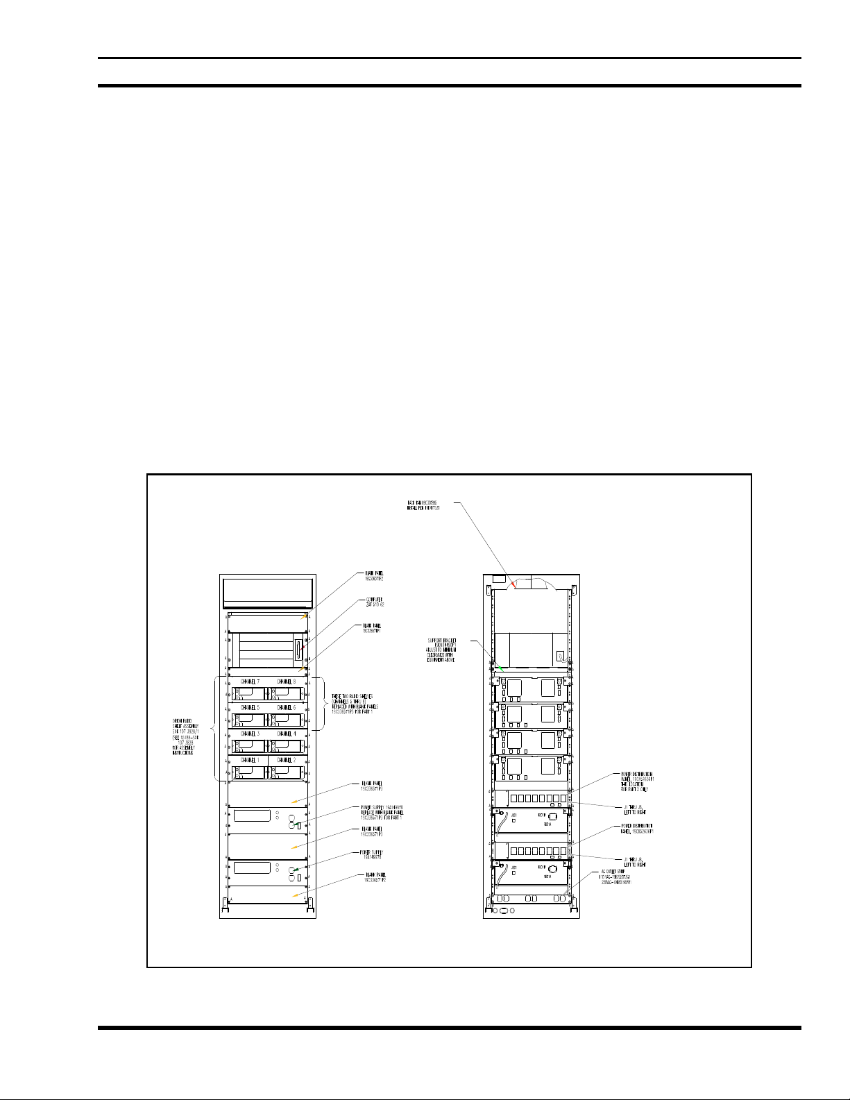
Data Advantage consists of several subassemblies housed in a standard 19” wide x 69” tall cabinet. These
include the RF control station shelves, the 4U VME Chassis with microprocessor boards and IO modules, and a
power system for supplying DC power to the radios. Data Advantage can be configured to have four or eight RF
control stations.
Front View Back View
Figure 1 - Data Advantage Rack
5
Page 6

LBI-39190
VME CHASSIS
The 4U VME Chassis consists of the following components:
• VME bus backplane
• MVME147 microprocessor board
• One or two VCOM24 microprocessor board(s) depending on configuration.
• 3.5” hard disk drive
• 3.5” floppy disk drive
The MVME147 board and VCOM24 board(s) are connected to IO modules at the back of chassis which have
connection points for console terminal, a printer, the Ethernet LAN and RF control stations. The microprocessor
boards and IO modules are mounted horizontally in the chassis. Each VCOM24 board has four DB25 type
female connectors providing four RS-232 serial communication channels. Each channel is connected to a single
RF control station in a radio shelf.
The VME chassis has an internal power supply system. The AC input circuitry of the power supply is auto
ranging, capable of using 90 - 132 VAC at 47 - 65 Hz or 180 - 264 VAC at 47 - 65 Hz. The power supply has
remote sense lines for all three DC outputs (+5V, +12V, -12V), and includes an AC “POWER ON” solid state
LED indicator.
RF CONTROL STATIONS
An RF control station is an EDACS mobile radio with a built-in Radio Data Interface (RDI). Data Advantage
uses RF control stations to transmit and receive data calls on an EDACS RF channel. Each RF control station is
housed in a shelf, and each shelf contains two RF control stations.
There are two or four RF control station shelves which are rack mountable shelf assemblies. The control heads of
radios are visible from the front of the shelf when the cabinet door is open. Also, the front of the shelf has a DB9
connector and a two position switch for programming purposes. The rear of the shelf has a power connector, an
8-pin modular connector and an antenna connector for each radio in that shelf.
RF CONTROL STATION POWER SUPPLY
One or two external power supplies power the RF control stations in Data Advantage. The power system
performs AC/DC conversion. The output of each power supply is connected to a power distribution panel which
provides up to seven 13.6 VDC outputs to RF control stations (only four are used).
6
Page 7

LBI-39190
NETWORK PLANNING
Prior to configuring and installing the Data Advantage equipment, it is important to determine the addresses that
will be used. In addition to this document, the Data Advantage Technical Description Manual (see Preface)
explains the concepts behind the Data Advantage.
ADDRESS TYPES
There are three main types of addresses used when configuring the Data Advantage equipment: IP Addresses,
EDACS Addresses and Ethernet Addresses. This section provides basic information on the address types.
IP
Addresses
IP Addresses are made up of four octets separated by periods. The addresses are typically written in decimal, but
can be hexadecimal. 1.0.0.2 is an example of an IP Address. Each octet can range from decimal 0 to 255 or hex
0x00 to 0xff.
IP Addresses contain a
address is based on the
octet.
CLASS First Octet Network ID Portion Host ID Portion Number of Host IDs
A 1-126 First octet Last three octets 16M
B 128-191 First two octets Last two octets 65K
C 192-223 First three octets Last octet 254
D 224-239 N/A N/A N/A
E 240-255 N/A N/A N/A
Several conventions and special cases should be noted:
1. If the IP Address is all zeros, it refers to this host.
2. If the IP Address is all ones, the destination is all hosts on the local network.
3. If the Network ID is all zeros, the IP Address refers to a host on this network. This is only valid at
system startup and is not a valid destination address.
4. If the Host ID is all zeros, the IP Address refers to the Network ID.
5. If the Host ID is all ones, the IP Address refers to all hosts on the specified network (not valid on the
EDACS Network).
Network ID
Class
portion and a
of the address. The Class of the address is determined by the value of the first
Host ID
portion. The number of octets in each portion of the
6. If the first octet is 127, then this is a local loop-back.
7. Class D addresses are multicast.
8. Class E addresses are reserved.
7
Page 8

LBI-39190
EDACS Addresses
There are two types of EDACS Addresses, Logical IDs (LIDs), and Group IDs (GIDs). LIDs are used to
reference a single radio. GIDs are used to reference a group of radios. LIDs and GIDs are programmed into
radios and can be changed as desired.
TYPE Range
LID 1 - 16,382
GID 1 - 2047
In Data Advantage, there are two categories of radios: Data Host Radio and RDT radio. A Data Host Radio is
fixed RF equipment housed in the Data Advantage cabinet called RF control station. An RDT radio is connected
to a Radio Data Terminal which is mobile RF equipment. A Data Host Radio must be assigned a LID in the range
1-63. The LID assigned to an RDT should be in the range 64-16382. It is not recommended to assign a LID in the
range 1-63 to an RDT radio, even though it is allowed in the EDACS.
TYPE Range
LID for Data Host Radio 1 - 63
LID for Terminal Radio 64 - 16,382
Ethernet Addresses
Ethernet Addresses are 48-bit addresses assigned by hardware vendors. Normally, an Ethernet Address is
permanently assigned to a hardware device. The Address Resolution Protocol (ARP) that is built into the
Internet Protocol allows devices to query each other for their Ethernet Address. For these reasons, Ethernet
Addresses are of minor importance when setting up a network, and are not discussed in detail.
8
Page 9
IP HOST CONFIGURATIONS
Assigning Network IP Addresses
LBI-39190
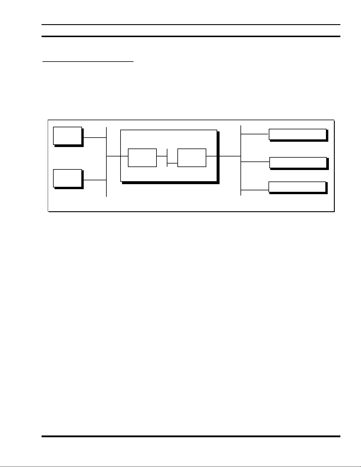
An
internet
unique network address. The first step in setting up an internet is to determine the IP Network Addresses that
will be used. In the simplest case, three network addresses will be used: one each for the IP Host Network, the
Internal Data Advantage Network, and the EDACS Network. A Class A, B, or C address can be used for any of
the addresses. Class D and E addresses can not be used.
internet.
Host A
consists of multiple networks connected together, with each network on the internet assigned a
A Network Address can only be used once in an
Data Advantage
CAP
WNI
Radio/RDI/RDT
Radio/RDI/RDT
Host B
Internal Network
Radio/RDI/RDT
IP Host Network
Figure 2 - An IP host internet with no IP Addresses
If the IP Host Network already exists, its Network Address will have already been assigned. Otherwise it will
need to be assigned. For this example, the IP Host Network is an existing network with an address of 1.0.0.0.
EDACS Network
Next, the Internal Data Advantage Network Address needs to be assigned. Since the number of individual
addresses required on this network is small (one address per board), a Class C address is recommended. Data
Advantage will default its internal Network Address to 192.168.100.0. If this Network Address isn't available,
another one can be used.
Finally, an available Network Address needs to be chosen for the EDACS Network. A Class C address typically
isn't used since each radio must be assigned an address, and even a single site EDACS System can have more
than 254 radios. A Class B address can be used to conserve Class A Network IDs. If an EDACS network ID is
not specified, Data Advantage will default to a value of 172.16.0.0. For this example, it is assumed that you
have chosen to assign Network Address 128.1.0.0 to your EDACS Network.
Remember that since each Network Address must be unique, the addresses selected should be reserved with the
Network Administrator so that they are not used elsewhere on the internet.
9
Page 10
LBI-39190
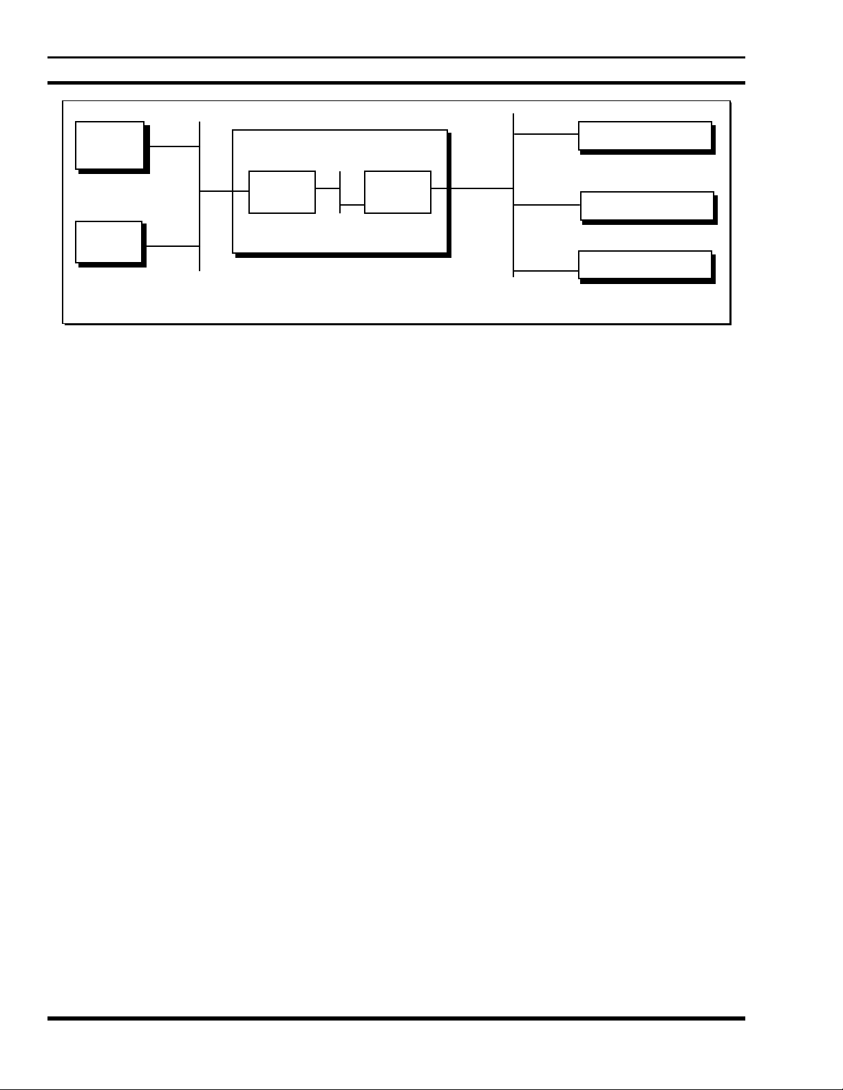
Host A
Host B
CAP
IP Host Network
1.0.0.0
Figure 3 - An IP Host internet with Network Addresses assigned
Radio/RDI/RDT
Data Advantage
WNI
Radio/RDI/RDT
Internal Network
199.0.0.0
Radio/RDI/RDT
EDACS Network
128.1.0.0
10
Page 11
LBI-39190
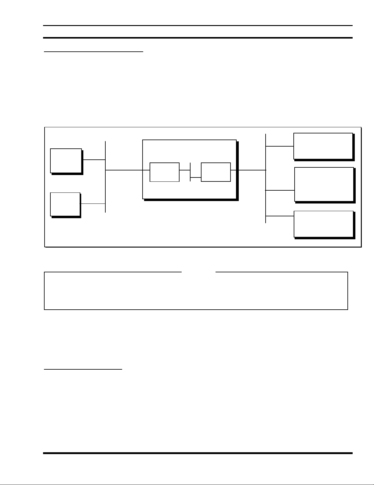
Assigning Individual IP Addresses
After the Network Addresses have been decided upon, individual addresses within each network should be
assigned.
For the purposes of this example, Host A has previously been assigned an address of 1.0.15.12 and Host B has
previously been assigned an address of 1.0.15.13. The CAP’s External Interface must be assigned an individual
address on Network 1.0.0.0. For this example, it is assumed that address 1.0.15.14 has been chosen.
Data Advantage can auto-configure the individual IP addresses for its Internal Network and the EDACS Network.
While the defaults can be overridden by explicitly assigning individual addresses, it is simplest to let Data
Advantage do the work.
Radio/RDI/RDT
Data Advantage
128.1.0.64
Host A
1.0.15.12
1.0.15.14
CAP
WNI
Radio/RDI/RDT
128.1.0.65
Internal Network
Host B
1.0.15.13
199.0.0.0
Radio/RDI/RDT
Host Network
1.0.0.0
Figure 4 - An IP host internet with individual addresses assigned
NOTE
If a radio’s LID is changed, a new unit IP Address will be associated with the radio. If this is not desired, the mapping
can be changed.
EDACS Network
128.1.0.0
In this configuration Data Advantage and the Hosts are on the same network. In a more complex configuration,
there could be multiple gateways between Data Advantage and the Hosts. In this case, additional entries need to
be installed in the Data Advantage routing table to enable communication between the IP hosts and RDTs.
Regardless of the configuration, the CAP’s external IP Address must be a valid address on the network to which
it is connected.
Assigning LIDs to IP Hosts
In Data Advantage there is no need to assign an EDACS address to an IP host. If the EDACS Network Layer is
used, the EDACS Network Layer header includes the IP address of an IP host. If the EDACS Network Layer is
not used, Data Advantage obtains the IP address of the IP host using port-to-IP address mapping in the
configuration file. A None-Network Layer RDT must know which port(s) to send messages to in order to reach a
particular IP Host. Refer to the Data Advantage Technical Description Manual (see Preface) for detailed
information.
128.1.64.1
11
Page 12

LBI-39190
Sample SYSTEM.TXT File with Network Layer RDTs
The following SYSTEM.TXT configuration file matches the example configuration if all RDTs use the network
layer. Since there is no [device_config_table] specified , Data Advantage creates default entries for all LIDs from
64 to 16382. The IP address for the RDT defaults use the network ID of the defined EDACS Network, and the
range of the host IDs is from 0.64 to 63.255. Data Advantage also creates default entries for all GIDs from 1 to
2047, using the same network ID, with the range of the host IDs from 64.0 to 71.255.
###############################################
# SYSTEM.TXT configuration file.
###############################################
[board 1]
type cap
load 01.02/loads/DACAP.SX
[board 2]
type wni
load 01.02/loads/WNI.SX
[ip]
cap_ext_address 1.0.15.14
[edacs_network]
ip_network_id 128.1.0.0
In the above example there is no “port_dir” command specified under the board 2. Data Advantage will default
ports 0 and 1 to be Input ports and ports 2 and 3 to be Output ports. Note that if the [device_config_table] is not
specified, the Data Advantage will default all RDTs to Network Layer RDTs.
12
Page 13

LBI-39190
Sample SYSTEM.TXT File with Non-Network Layer RDTs
In the following SYSTEM.TXT, the same IP addresses are assigned to LIDs 64 - 16382, except that all RDTs are
without Network Layer. In addition, there are four port commands that associate ports 0 and 1 to Host A, and
ports 2 and 3 to Host B. All messages received at port 0 would be forwarded to Host A if the originating RDT
does not have the EDACS Network Layer. The Data Advantage Configuration Reference Manual (See Preface)
contains a detailed explanation of each command.
###############################################
# SYSTEM.TXT configuration file.
###############################################
[board 1]
type cap
load 01.02/loads/DACAP.SX
[board 2]
type wni
load 01.02/loads/WNI.SX
port_dir 0 in
port_dir 1 in
port_dir 2 bi
port_dir 3 bi
[ip]
cap_ext_address 1.0.15.14
[edcas_network]
ip_network_id 128.1.0.0
[device_config_table]
rdt 64 - 16382 128.1.0.64 FALSE
port 0 1.0.15.12
port 1 1.0.15.12
port 2 1.0.15.13
port 3 1.0.15.13
13
Page 14

LBI-39190
Sample SYSTEM.TXT File with Eight Port Data Advantage
In the following SYSTEM.TXT two WNI boards are configured. This configuration supports eight ports. Note
that under the heading [board 2] and [board 3] only the “type” command is specified. Data Advantage will
default the application executable file to “01.02/loads/WNI.SX” and the ports 0 and 1 on each WNI to be input
ports and the ports 2 and 3 on each board to be Output ports, since there are no “load” and “port_dir” command
specified.
###############################################
# SYSTEM.TXT configuration file.
###############################################
[board 1]
type cap
load 01.02/loads/DACAP.SX
[board 2]
type wni
[board 3]
type wni
[ip]
cap_ext_address 1.0.15.14
[edcas_network]
ip_network_id 128.1.0.0
[device_config_table]
rdt 64 - 16382 128.1.0.64 FALSE
port 0 1.0.15.12
port 1 1.0.15.12
port 2 1.0.15.13
port 3 1.0.15.13
14
Page 15

LBI-39190
Sample SYSTEM.TXT File with commands under [system] heading
In the following SYSTEM.TXT there are several commands under the [system] heading. A command under this
heading is used to set up global system parameters. In this example the msg_timeout command has a value 100. A
message can be queued in Data Advantage for as long as 100 seconds before being sent out to the RDT. The
edacs_err_retries command has two parameters. The first parameter specifies the number of retries in case of
error when sending message to a RDT. The second parameter specifies the amount of time (in tenths of a second)
that Data Advantage should wait after receiving an error indication from an RF control station before attempting
a retry.
###############################################
# SYSTEM.TXT configuration file.
###############################################
[board 1]
type cap
load 01.02/loads/DACAP.SX
[board 2]
type wni
[ip]
cap_ext_address 1.0.15.14
[system]
msg_timeout 100
edacs_err_retries 220
[edcas_network]
ip_network_id 128.1.0.0
[device_config_table]
rdt 64 - 16382 128.1.0.64 FALSE
port 0 1.0.15.12
port 1 1.0.15.12
port 2 1.0.15.13
port 3 1.0.15.13
15
Page 16

INSTALLATION
DATA ADVANTAGE CONTENTS
Data Advantage is shipped with the following items:
VME chassis containing multiple microprocessor boards on a VME bus backplane
•
Eight or four (depending on configuration) Orion Mobile Radios used as RF control stations
•
Four or two (depending on configuration) RF control station shelves with internal cabling
•
One or two RF control station power supplies (depending on configuration)
•
One or two power distribution pannels (depending on configuration)
•
69” Data Advantage cabinet
•
VT100 compatible terminal with power cord
•
Terminal interface cable
•
RF control station data interface cables
•
RF control station power cables
•
AC line cord
•
LBI-39190
Antennas for RF control stations
•
AC outlet strip
•
Data Advantage Technical Description manual
•
Data Advantage Installation and Maintenance Manual
•
Data Advantage Configuration Reference Manual
•
Data Advantage User's Reference Manual
•
Data Advantage Loader Diskette on one 3 1/2" floppy
•
Data Advantage Application Diskettes on two 3 1/2" floppies
•
Data Advantage Configuration Diskette on one 3 1/2" floppy
•
The following items are not provided as part of Data Advantage:
IBM compatible printer and cable (optional)
•
DB15 AUI Ethernet Transceiver and cable
•
Network Device Driver Software [i.e. EDACS Network Driver (END)]
•
16
Page 17

LBI-39190
INSTALLATION ORDER
The Data Advantage Software Release Notes Manual (AE/LZT 123 1893) contains the installation procedure.
This section provides the installation steps for the Data Advantage and the Host Computers as part of that
procedure. The steps documented in this section are:
1. Set up MVME147 Board
2. Set up VCOM24 Board
3. Connect the Host Computer(s).
4. Modify the Host Computers Routing.
5. Tightening Data Advantage’s Password Security (Optional).
6. Connect the Diagnostic Terminal to the Data Advantage equipment.
7. Connect the printer to the Data Advantage equipment (optional).
8. Connect the VCOM24 serial ports to the RF control stations.
9. Connect the RF control stations to the power supply.
10.Customize the Data Advantage configuration.
11.Connect the Data Advantage equipment to an AC source.
12.Turn on the Data Advantage equipment and Load the Software.
13.Program the RF control stations.
17
Page 18

LBI-39190
MVME147 BOARD SETUP
WARNING
The Data Advantage equipment must be powered off when removing or inserting processor
boards.
There are two types of processor boards installed in the Data Advantage VME chassis: MVME147 and
VCOM24. There will be only one MVME147 board, located in the bottom slot (slot 1). There will be one or
two VCOM24 boards, beginning at slot 3. Each of these boards requires the installation of an EPROM set and
the correct jumper settings for normal operation.
Shown below are the jumper settings for the MVME147 board. The two EPROMs for this board are to be
installed in U22 and U30. U1 and U15 will not have any EPROMs installed.
F1
J1 J2
Figure 5 - MVME147 Board Jumper Settings, Fuses, and Sockets
J7
J5
J3
U30U22U15U1
J6
Spare Fuse *
J8
J9
* The Spare Fuse is on the 1992 revision of the board, but not the 1988 revision. The revision date is generally
on the back near the VME connectors.
18
Page 19

LBI-39190
VCOM24 BOARD SETUP
Shown below are the jumper settings for the VCOM24 board. The two EPROMs for this board are to be
installed in U49 and U50. U54 and U55 will not have any EPROMs installed.
F1
F2 F3
J10
J2 J3 J4 J5 J6 J7J8 J9
J11
J24
J12J13
J25 J26 J27
U49
U54
J15 J16
J21* J22 J23*
J14
J17
U50
U55
J18
J19
J20
Figure 6 - VCOM24 Board Jumper Settings, Fuses, and Sockets
* Jumpers J21 and J23 are for sockets U54 and U55. Any settings should work. Suggested settings are shown
above.
19
Page 20

LBI-39190
Each VCOM24 board supports four serial data communication ports. Signals for all four ports are brought to P2
at TTL levels and require off-board translation to the proper signal levels as required by the selected
communication standard. For Data Advantage, the Serial Communication Interface (SCI) module board allows
each VCOM24 port to be configured for EIA-232-C communication standard. The SCI-232 module boards are
not directly connected to the VCOM24 board, but through a small connector board for adapting SCI boards to the
VCOM24.
When communicating with an RF control station, a serial port on the VCOM24 board functions as a DTE port.
The DTE/DCE option is jumper-selectable. Set the jumpers on all four SCI-232 boards for each VCOM24 board
as shown below to configure the VCOM24 board’s serial ports as DTE ports.
J5
A
B
1
A
B
1
2
J4
2
Figure 7 - Jumping SCI-232 for DTE
3
3
A
B
A
B
J6
1
1
2
J7
2
3
3
20
Page 21

LBI-39190
CONNECTING IP HOST COMPUTERS
1. Connect your Ethernet Transceiver to the Data Advantage using the DB15 AUI Ethernet port on the rear of
the Data AdvantageVME Chassis.
2. Connect your Ethernet Cable to your Ethernet Transceiver.
MODIFYING THE CONFIGURATION OF HOSTS
For most computers, a routing entry must be added to instruct the host computer to use Data Advantage as the
next gateway for the IP Network ID assigned to the EDACS Network. Symbolic names can also be defined as
desired for the Data Advantage CAP External Address, radios, and groups. These changes will normally be made
by the System Administrator of the host computer(s). The following example commands will work on most
UNIX (trademark of UNIX System Laboratories, Inc.) systems. Refer to the host computer's documentation for
the actual commands.
Assuming that the CAP External Address had been assigned to 1.0.15.14, the following statement could be added
to the /etc/hosts file to assign a symbolic name to Data Advantage Ethernet Network Interface.
1.0.15.14 da_gateway
Assuming that the EDACS IP Network ID had been assigned to 128.1.0.0, the following statement could be
added to the /etc/rc.local file to route all messages destined to radios or groups through Data Advantage.
route add net 128.1.0.0 da_gateway 5
If the customer network contains routers between the Hosts and Data Advantage, the routers and the Hosts will
need updated routing information. Normally, the administrators of the customer’s network are involved in
planning the network and making the routing changes.
TIGHTENING THE DATA ADVANTAGE'S PASSWORD SECURITY (OPTIONAL)
Data Advantage comes with three user id's installed; "root", "user", and "guest". The passwords for these user
id's are the same as the user IDs. All of the user ids and passwords are in lower case. The passwords can be
changed using the "passwd" command. See the Data Advantage User's Reference Manual for more information.
CONNECTING THE DIAGNOSTIC TERMINAL
A VT100 compatible terminal with a power cord and a terminal interface cable is included with the Data
Advantage equipment. To connect the terminal to the Data Advantage VME Chassis, perform the following:
1. Attach the female connector of the terminal interface cable to the Modem connector on the terminal
(refer to the terminal user's manual for location).
2. Attach the male connector of the terminal interface cable to the SERIAL PORT 1/CONSOLE connector
on the rear of the Data Advantage VME Chassis.
3. Turn on the power to the terminal per the instructions in the terminal’s manual.
4. Verify that the terminal is in VT100 emulation mode via the setup screen. Change and save the setup if it
isn't.
5. Set the tabs to a tab every eight columns via the setup screen.
21
Page 22

LBI-39190
CONNECTING THE PRINTER (OPTIONAL)
NOTE
A printer and printer cable are NOT included with the Data Advantage equipment.
1. Connect the female end of the printer cable to your printer.
2. Connect the male end of the cable to the PRINTER connector on the rear of the Data Advantage VME
Chassis.
3. Turn on the printer.
CONNECTING WNI SERIAL PORTS TO THE RF CONTROL STATIONS
Each of the four serial ports on the rear panel of a VCOM24 board connects into an 8-pin connector on the rear
of the RF control station shelf. Within the shelf, this connector is wired to the radio. The following figure shows
the interconnections between the RF Control Stations and the VCOM24 board’s serial ports. Note the numbering
of the RF Control Stations and the serial ports, and connect each RF Control Station to the serial port with the
same number. It is important to follow this mapping between a RF Control Station and a serial port on a
particular VCOM24 board to simplify the monitoring and trouble shooting of the system.
1. Connect the DB25 connector of a data interface cable to a serial port of the VCOM24 board.
2. Connect the 8-pin connector on the other end of the data interface cable to either connector J3 or J5 on the
rear of the RF control station shelf.
VCOM24 Board 2
VCOM24 Board 1
RF Control Station Shelf
RF Control Station Shelf
RF Control Station Shelf
RF Control Station Shelf
Figure 8 - Interconnection between RF Control Stations and VCOM24 Serial Ports
56 7
123
4
3
2
R4
R7R8
R5R6
R3
1
8
4
R1R2
22
Page 23

LBI-39190
CONNECTING RF CONTROL STATIONS TO THE POWER SUPPLY
A separate power system is provided for the RF control stations that consists of one or two power supplies
depending on the configuration. Each power supply (PS) is connected to a DC power distribution panel (PDP).
The power supply is a rack mountable assembly each supplying four RF control stations. The DC output of the
power supply is connected to a power distribution panel that provides up to seven +13.6 VDC outputs to RF
control stations (only four connectors are used). On the RF control station side, the rear of the shelf has two
power connectors, one for each radio.
Use the following instructions to connect the RF control stations to the power supply. Note that a power
connector on the shelf should be connected to a connector on the power distribution panel with the same number
to minimize the cable length.
1. Connect the connector of the PS-PDP power cable marked “PS” to the output of the power supply. Connect
the connector of the power cable marked “PDP” to a connector in the power distribution panel (preferably the
fifth connector).
2. Locate the power connector of the first RF control station which is on the rear of the first shelf .
3. Locate the first DC output of the power distribution panel (preferably connector 2 on the power distribution
panel).
4. Attach the PDP-RF Control Station power cable to the power connector of the first RF control station.
5. Attach the other end of the power cable to the DC output of the power distribution panel located in step 3.
6. Repeat the step 2 through 5 for other three RF control stations.
7. If it is a eight-port Data Advantage, repeat the steps 1 - 6 for the second group of RF control stations.
RF Control Station
Shelves 1 - 2
4
2
3
1
Power Distribution
Panel (PDP)
Power Supply
Figure 9 - Power Cabling of RF Control Stations
(PS)
13
2
4
CUSTOMIZING THE DATA ADVANTAGE CONFIGURATION
NOTE
Diskettes must be Double Sided High Density (1.44MB).
23
Page 24

LBI-39190
1. Copy the files on the Configuration diskette to a working diskette using a MS-DOS PC.
2. Edit the SYSTEM.TXT configuration file to customize it using information gathered during network
planning.
Security can be increased by setting the maximum number of Telnet and FTP sessions to 0. This disables
Telnet and FTP sessions into the Data Advantage equipment.
3. Verify your configuration when done by entering "syscheck" at the DOS prompt, while on the working
diskette.
Refer to the Data Advantage Configuration Reference Manual for more information.
CONNECTING TO AN AC SOURCE
The AC power strip is mounted in the bottom of the Data Advantage cabinet. The AC line cord goes out from the
cabinet through a hole in the bottom rear of the cabinet . It must be connected to a 120 V, 60 Hz source.
1. Make sure that the power switches on the VME chassis and the RF Control Station power supplies are
in the OFF position.
2. Plug the AC power cable for the cabinet fan into one outlet on the AC power strip.
3. Plug the AC power cable for each RF Control Station power supply into an outlet on the AC power strip.
4. Plug the AC power cable for the VME chassis into one outlet on the AC power strip.
5. Plug the AC line cord for the cabinet into the 120 V, 60 Hz source.
TURNING ON THE DATA ADVANTAGE EQUIPMENT AND LOADING THE SOFTWARE
AND CONFIGURATION
To turn on the Data Advantage equipment and load the software and configuration perform the following steps:
1. If the software has not been loaded previously, insert the Loader diskette into the floppy drive. If the
software has been previously loaded but the configuration hasn’t, insert your configuration working
diskette.
2. Turn on the power of the VME computer using the power switch on the rear of the VME chassis. If the
power switch for the VME computer is already on, reset Data Advantage by pressing the RESET button
on the front of the CAP board.
3. If Data Advantage is turned on (or reset) with a diskette inserted, it will prompt for a new diskette after it
loads the current one. Each time Data Advantage prompts for a diskette, insert an Application diskette or
Configuration Working diskette. When all disks have been loaded, press return with no diskette inserted.
PROGRAMMING
The Orion radios used in Data Advantage are enabled for Mobile Data in the factory. To verify that an Orion
radio is Mobile Data enabled, turn on the radio by rotating the On-Off Volume knob clockwise. If “DATA ON”
is displayed on the control head, the radio is Data enabled.
The parameters in the Orion radio personality need to be customized for the specific EDACS system where it is
to be used. Before starting the programming of the radio, ensure that the equipment required for programming is
available.
24
Page 25

LBI-39190
REQUIRED EQUIPMENT
The following radio programming equipment is required to modify the Personality of an RF Control Station:
• PC (IBM PC/XT/AT or any true compatible with MS-DOS version 3.0 or later with an available serial
port and 640K Internal RAM) - Used to run the EDACS 3 Radio Programming Software.
• EDACS 3 Radio Programming Software (part # TQ3374, version 14 or later) - Used to program an RF
Control Station.
• RS-232 Data Cable (part # 19B235027P1) - Connects the DB-25 male serial port of the PC to the Data
Interface Module. If the PC uses a DB-9 male connector for the serial port, an adapter will be required.
• Data Interface Module (part # 19D438367G2) - Used to adjust logic levels between the Orion radio and
the PC.
• 12 VDC Power Supply (part # 19B800850P2 for 120V, 60 Hz operation, or part # 19B800888P1 for
230V, 50 Hz operation) - Supplies power to the Data Interface Module.
• Programming Cable (part # 19B804722P1) - Connects the Data Interface Module to the Radio Shelf
PROGRAMMING STEPS
The procedure given here describes creating a new Personality, saving the Personality in a file on the PC, and
writing the Personality into the Orion radio with the Radio Programming Software.
1. Load Programming Software:
• Turn on the PC and wait for it to complete its initialization.
• When the C:\>_ or D:\>_ command prompt is shown on the PC monitor, insert the EDACS 3 Radios
Program Disk #1 (Version 14 or later) into the PC’s A (or B) drive, type “A:” (or “B:”), press the Enter
key, type “INSTALL”, and press the Enter key again.
• The Radio Programming Software Installation Procedure screen will appear. In the highlighted
Target Drive field, type in the letter of the PC’s hard disk (usually C or D) and press the F1 (Begin)
function key.
• The PC will read the Program Disk, create a GE directory in the root directory of the hard disk, and load
the programming files into this GE directory. The PC will prompt you to insert Program Disk #2 and #3
when needed. Remove the previous Program Disk, insert the next Program Disk, and press the F1
(Begin) function key to continue the installation. The PC will prompt you when the installation is
complete. Press the Enter key and remove the last Program Disk. If your PC’s hard disk is the C drive,
type “C:” and press the Enter key. The C:\GE\ EDACS\B IN>_ command prompt should now be shown
on the PC monitor. Type in “CD\” and press the Enter key to return to the C:\>_ or D:\>_ c ommand
prompt.
• Copy the D192.SC file from Disk 4 of the Data Advantage Software Kit labeled “System Configuration
Files” to the C:\GE\EDACS3\MRK directory . Without the D192.SC file in the right directory, you can
not program the RF Control Stations correctly.
25
Page 26

LBI-39190
2. Connect Programming Equipment:
• Connect the radio programming equipment to J1/J2 on the Orion Radio Shelf as shown below.
• Move the switch for the Orion radio to be programmed to the up or “PROGRAM” position.
3. Run Programming Software:
• With the DOS command prompt C:\ or D:\ displayed on the PC monitor, type “CD \GE” and press the
Enter key (to go to the directory named GE where the programming files are located).
• Enter “MRK /sc D192” to run the programming software for the RF Control Stations. You will know
that the programming file is running when you see the introductory copyright screen briefly, followed by
the Current Personality screen on the PC monitor. Note: The baud rate on the RDI data link between a
RF Control Station and a system serial port is 19,200 bps. Without the “/sc D192” option you can not
program this baud rate into the Orion radio.
Switch Up To Program
PROGRAM PROGRAM
NORMAL
NORMALJ1 J2
19B904722P1
Programming Cable
with RS-232 Interface
19D438367G2
Data Interface Module
19B800850P2
(115V, 60 Hz)
or
19B800888P1
(230V, 50 Hz)
19B235027P1
RS-232 Cable
EDACS 3 Radios
Program Disks #1 & #2
Version 14 or later
(5 1/4 or 3 1/2 format)
IBM-Compatable
Personal Computer
Serial PortPower Supply:
Figure 10 - Programming Setup
4. Evoke Programming Mode:
• Turn the Orion radio off for one second and then back on again, using the upper left knob on the control
head or by temporarily disconnecting the DC power cable on the back of the shelf. (Ignore any DSP
ERR message that may briefly be displayed when the radio is turned on.)
• Make sure that PC PROG is displayed on the Orion radio. If not, check to make sure that the
programming equipment is connected as shown in the above figure, and that the switch on the front of the
radio shelf is in the up (programming) position. Then, start this step over.
26
Page 27

LBI-39190
5. Create new Radio Personality:
• Using the Current Personality screen as the starting point, press the F4 (New) function key to bring up
the Radio Personality Screen.
• In the Sys Name field, type in a name for the EDACS system. (PLANT1 is used in this manual).
• Press the F8 (More) function key and then F3 (Freq). Press F3 (NewTrk) again to program the
frequencies of the EDACS site used with Data Advantage. Enter all the TX frequencies used by the
EDACS site (RX frequency will be automatically selected once TX frequency is entered).
• Press F10 (Back) to exit the screen for frequency setting. Enter a filename to store the frequency set
entered above (P1_FREQ is used in this manual). Press F1 (Yes) to save the frequency set in the disk file
and go back to the Trunked Frequency Set screen. Press F10 (Back) to go back to the Radio
Personality screen.
• Move the cursor under the Freq Set filed and type in the name of the frequency set entered in the
previous step. This will link the current Radio Personality to the frequency set.
• Press F8 (More) several times until you see the menu item Group. Press F4 (Group), and then F4 (New)
to enter the Group Set defined for the EDACS system. At least one group set must be defined to satisfy
the requirements to define the personality for the Orion radio. Enter the Group name and Group ID for all
the groups (at least one) defined for the EDACS system. Press F10 (Back), and F1 (Yes) to save the
Group set in the disk file. Press F10 (Back) again to go back to the Radio Personality screen.
• Move the cursor under the Group Set filed and type in the name of the Group set entered in the previous
step. This will link the current Radio Personality to the group set.
• In the Radio Personality screen, press F7 (Option) to enter the Radio Option screen. Press F1 (Agency)
to enter the Agency definition. Enter the number of agencies and number of fleets per agency as defined
in the current EDACS system. Press F10 (Back) to go back to the Radio Options screen.
• In the Radio Options screen, press F3 (Data) to enter the Data options. Set the data options as shown in
Figure 14 Radio Data Option screen. Note that when you create the new personality the baud rate
displayed in the Radio Data Options screen is 9600 bps. This is the default value for the baud rate.
Ignore this field. Make sure that you have evoked the programming software with a special option
parameter “/sc D192”. This option parameter will cause the programming software to overwrite whatever
baud rate is in the Personality file with 19200 bps when it is writing the personality to the radio.
• Move the cursor to the Site field. Then type in the site ID of the EDACS system.
• Move the cursor to the Unit field. Then type a LID in the range from 1 to 63 that is not currently in use
in the system. The LID is also called the Host ID of Data Advantage since an Orion radio in Data
Advantage is a Host Radio versus a Terminal Radio which must have a LID larger than 63.
• In the Radio Personality screen, press F2 (Switch) several times until you see the Pwr Lev Field in the
Radio Personality screen. Move the cursor to the Pwr Lev field, and enter 8 to set the power level of
the Transmitter to 8 Watts. This setting generates a 6-Watt power output at the N connector to the
antenna on the rear of the radio shelf.
27
Page 28

LBI-39190
Write Personality to Radio
• Press the F5 (Program) function key to program the Orion radio with the modified personality.
• When programming is complete, press the F10 (Back) function key to go back to the DOS command
prompt. Enter a filename to store the radio personality in a file. Make sure you see the DOS command
prompt displayed on the PC monitor before proceeding.
Disconnect Programming Equipment
• Move the switch on the front of the Orion Radio Shelf to the down or “NORMAL” position.
•
Disconnect the programming equipment from the Orion Radio Shelf.
28
Page 29

LBI-39190
ЪДEricsson Inc.ДДДДДДДДДДДДДДДДДДДДДДДДДДДДДДДДДДДДДДДДДДДДДДДДДДДДДДДДДДДДДДДД¿
³ЪДДДДДДДДДДДДДДДДДДДДДДДДДДДДДДДДДДДДДДДДДДДДДДДДДДДДДДДДДДДДДДДДДДДДДДДДДДДД¿³
³³ Edit EDACS RADIO PROGRAMMER - 3 (14.0) TQ-3374 ³³
³АДДДДДДДДДДДДДДДДДДДДДДДДДДДДДДДДДДДДДДДДДДДДДДДДДДДДДДДДДДДДДДДДДДДДДДДДДДДДЩ³
АДДДДДДДДДДДДДДДДДДДДДДДДДДДДДДДДДДДДДДДДДДДДДДДДДДДДДДДДДДДДДДДДДДДДДДДДДДДДДДЩ
ЙНННННННННННННННННННННННННННННННННННННННННННННННННННННННННННННННННННННННННННННН»
º Radio Personality º
º º
º º
º Sys Name Freq Set Type Site Unit Grp Set Phn Set Ind Set FS Chan º
º 1 PLANT1 P1_FREQ T 4 55 TRUCK º
º 2 º
º 3 º
º 4 º
º 5 º
º 6 º
º 7 º
º 8 º
º º
º º
º Enter System Display Name º
ИНННННННННННННННННННННННННННННННННННННННННННННННННННННННННННННННННННННННННННННН¼
FI F2 F3 F4 F5 F6 F7 F8 F9 F10
Detail Switch Insert Remove Progrm Option More Help Back
Press F9 for field help, Shift F9 for window help
Figure 11 - Radio Personality Screen
ЪДEricsson Inc.ДДДДДДДДДДДДДДДДДДДДДДДДДДДДДДДДДДДДДДДДДДДДДДДДДДДДДДДДДДДДДДДД¿
³ЪДДДДДДДДДДДДДДДДДДДДДДДДДДДДДДДДДДДДДДДДДДДДДДДДДДДДДДДДДДДДДДДДДДДДДДДДДДДД¿³
³³ Frequency EDACS RADIO PROGRAMMER - 3 (14.0) TQ-3374 ³³
³АДДДДДДДДДДДДДДДДДДДДДДДДДДДДДДДДДДДДДДДДДДДДДДДДДДДДДДДДДДДДДДДДДДДДДДДДДДДДЩ³
АДДДДДДДДДДДДДДДДДДДДДДДДДДДДДДДДДДДДДДДДДДДДДДДДДДДДДДДДДДДДДДДДДДДДДДДДДДДДДДЩ
ЙНННННННННННННННННННННННННННННННННННННННННННННННННННННННННННННННННННННННННННННН»
º Trunked Frequency Set º
º 806 - 870 º
º º
º Tx Freq Rx Freq OS Tx Freq Rx Freq OS Tx Freq Rx Freq OS º
º 1 XXX.XXXX YYY.YYYY 2 2 2 3 2 º
º 4 2 5 2 6 2 º
º 7 2 8 2 9 2 º
º 10 2 11 2 12 2 º
º 13 2 14 2 15 2 º
º 16 2 17 2 18 2 º
º 19 2 20 2 21 2 º
º 22 2 23 2 24 2 º
º 25 2 º
º º
º Enter the transmit frequency for this channel º
ИНННННННННННННННННННННННННННННННННННННННННННННННННННННННННННННННННННННННННННННН¼
FI F2 F3 F4 F5 F6 F7 F8 F9 F10
Store Option Band Help Back
Press F9 for field help, Shift F9 for window help
Figure 12 - Trunked Frequency Set screen
29
Page 30

LBI-39190
ЪДEricsson Inc.ДДДДДДДДДДДДДДДДДДДДДДДДДДДДДДДДДДДДДДДДДДДДДДДДДДДДДДДДДДДДДДДД¿
³ЪДДДДДДДДДДДДДДДДДДДДДДДДДДДДДДДДДДДДДДДДДДДДДДДДДДДДДДДДДДДДДДДДДДДДДДДДДДДД¿³
³³ Groups EDACS RADIO PROGRAMMER - 3 (14.0) TQ-3374 ³³
³АДДДДДДДДДДДДДДДДДДДДДДДДДДДДДДДДДДДДДДДДДДДДДДДДДДДДДДДДДДДДДДДДДДДДДДДДДДДДЩ³
АДДДДДДДДДДДДДДДДДДДДДДДДДДДДДДДДДДДДДДДДДДДДДДДДДДДДДДДДДДДДДДДДДДДДДДДДДДДДДДЩ
ЙНННННННННННННННННННННННННННННННННННННННННННННННННННННННННННННННННННННННННННННН»
º Group Set Summary º
º º
º º
º Grp Name Grp ID RX TX Scn ALT Calls BCK VG Key º
º 1 Y Y N Y Y Y DIS º
º 2 Y Y N Y Y Y DIS º
º 3 Y Y N Y Y Y DIS º
º 4 Y Y N Y Y Y DIS º
º 5 Y Y N Y Y Y DIS º
º 6 Y Y N Y Y Y DIS º
º 7 Y Y N Y Y Y DIS º
º 8 Y Y N Y Y Y DIS º
º º
º º
º Enter the Group Name º
ИНННННННННННННННННННННННННННННННННННННННННННННННННННННННННННННННННННННННННННННН¼
FI F2 F3 F4 F5 F6 F7 F8 F9 F10
Insert Remove Store Option Help Back
Press F9 for field help, Shift F9 for window help
Figure 13 - Group Set Screen
ЪДEricsson Inc.ДДДДДДДДДДДДДДДДДДДДДДДДДДДДДДДДДДДДДДДДДДДДДДДДДДДДДДДДДДДДДДДД¿
³ЪДДДДДДДДДДДДДДДДДДДДДДДДДДДДДДДДДДДДДДДДДДДДДДДДДДДДДДДДДДДДДДДДДДДДДДДДДДДД¿³
³³ Radio Options EDACS RADIO PROGRAMMER - 3 (14.0) TQ-3374 ³³
³АДДДДДДДДДДДДДДДДДДДДДДДДДДДДДДДДДДДДДДДДДДДДДДДДДДДДДДДДДДДДДДДДДДДДДДДДДДДДЩ³
АДДДДДДДДДДДДДДДДДДДДДДДДДДДДДДДДДДДДДДДДДДДДДДДДДДДДДДДДДДДДДДДДДДДДДДДДДДДДДДЩ
ЙННННННННННННННННННННННННННННННННННННННННННННННННННННННННННН»
º Radio Data Options º
º º
º Data: Enable Port Configuration: º
º Stop bits: 1 º
º Data Host Radio: Yes Bits per char: 8 º
º Data Only Radio: Yes Parity: Even º
º Baud Rate: º
º PTT TX Data: Disabled º
º PTT RX Data: Disabled º
º º
º Enhanced RDI Support: Enabled º
º BREN: On º
ИННННННННННННННННННННННННННННННННННННННННННННННННННННННННННН¼
FI F2 F3 F4 F5 F6 F7 F8 F9 F10
Help Back
Press F9 for field help, Shift F9 for window help
Figure 14 - Radio Data Option Screen
30
Page 31

LBI-39190
MAINTENANCE
MODIFYING PASSWORDS
Passwords can be changed by logging in and using the passwd command.
They can be added when logged in as root by entering the passwd command with the new User-id as the first
parameter.
They can be deleted by coping the /etc/passwd file to diskette, using an editor on an MS-DOS PC to remove the
line containing the user-id, copying the file back to the Data Advantage and rebooting the Data Advantage.
HARD DISK CLEANUP
The logs in the /activity directory should be deleted periodically to prevent the disk from filling up. The amount
of data written to the log files can be reduced by limiting the types of messages logged. In most cases,
information messages should be disabled unless maintenance work is being performed on the system. The
command “log -m warn” will enable error and warning messages and disable informational messages. The “df”
command displays the amount of free space on the hard disk.
LOADING NEW SOFTWARE RELEASES
1. Insert the Loader diskette into the floppy drive.
2. Enter "reboot -h" from the Diagnostic Terminal, press the reset button on the CAP Board, or turn on the
Data Advantage VME chassis.
3. Each time Data Advantage prompts for a diskette, insert an Application diskette or Configuration
Working diskette. When all disks have been loaded, press return with no diskette inserted.
NOTE
Do not press the reset button on the CAP Board while the hard disk is active. Doing so may lock up the dr ive, requiring
power to be cycled on the Data Advantage VME Chassis.
31
Page 32

LBI-39190
DATA ADVANTAGE BOOT SEQUENCE
The following sequence occurs when the Data Advantage VME Chassis are booted (via power cycle, reset key,
or reboot command):
Step CAP Board VCOM24 Board(s)
1. Board Initializes Itself.
The FAIL, STATUS, and SCON LEDs
are lit for 1 second.
FAIL is turned off, STATUS flickers, and
RUN is lit for around 10 seconds.
RUN flickers.
If the hard disk has never been formatted,
or has been replaced, a prompt will
appear asking if a high level format
should be performed. If the response is
'Y', a high level format will begin.
2. If present, LOADER.SX is copied from
the floppy to the hard drive.
The LOADER.SX from the hard drive is
loaded into RAM and executed.
If present, DACAP.SX and WNI.SX are
copied from the floppy to the hard drive.
3. Board extends multiprocessor OS across
all boards.
4. The Loader parses the SYSTEM.TXT
file for the board types and application
load file pathnames. It then copies the
applications to the CAP Board and
VCOM24 Boards.
5. A banner is displayed on the Diagnostic
Terminal.
SYSTEM.TXT is parsed a second time.
/cnfg/system.rpt is built with the results.
Phase 1 verifies each command and its
parameters.
Phase 2 verifies that the commands are
valid for the board type and that all
required commands are present.
Phase 3 supplies default values as
necessary.
Phase 4 does a complete check of the
configuration.
Phase 5 builds the internal routing tables.
Board Initializes Itself.
SYSFAIL and all of eight small LEDs
flash on for 1 second.
The RUN LED is lit and all others are
turned off for around 10 seconds.
The sixth LED is lit to indicate that the
VCOM24 Board has posted an interrupt
to the CAP Board.
Board joins the multiprocessor OS.
The small LEDs walk from 0 to 7 and
back to indicate that the board will accept
a download.
Board accepts download.
When the download completes, the board
number (2 through 3) is displayed on the
small LEDs. If the board isn't
configured, they sequence indefinitely.
Board waits for parser to complete.
On configured boards, all small LEDs are
lit.
32
Page 33

Step CAP Board VCOM24 Board(s)
6. Application is started on board.
Board reports when it is ready.
Application is started on board.
If no errors, the board number is
redisplayed, otherwise an error code is
displayed.
Note:
The Data Advantage Parser reports three
different levels of errors: (a) Warnings,
(b) Errors and (c) Fatal Errors. A
Warning message is generated, for
example, when an obsolete command is
found in the configuration file. If an Error
is reported, the proper operation of the
Data Advantage is not guaranteed, but the
Network Interface will still be installed to
provide remote access the Data
Advantage. With a Fatal Error, the
Network Interface can not be installed,
and no remote access is possible. A fatal
error occurs only in rare situation (for
example, when an incorrect CAP
external IP address is specified).
LBI-39190
Board reports when it is ready.
7. If all boards have reported that they are
ready, all boards are told to start
accepting data calls.
If after 30 seconds, all boards haven't
reported that they are ready, an error is
displayed on the Diagnostic Terminal and
written into the Activity Log.
Boards starts accepting data calls when
told to.
VCOM24 BOOT ERROR CODES
If an error is detected while starting the application on the VCOM24 micrprocessor board, one of the following
LED patterns will be displayed on the eight small LEDs.
LEDs Error Severity
7 and 0 OS Clock could not be started. Fatal
7 and 1 Memory Manager could not be initialized. Fatal
7 and 3 Object could not be created. Fatal
6 and 1 User Interface Gateway could not be started. Non-fatal
6 and 3 Task could not be started. Fatal
Fatal errors will prevent the proper operation of Data Advantage, and is usually indicative of a board hardware
failure. Non-fatal errors will still allow the core Data Advantage features, such as call processing, to operate
correctly. However, reduced functionality may result. For example, if the User Interface Gateway cannot be
started on a VCOM24 microprocessor board, the User Interface 'network' command will not be able to obtain
statistics from that board.
33
Page 34

LBI-39190
TROUBLESHOOTING GUIDE
WARNING
The Data Advantage VME Chassis power must be off when removing or inserting the MVME147 or VCOM24
.
boards
Some of the actions below should only be performed by Ericsson Service Representatives.
be resolved or the corrective action
Service Representative
.
involves checking Data Advantage hardware, contact your Ericsson
If a problem
Troubleshooting tools
When trying to correct problems, the following tools can be useful in locating problems:
(1)System startup report in /cnfg/system.rpt file
(2)Activity log in the /activity directory
(3) Basic statistics in /activity statfile.txt file
(4)Extended statistics in /activity statfile.txt file
(5)ICMP messages
Tools Using Tools Useful Information
System startup
report
Log into the Data Advantage command shell and
view the system.rpt file in the /cnfg directory.
IP address <-> EDACS address
mappings, Data Advantage Error
Retry parameters, enabled features,
port directions and more.
ICMP message
Use network utility “
”, either as part of a
ping
TCP/IP protocol stack or stand-alone program.
Activity log Log into the Data Advantage command shell and
execute the commands:
(1) “
log -m all
” for all Information, Warning and
Error messages.
(2) “
log -w all
” for all Warning and Error
Different types of ICMP error
messages
The message text, the timestamp,
the name and the line number of the
source programs that generate the
messages.
messages.
Basic statistics Log into the Data Advantage command shell and
execute the command “
stats -b
”
The number, size, rate and direction
of messages on each board of the
Data Advantage.
can not
34
Page 35

Tools Using Tools Useful Information
Extended statistics Log into the Data Advantage command shell and
execute the command “stats -e”
In addition to the information in the
basic statistics:
(1) RDI port statistics for each
VCOM24 serial port under the
heading “Multiple Port
Statistics”.
(2) RDI error statistics on a per RF
control station basis under the
heading “WNI Extended RDI
Statistics”. Note this section
only displays information when
at least one RF control station
connected to a VCOM24
board has registered at least one
RDI error code.
(3) RF channel statistics for each
working channel enabled for
data.
LBI-39190
35
Page 36

LBI-39190
RF Control Station Statistics
Two sections in the Extended Statistics with the heading “WNI Extended RDI Statistics” and “WNI Channel
Statistics” are of special interest because they provide valuable information on each individual RF control station
and each EDACS RF channel enabled for data. The statistics counts are maintained by each RF control station,
and can be collected per user request through the Data Advantage user interface. Because the error text in these
two sections originate from the RF control station software, they can be difficult for the normal user to
understand. This section gives a explanation of the most frequently occurred error codes.
Error Text Explanation
Retry Limit. No assignment. TX Radio can not get the working channel assignment. The TX is aborted.
No initial sync on data channel.
No sync on data channel.
No response from host.
Group call failed.
DOM call time out.
Received Drop message in RX or
TX mode.
Special Drop. Not all data
transmitted.
Bad Packets
Abort Count
No Fault Receive
• TX radio got working channel assignment. It also detected the barker,
but it fails to receive a correct “Data Block” message to get
synchronized on the working channel.
• The RX radio that has not yet received any data burst times out while
looking for a “Data Block” message on the assigned working channel.
• TX radio first times out while waiting for ACKMAP and then fails to
get re-synchronized on the working channel.
• A RX radio has sent a final ACK, but times out while looking for a
Data Burst Message.
• TX times out three times waiting for a ACKMAP from the receiving
mobile, it droops the data call.
• TX radio has transmitted all the data bursts of a group data call, but can
not receive a “Special Drop” message from the site. The TX radio
aborts the data call by sending the Data Advantage an abort (ACKA).
• A RX radio fails to get a data burst for a group data call.
• TX radio times out, the 7 seconds timer on the working channel has
expired.
• A TX / RX radio receives a “Drop” message from the site while
transmitting or receiving.
• A RX radio receives channel assignment and tries to get synchronized
on the working channel. But instead of a “Data Block” message, a
“Special Drop” is received on the working channel. The RX radio
aborts the call.
• Each time a radio receives a data packet with incorrect CRC, it
increments this count for the RF channel being used. If a channel has a
excessive number of bad packets, the RF channel may not be set up
properly (for example, the antenna is not connected properly).
• Number of data calls dropped on a particular working channel due to
some abnormal condition.
• Number of packets correctly received on a particular RF channel.
36
Page 37

System Startup
Problem Corrective Actions
A board fails to
power up
FAIL, SYSFAIL,
or HALT LED(s)
are on.
CAP doesn’t know
sideboards exist.
Software Load
Fails
Data Advantage
Fails to
successfully boot
1. Verify that power supply is plugged into a live source.
2. Verify that all of the boards are fully inserted.
3. Verify that the voltage levels at the back of the Data Advantage are correct. This
should only be checked by qualified personnel. If they are not correct, replace the
power supply.
4. Verify that boards contain the correct ROMs and that the ROMs are inserted
correctly. If a ROM is upside down and power is applied, it should be replaced.
5. Replace the board.
6. Replace Data Advantage Chassis.
1. Verify that the software on the hard drive is compatible with the ROMs.
2. Verify that boards contain the correct ROMs and that they are inserted correctly. If
the ROMs are upside down and power is applied, they should be replaced.
3. Verify that the boards are jumpered correctly.
4. Verify that the boards are fully inserted.
5. Replace the board.
6. Replace Data Advantage Chassis.
1. Check the slot 2 jumper on the back of the backplane.
2. Replace the boards.
3. Replace Data Advantage Chassis.
1. Use the df command to determine if there is any space on the hard drive. Delete files
if necessary. If activity files are the problem, set the reporting level to Warning using
the log command (log -m warn).
2. Try a different floppy disk.
3. Replace the floppy drive.
4. Replace the hard drive.
1. Check /cnfg/system.rpt for problem parsing SYSTEM.TXT.
2. Check Diagnostic Terminal for problem with LOADER.SX. Reload from floppy if
necessary.
3. Check Diagnostic Terminal for problem accessing hard drive. Power cycle Data
Advantage if access light stays on (RESET may have been pressed while the disk was
active).
4. Check Diagnostic Terminal for other problems and attempt to correct.
LBI-39190
37
Page 38

(continued)
Problem Corrective Actions
Data Advantage
reboots itself
Data Advantage
Fails System
Startup
Diagnostic
Terminal Fails to
respond.
Diagnostic
Terminal display
doesn't line up
correctly.
Printer doesn't
work.
Telnet or FTP are
not accepted
Login not accepted. 1. Verify spelling and case of login name and password.
1. Check /activity/fatal.log for sideboard that requested the reboot. Swap out the board
and see if that corrects the problem. Note: The Data Advantage is not able to reboot
itself for CAP problems and some types of sideboard problems.
2. Replace the boards.
3. Replace Data Advantage chassis.
4. Replace the power supply in the VME chassis.
1. Verify that Data Advantage booted successfully (see above).
1. Verify that the terminal isn’t in block mode. If it is, press the block mode key again.
2. Check Terminal power and cable to Data Advantage.
3. Check Terminal fuse (if present).
4. Verify that Data Advantage is operational.
5. Restore factory setup, change emulation to VT100, and set tabs to every 8 columns.
6. Replace the Terminal.
1. Set tabs to every 8 columns.
2. Restore factory setup, change emulation to VT100, and set tabs to every 8 columns.
3. Replace the Terminal.
1. Verify that printer is on-line and has paper.
2. Check power and cable to Data Advantage.
3. Check for other alarms on printer and correct.
4. Verify that the Data Advantage is operational.
5. Replace the printer.
1. Verify that host has the correct IP Address of the Data Advantage CAP External
Address.
2. Verify that the Host and Data Advantage can reach each other by using "ping" or
equivalent.
3. Verify both the Data Advantage's and host's network connections.
4. Verify that both the Data Advantage and host are operational.
5. Verify that the Max Telnet or FTP sessions is greater than 0 on the Data Advantage.
2. Verify that login name is still valid in /etc/passwd.
LBI-39190
38
Page 39

Network Connections
Problem Corrective Actions
IP host can not
reach Data
Advantage
IP host can reach
the CAP board , but
not the WNI
board(s).
IP host can reach
both the CAP and
the WNI board, but
not the radios on
the EDACS
network.
RDT can not reach
the IP host.
1. Verify that the Yellow Ethernet LED is lit on the 714 module. If it isn’t check the
fuse on the CAP Board.
2. Verify that the Data Advantage is physically connected to the LAN network.
3. Verify that the host and the Data Advantage CAP external network interface are on
the same subnet.
4. If the host and the Data Advantage are not on the same subnet, verify that the host
has a route entry specifying a gateway to the Data Advantage.
1. Verify that the host has a route entry which specifies the CAP external IP address as
the next gateway to the Internal Network of the Data Advantage.
2. Verify that the Backplane Network Interface of the Data Advantage is enabled.
1. Verify that the host has a route entry which specifies the CAP external IP address as
the next gateway to the EDACS network.
2. Verify that the mapping between the LID and the IP address of the destination
radio is correct.
1. Verify that the IP host and the Data Advantage are on the same subnet.
2. If the IP host and the Data Advantage are not on the same subnet, verify that the Data
Advantage has a route entry which specifies a next gateway to the IP host. If this is
not the case, add the route entry to the Data Advantage (use “route add” command or
add an entry to the External Routing Table in the SYSTEM.TXT).
3. If the RDT does not have a Network Layer, verify that there is a mapping
between a Data Advantage port and the IP address of the host in the SYSTEM.TXT.
LBI-39190
39
Page 40

RF Control Stations
Problem Corrective Actions
RF control stations
do not transmitt (no
“TX DATA”
display).
1. Verify that the RF control stations are feature encrypted (when turning on the power
of the RF control station, the control head should display “DATA ON”).
2. Verify that the RF control stations are physically connected to a Data Advantage port.
3. Verify that the jumpers of the SCI-232 modules are set as DTE.
4. Verify that the baud rate of RF control stations is programmed correctly (19,200 bps).
5. Check fuse 3 on VCOM24 Board(s).
6. Verify that RF power supply is working.
7. Verify that the RF control station is not in programming mode. Ensure that the toggle
switch on the front of the RF control station shelf is in “Normal” position.
LBI-39190
RF control stations
can not transmit
data to radio, but
the “TX DATA” on
the RF control
station is displayed.
This problem
occurs even if there
is no other traffic
on the EDACS site.
Radio is
transmitting, but no
RF control station
receives the call.
There is no
“RX DATA”
display on the RF
control station.
Radio is
transmitting and
the RF control
station displays
“RX DATA”, but
the Data Advantage
fails to receive
data.
1. Verify that the destination radio is locked onto the same site as the RF control
stations.
2. Verify that the LID programmed into the RF control station is correct. A LID of RF
control station is programmed correctly if (a) the radio is programmed as Data Host
and (b) the LID is in the range (1 - 63).
3. Verify that the antenna system of both the radios and the site is set up properly.
Check the RF channel statistics. If there is a channel with excessive number of “Bad
Packets” then the RF system on that channel is not set up properly.
4. Verify that the destination radio is in the RF coverage area, and the signaling
environment is acceptable.
1. Verify that radio is sending the data call to one of the LIDs assigned to RF control
stations.
2. Verify that the LIDs programmed into the RF control stations are correct. A correct
LID of RF control station must satisfy two conditions: (a) the radio is programmed as
Data Host, and (b) the LID is in the range 1-63.
3. Verify that the radio and the RF control station are locked onto the same EDACS site.
4. Verify that the RF control stations are feature encrypted. When turning on the power
of the RF control station, the control head should display “DATA ON”.
5. Verify that the RF control station is not in programming mode.
6. Verify that the transmitter power levels of the RF control stations are set correctly.
1. Verify that the BREN Anti-Biasing in both the RDT and the RF control station is
enabled. Check the personality of both the radio and the RF control station.
2. Verify that the baud rate of RF control station is programmed correctly (19,200 bps).
3. Verify that the RF signaling environment is acceptable.
40
Page 41

Radios / RDTs
Problem Corrective Actions
RDT does not
receive data calls
correctly.
Radio fails to go to
a working channel
to receive a Group
Data Call
1. Verify that RDT is on and executing the correct application software.
2. Cycle power on the radio and RDT.
3. Verify that both the Data Advantage and the RDT are or aren’t using the EDACS
Network Layer.
4. Verify that the RF control stations and RDIs are using the same setting for BREN
Anti-Biasing.
1. Verify that the data group has been programmed into the radio (using the RDI
interface).
2. Verify that the group is either forced at the site or that at least one radio has logged in
with the same voice group.
3. Check mic. Some radios display 'nd' or 'no data' when mic is connected or when it is
off the hook, preventing data calls.
4. Verify that the radio supports Group Data Calls.
LBI-39190
41
Page 42

Excessive Error Rate
Problem Corrective Actions
Excessive Error
Rate
1. Verify that both the radio and RF control stations are under RF coverage area and are
not being interfered with.
2. Verify that the channels are tuned correctly and that the antenna system is connected
properly.
3. Attempt to isolate the problem to a channel on the EDACS system.
4. If the excessive error rate is caused by “system busy” condition on the EDACS
system, reduce the traffic of simultaneous data calls when possible, or to add more
data-enabled RF channels.
5. Enable BREN, both in the radio and RF control station.
6. Verify that the SYSTEM.TXT Msg_Timeout value is long enough.
7. Verify that the SYSTEM.TXT Max_Msgs value is set high enough.
8. A major cause of excessive error rate is collision. In this case, reduce the amount of
the simultaneous two-way data calls when possible, or to partition the Data
Advantage ports into output and input ports. The radios send data calls only through
the input ports, and Data Advantage forwards data calls only through the output
ports. The direction of the Data Advantage ports is configurable in the
SYSTEM.TXT file.
9. Increase the number of retires, either in the radio or the Data Advantage. On the RDT,
change the number of ACKARetry command in the protocol.ini file. In Data
Advantage, increase the number of EDACS_Err_Retry in the SYSTEM.TXT.
10. Change the delay of the retries, either in the radio or the Data Advantage . On
the RDT, change the number of ticks for ACKA delay in the protocol.ini file.
On the Data Advantage side, change the second parameter of the EDACS_Err_Retry
command.
11. If Data Advantage has memory congestion, reduce the Max_Msgs and / or the
Msg_Timeout in the SYSTEM.TXT.
12. Verify that the RF control stations are programmed as Data Only radios. This will
prevent RF control stations from receiving voice calls.
LBI-39190
42
Page 43

LBI-39190
ICMP MESSAGES RETURNED BY DATA ADVANTAGE
ICMP TYPE ICMP Code Reason
Echo Reply N/A Echo Request received
Destination
Unreachable
Destination
Unreachable
Destination
Unreachable
Destination
Unreachable
Source Quench N/A 1. Maximum Number of messages exceeded on a WNI board.
Time Exceeded for a
Datagram
Timestamp Reply N/A 1. Timestamp Request received.
Information Reply N/A 1. Information Request received.
Address Mask Reply N/A 1. Address Mask Request received.
Network
Unreachable
Host Unreachable 1. A message to a specific radio failed. See the activity log for
Protocol
Unreachable
Fragmentation
Needed and DF set
Fragment
reassembly time
exceeded
1. No message can reach any radio on the EDACS network.
See the activity log for more information.
more information.
1. Attempt to send an ICMP message other than an Echo
Request to an RDT.
1. Message exceeds 512 bytes.
2. All channels on a Site are busy (4 attempts/msg).
3. An Data Advantage board is out of memory.
4. Message rate too high for CAP.
1. Maximum message time-out exceeded for a message.
FORCING A HARD DISK REFORMAT
The Data Advantage VME Chassis will only reformat the Hard Drive if it detects a problem This procedure can
be used to force Data Advantage to reformat its Hard Drive.
1. Verify that the Data Advantage Installation disks are available. If they aren’t, copy the files
/LOADER.SX, /loads/DACAP.SX and /loads/WNI.SX to three floppies. The Data Advantage User’s
Manual contains the commands used to copy files to the floppy.
2. Verify that the current SYSTEM.TXT file is available on floppy. If it isn’t, copy the file
/cnfg/SYSTEM.TXT to a floppy.
3. Save other files such as /etc/passwd and activity logs to floppies as desired.
4. Login and remove the LOADER.SX file by entering “rm LOADER.SX”.
5. Reboot the Data Advantage. The reboot will fail and ask if you want to attempt to reboot again. Enter
“n” to bring up the diagnostic shell.
6. Enter “format”. It will warn that the command will destroy all data on the hard drive twice. Enter “y” to
continue each time. It will ask if a low level format should be performed. Enter “n”.
7. When the prompt returns, insert the Loader Disk into the floppy drive and reboot the Data Advantage
VME Chassis. Reload the SX files and the SYSTEM.TXT file as prompted.
8. After the Data Advantage VME Chassis have finished rebooting, restore other files as desired. The
default root, user, and guest passwords must be used until the /etc/passwd file is restored.
43
Page 44

LBI-39190
FUSES
This section is for Ericsson Service Personnel only.
The Data Advantage VME Chassis contain several fuses. It is extremely rare for one of the fuses to need
replacement under normal circumstances. The Trouble Shooting section indicates when to check the fuses. This
section provides detailed information about the fuses.
CAP Board Fuse
Fuse Info: A 1 Amp fuse is located in the middle of the CAP Board, near the VME bus
connectors. The 1992 boards contain a spare in the upper right corner. See the
Board Hardware Section for picture of location.
Purpose: Protects +12V supply to Ethernet Interface.
Indications of Bad Fuse: IP Interface doesn’t work. Yellow Ethernet LED on Transition Module isn’t lit.
Possible Causes of Burn out. Lightning, power surges, bad CAP board, bad Data Advantage power supply,
bad Transition Module, bad Adapter Board.
SCSI Fuse
Fuse Info: A 1 Amp fuse is located on the Adapter Board on the back of the VME
backplane behind the CAP Board. The fuse is located near pin 1 of the J1 ribbon
cable connector.
Purpose: Protects +5V supply to SCSI Terminator Logic.
Indications of Bad Fuse: Data Advantage can’t access the hard disk on boot up, attempts to reformat the
disk fail. Green SCSI Terminator LED on Transition Module isn’t lit.
Possible Causes of Burn out. VMEAdapt boards not plugged in. Bad hard drive, floppy, Adapter Board, CAP,
or Transition Module.
44
Page 45

LBI-39190
VCOM24 Fuses
Fuse Info: Three 3 Amp fuses are located in the middle of the VCOM24 Board, near the
VME bus connectors. See the Board Hardware Section for picture of locations.
The fuses protect the voltages that the VCOM24 board supplies the VMEAdapt
card via the P2 (bottom) VME bus connector. The pins are in 3 columns (A - C
from the left) and 32 rows (row 1 is at the top).
Fuse 1 is on the +5V supply. It goes out on pin 1A. The VMEAdapt also gets
unfused +5V from other pins on the connector. This fuse is available as a spare.
Fuse 2 is on the -12V supply. It goes out on pin 23C.
Fuse 3 is on the +12V supply. It goes out on pin 8C.
Purpose: Protects the -12V and +12V supplies to the VMEAdapt and SCI-232 Modules.
Indications of Bad Fuse: Fuse 2: Calls fail due to “Too Many Write Retries” and the 5th LED on each
modem stays on.
Fuse 3: Calls fail due to “Port Open Failed”.
Possible Causes of Burn out. Bad Data Advantage hardware. Perform the following steps to isolate the
problem.
1. Verify that the pin in the P2 connector isn’t grounded.
Turn the power off and remove the VCOM24 board. Insert a wire into
the P2 connector pin on the backplane that corresponds to the blown
fuse.
Verify that the connector pin in the backplane isn’t grounded. Both pins
23C and 8C should read open. If the connector pin is grounded, go to
step 2a. If it isn’t go to step 2b.
2a. If the P2 pin location is grounded, check the check the SCI-232.
There are 4 SCI-232 modules on each SCI-232 card on the back of the
chassis. Label and remove the ribbon cables from the 4 SCI-232
modules that connect to the corresponding VMEAdapt board. Check the
P2 connector as in step 1. If the connector is now OK, replace the SCI232 card.
3a. If the P2 pin is still grounded, check the chassis and the VMEAdapt
Board.
Remove the VMEAdapt module from the back of the backplane. Check
the P2 pin as in step 1. If the P2 pin is still grounded, replace the
chassis. Otherwise replace the VMEAdapt Board.
2b. If the P2 pin isn’t grounded, check the power to the chassis.
Turn the power back on and verify that the voltage levels at the back of
the Data Advantage VME Chassis are correct. If they are not correct,
check for loose wiring connections. If none are found, contact Technico
for further instructions.
45
Page 46

LBI-39190
3b. If the voltage levels are correct at the chassis, check the fuse and
VCOM24 board. Turn the power off while replacing components.
Replace the fuse (see the parts list), and reinsert the VCOM24 board . If
the fuse still blows, replace the VCOM24 board. If the fuse still blows,
contact Technico.
PIN OUT FOR THE DIAGNOSTIC TERMINAL CABLE
The following diagram shows the minimum number of pin connections required in the Diagnostic Terminal
cable. If DTR handshaking is to be used, pin 20 must also be connected.
Description Terminal Data Advantage
Shield Ground 1 1
Terminal TX Data 2 2
Terminal RX Data 3 3
Signal Ground 7 7
DTR (optional) 20 20
PIN OUT FOR DATA INTERFACE CABLE
The following pin out should be used for the Serial Link Cable between a WNI port and a J3/J5 connector on the
rear of the RF Control Station Shelf. Note that the pin function is from the perspective of the WNI serial port.
Description WNI Serial Port J3/J5 Connector of
Radio Shelf
WNI TX Data 2 2
WNI RX Data 3 3
RTS 4 4
CTS 5 5
Signal Ground 7 7
PIN OUT FOR RADIO SHELF HARNESS / DATA INTERFACE
The following table shows the pin out of the radio shelf harness that connects the J3/J5 connector and the P1
connector of Orion radio. Note that the pin function is from the perspective of the Orion P1 connector.
Description P1 Connector of
Orion Radio
DATA IN 2 2
DATA OUT 3 3
RTS 6 4
CTS 20 5
Signal Ground 7 7
J3/J5 Connector of
Radio Shelf
46
Page 47

LBI-39190
PIN OUT FOR THE PROGRAMMING CABLE
The following table shows the pin out of the Orion Host Radio Programming Cable between the DB25 connector
of Data Interface Module (19D438367G2) and the J1/J2 connector on the front of an RF Control Station Shelf.
Note that the pin function is from the perspective of the J1/J2 connector.
Description J1/J2 Connector
of Radio Shelf
DATA OUT 3 12
DATA IN 2 11
RTS 5 10
CTS 4 9
FLASH PROG 6 5
GND 7 13
SW A+ 8 6
DB25 Connector
Data Interface Module
Side
PIN OUT FOR RADIO SHELF HARNESS / RADIO PROGRAMMING
The following table shows the pin out of the RF Control Station cable harness that connects the P1 connector of
Orion radio and the J3/J5 connector on the radio shelf. Note that the pin function is from the perspective of the
P1 connector of Orion radio.
Description P1 Connector of
Orion Radio
DATA OUT 3 3
DATA IN 2 2
RTS 6 5
CTS 20 4
FLASH PROG 8 6
GND 7 7
SW A+ 25 8
J1/J2 Connector of
Radio Shelf
47
Page 48

LBI-39190
Ericsson Inc.
Private Radio Systems
Mountain View Road
Lynchburg, Virginia 24502
1-800-592-7711 (Outside USA, 804-592-7711) Printed in U.S.A.
 Loading...