

Page 1
Competence Development Centre
AXE Operation & Maintenance Platform
IO-System
Help Exit
Page 2

PREFACE
Target Audience
This book is preliminary intended to be used as a course manual in the
Ericsson Operation and Maintenance training program. The book is a
training document and is not to be considered as a specification of any
Ericsson language or system.
Identification
EN/LZT 101 105/3 R1A
Responsibility
Training Supply
ETX/TK/XM
Ericsson Telecom AB 1996, Stockholm, Sweden
All rights reserved. No part of this document may be reproduced in any
form without the written permission of the copyright holder.
Page 3

Table of Contents
1. Introduction 1
1.1 Module Objectives . . . . . . . . . . . . . . . . . . . . . . . . . . . . . . . . . . . . . 1
1.2 General . . . . . . . . . . . . . . . . . . . . . . . . . . . . . . . . . . . . . . . . . . . . . 1
2. Configuration of IOG 11
and Hardware Structure 3
2.1 Chapter Objectives . . . . . . . . . . . . . . . . . . . . . . . . . . . . . . . . . . . . 3
2.2 Configuration of IOG11 . . . . . . . . . . . . . . . . . . . . . . . . . . . . . . . . . 3
2.2.1 SP-based IO Systems . . . . . . . . . . . . . . . . . . . . . . . . . . . . . . . . . . 3
2.2.2 Input/Output Functions . . . . . . . . . . . . . . . . . . . . . . . . . . . . . . . . . 4
2.2.3 IO Device Functions and Characteristics. . . . . . . . . . . . . . . . . . . . 9
2.3 Subsystems in IOG11 . . . . . . . . . . . . . . . . . . . . . . . . . . . . . . . . . 12
2.3.1 Support Processor Subsystem (SPS) . . . . . . . . . . . . . . . . . . . . . 12
2.3.2 Man-machine Communication Subsystem (MCS). . . . . . . . . . . . 14
2.3.3 File Management Subsystem (FMS). . . . . . . . . . . . . . . . . . . . . . 16
2.3.4 Data Communication Subsystem (DCS) . . . . . . . . . . . . . . . . . . . 18
2.4 Hardware Structure . . . . . . . . . . . . . . . . . . . . . . . . . . . . . . . . . . . 19
2.4.1 Introduction . . . . . . . . . . . . . . . . . . . . . . . . . . . . . . . . . . . . . . . . . 19
2.4.2 Different SP-Based IO Systems. . . . . . . . . . . . . . . . . . . . . . . . . . 19
2.4.3 Magnetic Tape Group (MTG 10) . . . . . . . . . . . . . . . . . . . . . . . . . 22
2.4.4 IOG 11B. . . . . . . . . . . . . . . . . . . . . . . . . . . . . . . . . . . . . . . . . . . . 24
2.4.5 IOG 11B5. . . . . . . . . . . . . . . . . . . . . . . . . . . . . . . . . . . . . . . . . . . 35
2.4.6 EXternal RANGing (EXRANG) . . . . . . . . . . . . . . . . . . . . . . . . . . 37
2.4.7 IOG 11C. . . . . . . . . . . . . . . . . . . . . . . . . . . . . . . . . . . . . . . . . . . . 39
2.4.8 IOG 11C5. . . . . . . . . . . . . . . . . . . . . . . . . . . . . . . . . . . . . . . . . . . 45
2.4.9 LEDs and Buttons . . . . . . . . . . . . . . . . . . . . . . . . . . . . . . . . . . . . 47
2.4.10 1.05 GBytes Hard Disk . . . . . . . . . . . . . . . . . . . . . . . . . . . . . . . . 49
2.5 Chapter Summary . . . . . . . . . . . . . . . . . . . . . . . . . . . . . . . . . . . . 51
03802-EN/LZM 112 19 R1A i
Page 4

I/O System
3. Command and File Handling 53
3.1 Chapter Objectives . . . . . . . . . . . . . . . . . . . . . . . . . . . . . . . . . . . 53
3.2 IOG 11 Command Handling . . . . . . . . . . . . . . . . . . . . . . . . . . . . 54
3.2.1 Entry Commands. . . . . . . . . . . . . . . . . . . . . . . . . . . . . . . . . . . . . 56
3.2.2 Subcommands. . . . . . . . . . . . . . . . . . . . . . . . . . . . . . . . . . . . . . . 58
3.2.3 Local Mode and CPT Commands . . . . . . . . . . . . . . . . . . . . . . . . 60
3.3 Status of IOG 11 Units. . . . . . . . . . . . . . . . . . . . . . . . . . . . . . . . . 62
3.3.1 RPA State . . . . . . . . . . . . . . . . . . . . . . . . . . . . . . . . . . . . . . . . . . 62
3.3.2 Node Configuration Status. . . . . . . . . . . . . . . . . . . . . . . . . . . . . . 63
3.3.3 Line Unit Status . . . . . . . . . . . . . . . . . . . . . . . . . . . . . . . . . . . . . . 66
3.3.4 Port Data . . . . . . . . . . . . . . . . . . . . . . . . . . . . . . . . . . . . . . . . . . . 67
3.3.5 MCS Device Data . . . . . . . . . . . . . . . . . . . . . . . . . . . . . . . . . . . . 69
3.3.6 Blocking and Deblocking . . . . . . . . . . . . . . . . . . . . . . . . . . . . . . . 71
3.4 File Handling . . . . . . . . . . . . . . . . . . . . . . . . . . . . . . . . . . . . . . . . 72
3.4.1 FMS Concepts. . . . . . . . . . . . . . . . . . . . . . . . . . . . . . . . . . . . . . . 72
3.4.2 Functions of FMS. . . . . . . . . . . . . . . . . . . . . . . . . . . . . . . . . . . . . 75
3.4.3 The Software of FMS. . . . . . . . . . . . . . . . . . . . . . . . . . . . . . . . . . 77
3.4.4 Mass-Storage Media . . . . . . . . . . . . . . . . . . . . . . . . . . . . . . . . . . 77
3.4.5 Volumes on Floppy Disk, Optical Disk and Tape . . . . . . . . . . . . . 80
3.4.6 Volumes on Hard Disk . . . . . . . . . . . . . . . . . . . . . . . . . . . . . . . . . 82
3.4.7 File Parameters . . . . . . . . . . . . . . . . . . . . . . . . . . . . . . . . . . . . . . 83
3.4.8 Creation of a File . . . . . . . . . . . . . . . . . . . . . . . . . . . . . . . . . . . . . 84
3.4.9 Printing File Attributes . . . . . . . . . . . . . . . . . . . . . . . . . . . . . . . . . 86
3.4.10 Removal of a File. . . . . . . . . . . . . . . . . . . . . . . . . . . . . . . . . . . . . 86
3.4.11 Copying of Files. . . . . . . . . . . . . . . . . . . . . . . . . . . . . . . . . . . . . . 86
3.4.12 Command Files . . . . . . . . . . . . . . . . . . . . . . . . . . . . . . . . . . . . . . 88
3.5 File Process Utility. . . . . . . . . . . . . . . . . . . . . . . . . . . . . . . . . . . . 90
3.5.1 General . . . . . . . . . . . . . . . . . . . . . . . . . . . . . . . . . . . . . . . . . . . . 90
3.5.2 Manual Transfer over Data Link. . . . . . . . . . . . . . . . . . . . . . . . . . 91
3.5.3 Automatic Transfer over Data Link. . . . . . . . . . . . . . . . . . . . . . . . 91
3.5.4 Output on Magnetic Tape. . . . . . . . . . . . . . . . . . . . . . . . . . . . . . . 96
3.5.5 Direct File Output. . . . . . . . . . . . . . . . . . . . . . . . . . . . . . . . . . . . . 97
3.6 Charging Output . . . . . . . . . . . . . . . . . . . . . . . . . . . . . . . . . . . . . 98
3.7 The MCS Transaction Log. . . . . . . . . . . . . . . . . . . . . . . . . . . . . 101
3.8 Chapter Summary . . . . . . . . . . . . . . . . . . . . . . . . . . . . . . . . . . . 103
ii 03802-EN/LZM 112 19 R1A
Page 5

Table of Contents
4. System Backup Handling 105
4.1 Chapter Objectives . . . . . . . . . . . . . . . . . . . . . . . . . . . . . . . . . . 105
4.2 Backup Functions of the CP . . . . . . . . . . . . . . . . . . . . . . . . . . . 105
4.2.1 Manual Dumps. . . . . . . . . . . . . . . . . . . . . . . . . . . . . . . . . . . . . . 105
4.2.2 Automatic Dumps. . . . . . . . . . . . . . . . . . . . . . . . . . . . . . . . . . . . 106
4.2.3 The CP Backup File. . . . . . . . . . . . . . . . . . . . . . . . . . . . . . . . . . 107
4.2.4 Backup Handling (APZ P1) . . . . . . . . . . . . . . . . . . . . . . . . . . . . 109
4.2.5 Command Log (APZ P1) . . . . . . . . . . . . . . . . . . . . . . . . . . . . . . 112
4.2.6 Backup Handling (APZ P2) . . . . . . . . . . . . . . . . . . . . . . . . . . . . 114
4.2.7 Command Log (APZ P2) . . . . . . . . . . . . . . . . . . . . . . . . . . . . . . 118
4.3 Conversion of System Backup Files . . . . . . . . . . . . . . . . . . . . . 119
4.4 Backup of the SP. . . . . . . . . . . . . . . . . . . . . . . . . . . . . . . . . . . . 120
4.5 Loading of APZ . . . . . . . . . . . . . . . . . . . . . . . . . . . . . . . . . . . . . 121
4.5.1 The APZ Subsystems . . . . . . . . . . . . . . . . . . . . . . . . . . . . . . . . 121
4.5.2 States of the two CP sides. . . . . . . . . . . . . . . . . . . . . . . . . . . . . 123
4.5.3 CPT System. . . . . . . . . . . . . . . . . . . . . . . . . . . . . . . . . . . . . . . . 124
4.5.4 Separation . . . . . . . . . . . . . . . . . . . . . . . . . . . . . . . . . . . . . . . . . 124
4.5.5 Loading of APZ 211. . . . . . . . . . . . . . . . . . . . . . . . . . . . . . . . . . 127
4.5.6 Loading of APZ 212. . . . . . . . . . . . . . . . . . . . . . . . . . . . . . . . . . 128
4.6 Chapter Summary . . . . . . . . . . . . . . . . . . . . . . . . . . . . . . . . . . . 131
03802-EN/LZM 112 19 R1A iii
Page 6

1. Introduction
1.1 Module Objectives
Module Objectives
After completing this module the participant will be able to:
• Describe the configuration of IOG11
• Name the basic concepts of the four subsystems in IOG11, i.e. SPS,
FMS, MCS and DCS.
• Explain the purpose of entry commands in IOG11.
• Describe briefly the different statuses and states of the nodes in a
node pair.
• Use IOG11 commands for creating, copying, deleting, writing to,
reading the contents of and executing files.
• Explain the purpose of the File Process Utility function (FPU)
giving the types of data that are normally transferred by this
function.
• Use the FPU function to transfe r files from hard disk to a magnetic
tape or via an already existing data link.
• Set up logging conditions for the MCS Transaction Log and
execute searching in the log file.
• Perform command-initiated conversion, loading, dumping and
logging of CP backups.
Figure 1.1
Module objectives
1.2 General
This module is valid for the control systems and IO systems available in
the following APZ Source Systems:
APZ P1:
•
APZ 212 10 R2
•
APZ 212 02 R3
•
APZ 211 10 R2
•
APZ 211 02 R7
03802-EN/LZM 112 19 R1A 1
Page 7

IO System Basic
APZ P2:
•
APZ 211 11 R1
•
APZ 212 11 R1
•
APZ 212 03 R1
The processors to be used for AXE Local 12.3 will all have to run with the
APZ P2 operating system.
The APZ P1 versions can be updated to APZ P2 by changing the PROM
stored firmware.
For APZ P2, the IO system IO-P2 has been introduced. Both processor and
storage capacity have been improved in comparison with IO-P1. Ho we v er,
the IO system can easily be updated from IO-P1 to IO-P2 for both APZ P1
and APZ P2.
The most relevant differences between APZ P1 and APZ P2 concerning
the IO system are the use of the Command Log and reloading of CP
backups.
In this module, all the Operational Instructions that are mentioned are
valid for AXE Local 12.3.
2 03802-EN/LZM 112 19 R1A
Page 8

2. Configuration of IOG 11 and Hardware Structure
2.1 Chapter Objectives
Chapter Objectives
After completing this chapter the participant will be able to:
• Describe the main tasks of the IO System.
• Describe the configuration of an IOG11.
• Explain the concepts Node, Link and SPG.
• Relate the main use of Hard Disks, Floppy Disks, Magnetic Tapes
and Optical Disks.
• Relate the main use of Data Links.
• Name the four subsystems incorporated in IOG11 and give the
names of the hardware units that are included in each subsystem.
• Briefly account for the main differences between the IO variants
IOG 11B/B5 and IOG 11C/C5.
• Name the different magazines that are included in IOG 11 and
know where the IO devices are connected.
• Describe the units that constitute an MTG 10.
• Interpret leds and buttons.
Figure 2.1
Chapter objectives
2.2 Configuration of IOG11
2.2.1 SP-based IO Systems
This book provides a description of the Input/Output system IOG 11 as
suited to the work of the operation and maintenance technician.
IOG 11 belongs to what is normally called SP-based IO Systems. SP is an
abbreviation for Support Processor, the separate processor that controls the
IO system.
Several variants of SP-based IO Systems exist today:
IOG 11A, IOG 11B, IOG 11C, IOG 11B5, IOG 11C5 and IOMC.
Each of these will be covered, except IOG 11A and IOMC.
03802-EN/LZM 112 19 R1A 3
Page 9

IO System Basic
This document will include such topics as:
the IO functions and devices
•
the hardware configuration
•
the subsystems that are included in the IO group
•
the connection to the Central Processor, CP
•
command handling
•
the treatment of files on magnetic storage media
•
general operation procedures for IOG 11.
•
Examples will be given of
file handling
•
charging outputs
•
dumping and system backup handling (conversion)
•
logging functions
•
loading of APZ during normal operation.
•
Initial loading and maintenance of the CP will be covered in the course
LZU 108 1453, AXE 10 Hardware Maintenance.
2.2.2 Input/Output Functions
The IO functions of IOG 11 reflect the tasks to be performed by the equipment. These tasks can be generally described as follows:
handling of data
•
secondary storage
•
The above mentioned data handling can consist of the transportation of
either
from a terminal or over a data link - or of data stored in
netic media. Note that the information stored in a file can be either binary
information e.g. backup data, or alphanumeric data e.g. commands in a
command file.
alphanumeric
information - e.g. commands and printouts sent to or
(binary or alphanumeric) to and from the
CP. IOG 11 is the IO interface to the
world outside an AXE exchange.
(mass storage) of information on magnetic
media, e.g. hard disk, flexible disk, magnetic tape and optical disk.
files
on the mag-
From the above considerations we see that the hardware of IOG 11 must
contain the following components:
an interface to the Regional Processor Bus (RP Bus) for connection of
•
the IOG to the CP
4 03802-EN/LZM 112 19 R1A
Page 10

Configuration of IOG 11 and Hardware Structure
a processor with the necessary software to control the different units,
•
diagnose IO faults and to communicate with the CP
external mass storage devices (hard disks, floppy disks, magnetic tapes
•
and optical disks)
data links for both high speed and low speed traffic using both asyn-
•
chronous and synchronous transfer
alphanumeric terminals for man-machine communication.
•
As well as the above units, the IO Group is also required to provide alarm
information on the alarm panel and alarm printer.
The alarm information concerns both internal alarms from APT, APZ and
the IOG itself, as well as external alarms (temperature, humidity, door
control, etc).
The IOG must also contain:
an alarm printer - i.e. an alphanumeric terminal to which alarm print-
•
outs are automatically routed. A separate alarm printer is normally
defined (but any alphanumeric terminal and slave printer can be used.)
an alarm interface to which alarm panels and external alarm sensors are
•
connected.
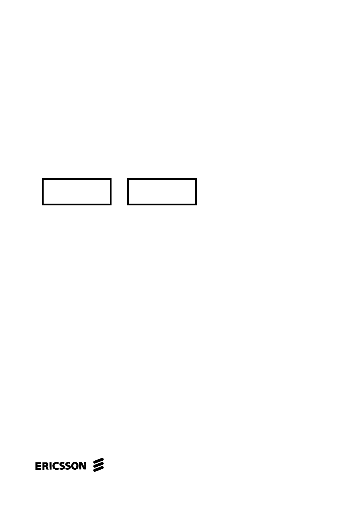
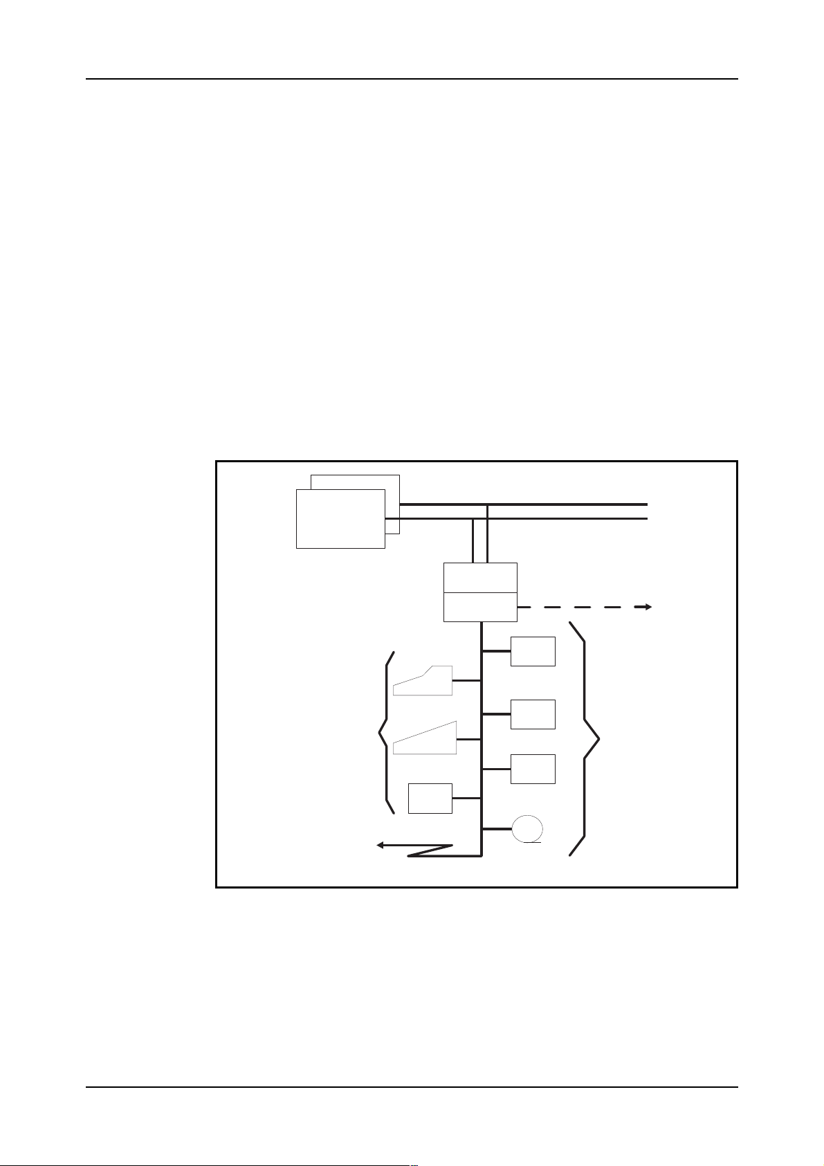
The above mentioned components are incorporated in IOG 11 as shown in
figure 2.2.
03802-EN/LZM 112 19 R1A 5
Page 11
IO System Basic
CP
DL DL
Figure 2.2
Example of an IOG11
AT
AT
ALI
RPA
SP
RPA
ICB
HD
AT
FD FD
AT
OD
AT
MT MT
Note:ODforIOG11B5/C5
SP
HD
OD
Figure 2.2 shows the standard IOG 11 configuration for the products
IOG 11B/B5 and IOG 11C/C5. The differences between the variants will
be covered later.
The interface to the Regional Processor Bus is called the
RP Bus Adapter
(RPA).
The RPA is basically a regional processor, with its own unique address,
that is adapted to the task of helping the main processor in IOG 11 in its
communication with the CP.
The control unit in IOG 11 is a processor called the
SP
for short.
Support Processor
, or
The IOG11B/C is based upon the Motorola 68010 (CP-3) processor, introduced with APZ 212/211 10 R1, APZ 212 02 R2 and APZ 211 02 R6. The
IOG 11B5/C5 is based upon the Motorola 68030 (CP-5) processor, introduced with APZ P2.
The SP contains a considerable amount of software and has an internal
memory of max 12 megabytes (Mb) for IOG 11B/C and 32 Mb for
IOG 11B5/C5. Furthermore, a large amount of data required by the SP is
stored on the hard disks and used by the SP when required.
6 03802-EN/LZM 11 2 19 R1A
Page 12

Configuration of IOG 11 and Hardware Structure
The CP also contains a fairly large amount of software used by IOG 11.
We will look at this later on when the different subsystems of IOG 11 are
examined.
As can be seen, the RPA and SP are duplicated in the standard IOG 11
configuration. This is done as a precaution against faults (hardware or software) arising in one of the SPs.
The two SPs are connected by a bus called the
The ICB allows data to be transferred between the two SPs. It is an 8 bit
parallel bus and carries data at a maximum nominal rate of 115 kilobytes/s
(kb/s).
The SP is often called
switched data network).
The nodes in the duplicated configuration shown above are designated
Node A
The RPA is also called
The IO devices shown in figure 2.2 are as follows:
AT
•
ALI
•
DL
•
HD
•
FD
•
OD
•
Node B
and
Optical Disk drive
Node
(as it can be used as a node in a packet
.
Link
, as it is a link between the SP and the CP.
Alphanumeric Terminal
Alarm Interface
Data Link
Hard Disk drive
Floppy Disk drive
Inter Computer Bus (ICB)
.
MT
•
The IO devices will be covered in detail in the next section.
An IOG 11 as described above - with two nodes each controlling a number
of IO devices - is called a
An SPG can consist of one unduplicated node, but this is very unusual
with IOG 11A, IOG 11B,and IOG 11C. The product IOMC has a very
compact design and consists of one single node. It is used for very small
exchanges.
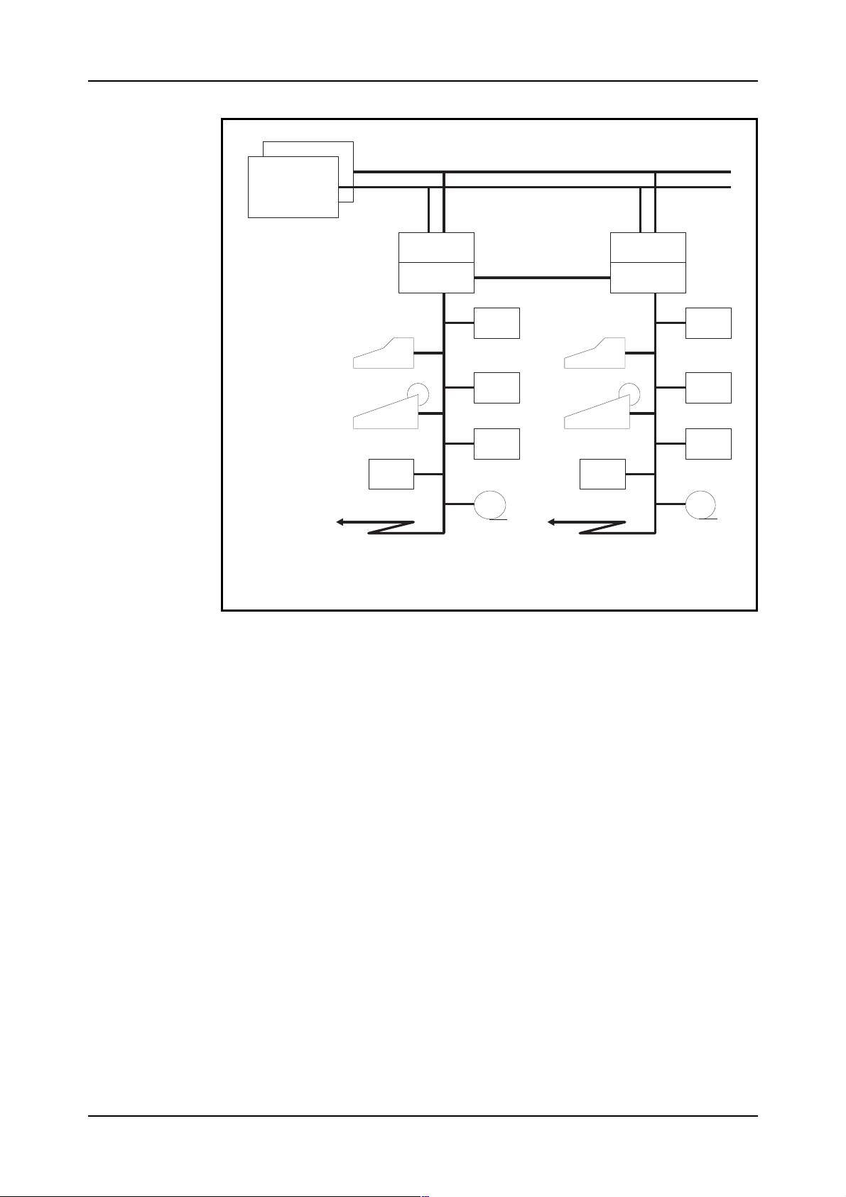
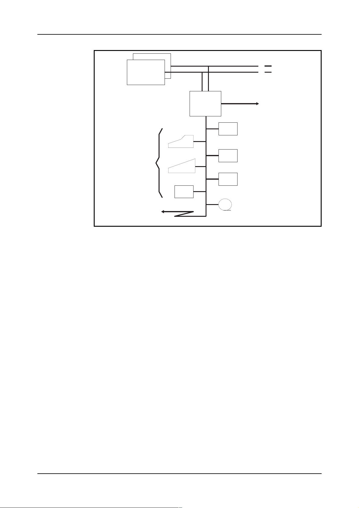
A Support Processor Group is shown in figure 2.3
Magnetic Tape drive
Support Processor Group, SPG
.
03802-EN/LZM 112 19 R1A 7
Page 13
IO System Basic
.
CP-A
CP-B
RPA
SP
RPA
RPB-A
RPB-B
SP
ICB
SPG
Figure 2.3
A Support Processor Group (SPG)
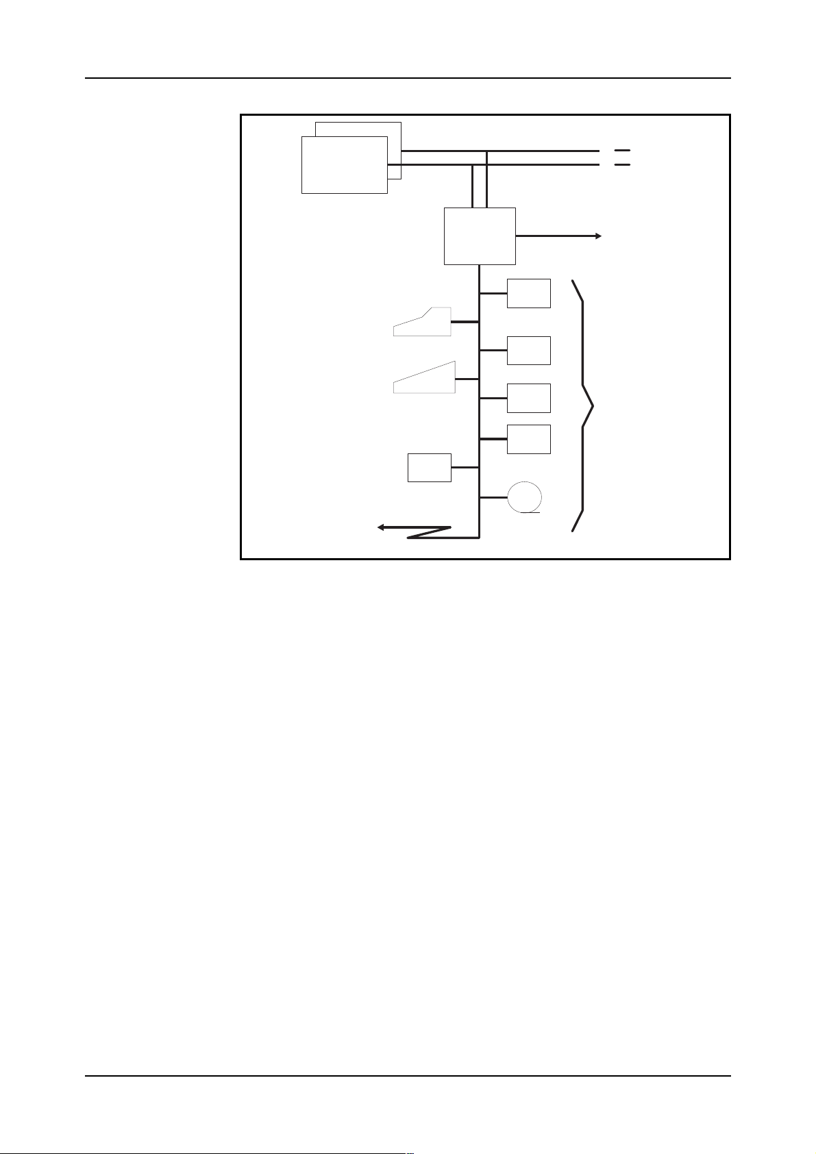
It is possible to connect up to four SPGs to the CP, as is shown in
figure 2.4.
CP
RPB-A
RPB-B
SP SP SP SP
ICB
SPG-0
ICB
SPG-1
ICB
SPG-2
ICB
SPSPSPSP
SPG-3
Figure 2.4
Four SPGs connected to the RP bus
As can be seen from the figure, each SPG is numbered, with the first SPG
being designated SPG-0.
Most AXE exchanges with IOG 11 will require just one SPG, i.e. SPG-0,
whereas exchanges requiring very large amounts of output data storage
and transfer would require two or three SPGs.
SPG-1, SPG-2, and SPG-3 provide basically separate processors for handling such data. They relieve the workload of the SPs in SPG-0 which can
be used to handle the alphanumeric IO devices and alarms.
8 03802-EN/LZM 112 19 R1A
Page 14

IO System Basic
The data stored in these SPGs is norma lly toll ticke ting data a nd statisti ca l
data which is subsequently transferred to remote destinations on high
speed data links or transferred to tape.
We will look more at this later when we examine the different possible
IOG configurations.
In SPG-0, the link at Node A is designated
Link 1
nated
Link 0 has RP address
In the other SPGs the corresponding designations are:
Link 2 (RP-5) and Link 3 (RP-6)
•
Link 4 (RP-7) and Link 5 (RP-8)
•
Link 6 (RP-9) and Link 7 (RP-10)
•
.
RP-1
and Link 1 has RP address
Link 0
and at Node B is desig-
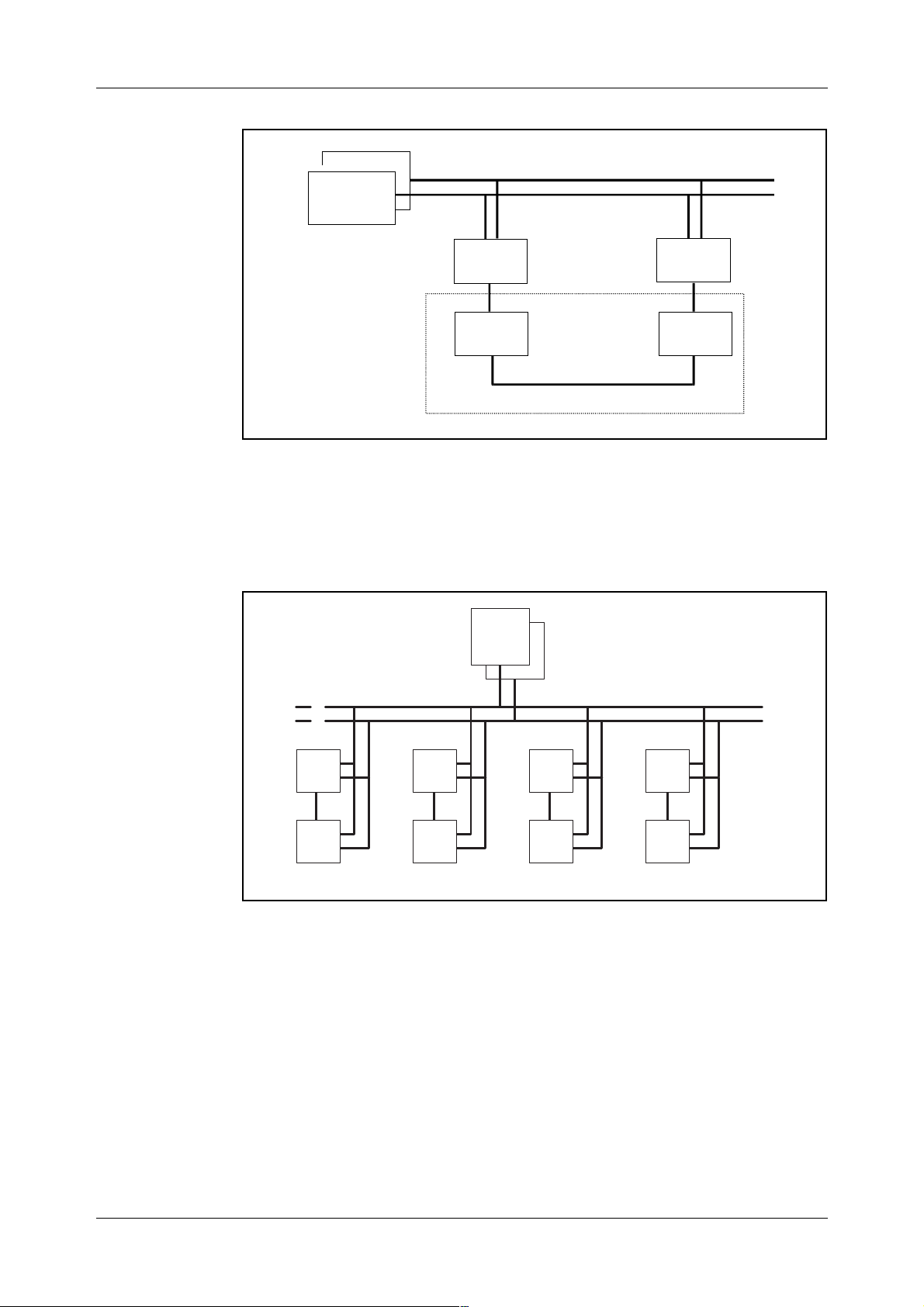
2.2.3 IO Device Functions and Characteristics
The IO devices that we use in IOG 11 have already been mentioned. They
will now be examined in more detail.
Alphanumeric Terminal (AT)
nication. The ATs are used for sending commands and receiving printouts.
An AT can be any type of
computer (PC), a display handler or typewriter . It can also be a line p rinter ,
e.g. the alarm printer is also an AT, as shown in figure 2.5.
PCs and display handlers can, of course, have hardcopy printers
connected.
is the device used for man machine commu-
asynchronous
terminal, normally a personal
RP-4
.
9 03802-EN/LZM 11 2 19 R1A
Page 15
IO System Basic
CP
RPA
ICB
SP
HD
AT
FD
AT
OD
ALI
MT
DL
Figure 2.5
IO devices
Alarm Interface (ALI)
is the interface to which the alarm panels and external alarm sensors are connected. External alarm information is sent to the
SP, and internal and external alarm information sent to the alarm panels,
via this interface.
As we shall see when we look at the hardware configuration, the ALI is
connected to the SP in exactly the same manner as an AT device. It is
regarded as being an AT device and is defined in the data as such.
It should be noticed from figure 2.2 that in the standard configuration the
ALI is usually only found in one IOG 11 side - Node A.
In the SP and CP reference packages, four AT devices are predefined in the
initial data:
AT-0 normal AT for use when SPG has been started
•
AT-1 the alarm interface ALI
•
AT-4 normal AT for use once the IOG has been started
•
(maintenance)
AT-5 as AT-4 (or ALI in node if this exists)
•
If more AT devices are needed they have to be defined by commands and
new hardware has to be installed if necessary. Connecting new AT devices
is covered in the course LZU 108 1452, AXE 10 Operation Handling.
10 03802-EN/LZM 11 2 19 R1A
Page 16

IO System Basic
Hard Disk (HD)
is a mass storage unit type Winchester disk drive consis-
ting of a number of rapidly rotating disks with magnetic surfaces.
The number of disks per drive varies between the different IOG 11
variants leading to different storage capacities, as given below.
Per Hard Disk (HD):
Unformatted Formatted
IOG 11B/B5, IOG 11C/C5 382 Mb 300 Mb
1.27 Gb 1.05 Gb
The HD units are used to store a backup of the SP programs and data, a
backup of the CP software, Command Log and Transaction Log functions,
charging output data and statistical data.
With regard to the hard disks, it should be noted that the CP is always
loaded or reloaded from a HD unit.
Floppy Disk (FD)
is a mass storage unit for replacable diskettes. The dis-
kette size is 5 1/4” and storage capacity is 1.2 Mb when formatted.
Diskettes are used as moveable media. Examples of their use are the loa-
ding of SP software at initial start of IOG 11 and the loading of command
files.
The CP reference dump can also be copied to hard disk from diskettes
prior to initial loading of the CP. However, magnet ic tape is normally more
convenient for this due to the large number of diskettes otherwise required.
Magnetic Tape (MT)
can be used for certain applications where a move-
able medium that can store large amounts of data is required.
It is normally used at initial loading of the CP reference when the
exchange is started for the first time. The reference is c opied from the ta pe
to hard disk before loading. Backups of the CP software can also be stored
on magnetic tape (max 55 Mb). The required backup file on hard disk must
be copied to the tape for this purpose.
MT (max 35 Mb) is also used as a storage for charging data such as toll
ticketing output. The data is first output to hard disk and then transferred
to tape.
MT can also be used as a manual backup function for a data link during
transfer of charging data, or for storing charging data from Operator
Subsystem (OPS) which is first output to HD and then transferred to tape
or data link.
Optical Disk (OD)
(the complete name is Optomagnetic Disk) is a massstorage unit for replaceable disks. The storage capacity of the 5 1/4” disk is
2x297 Mb, when formatted and 2x325 Mb when unformatted.
The OD is readable, writable and rewritable. Writing and rewriting is
realized by using the magnetic material on the disk.
The OD is an optional medium used for backups of reloading data and is
an alternative to MT for large data store sizes.
11 03802-EN/LZM 11 2 19 R1A
Page 17
IO System Basic
The handling of the OD is im portant, therefore the Operational Instruction
should always be followed.
Data Links (DL)
can be used for the connection of remote terminals at an
OMC, and for the transmission of data - e.g charging output or statistics to a processing centre.
2.3 Subsystems in IOG11
The following subsystems belong to IOG 11:
SPS
•
MCS
•
FMS
•
DCS
•
The hardware of each subsystem is shown in figure 2.6.
Support Processor Subsystem
Man-machine Communication Subsystem
File Management Subsystem
Data Communication Subsystem
CP
RPA
SPS
AT
SP
HD
FD
MCS
AT
OD
ALI
MT
DCS
DL
Figure 2.6.
The subsystems of IOG 11
2.3.1 Support Processor Subsystem (SPS)
General
ICB
FMS
SPS implements the program control of the Support Processor, the SP-CP
communication function and maintenance functions for the SP and RPA.
12 03802-EN/LZM 11 2 19 R1A
Page 18

IO System Basic
SPS consists of the following components:
the Support Processors (SPs) with their operating system
•
the Regional Processor bus Adapters (RPAs)
•
software for communication between CP and SP
•
software for operation and maintenance functions for the SPG.
•
SPS interworks with the following subsystems:
Central Processor Subsystem (CPS)
•
Regional Processor Subsystem (RPS)
•
MCS, FMS, DCS
•
Several APT subsystems, for example Statistics and Traffic Measure-
•
ment Subsystem (STS) and Remote Measurement Subsystem (RMS).
(These two subsystems have their software loaded into the SP.)
The SP is an Ericsson designed real time computer called
based on the Motorola M68000 family.
At loading or reloading of an SP, a PROM-stored bootstrap is used to
initiate loading of the SP operating system and software into the primary
memory of the SP from the hard disk. During start up of IOG 11 the software is first transferred to the hard disk from a number of diskettes.
The RPA is the interface unit between the RP bus and the SP, see figure
2.7. It transfers and receives messages to and from the CP.
CP
APN 167
RPB-A
RPB-B
. It is
RPA
SP
ICB
BNA
Figure 2.7
The hardware of SPS
RPA works as a Slave to the SP which has the Master functions.
It consists basically of a microprocessor with its own operating system and
software stored in a PROM memory.
The hardware of SPS is the SP and RPA magazines.
13 03802-EN/LZM 11 2 19 R1A
Page 19

IO System Basic
Bus Network Adapter (BNA)
The
The Software of SPS
The SPS software is situated in the CP, SP and RPA.
In the SP the function blocks of all the subsystems are divided into units
called
called EriPascal.
As mentioned above, the SPS contains the operating system of the SP and
software for handling both CP-SP communication and maintenance of the
nodes and links and a number of SPS operation functions.
CP-SP communication is looked at very briefly below, whereas maintenance functions will be looked at briefly in chapter 3.3 Status of IOG 11
Units.
CP-SP Communication
Communication between the RPA and the CP is in accordance with the
OSI Model for data communication. The OSI Model principles lie outside
the scope of this module and will not be covered here.
modules
. The modules are written in a real time, high level language
is the interface to the ICB in each node.
Communication between the RPA and the SP uses Direct Memory Access
(DMA) which allows the SP to read and write directly from and to the
memory of the RPA.
The CP sees each of the RPAs as an RP and chooses either one when
sending signals to a function block in the SP. This depends on the work
being performed by the CP at that moment.
Normally the CP takes the direct path via the RPA in the executive node
side, but can also access this node via the other RPA over the ICB if necessary. A blocked or separated RPA in the executive node are examples of
such a case. The SP would take the same path for communication in the
opposite direction.
2.3.2 Man-machine Communication Subsystem (MCS)
General
MCS supplies the man-machine interface for operation and maintenance.
MCS handles two types of information:
alphanumeric information (commands, printouts)
•
alarm information (internal, external).
•
The subsystem consists mainly of software - mostly in the CP, but also in
the SP - but some hardware does exist:
the alarm interface (ALI)
•
the alarm panel(s).
•
14 03802-EN/LZM 11 2 19 R1A
Page 20

IO System Basic
MCS interworks with FMS (File Management Subsystem) which provides
storage media for the Transaction Log and for some printouts.
MCS also interworks with SPS and DCS.
This interwork serves three main purposes:
communication between SP and CP for transfer of commands/printouts
•
(SPS)
communication with the terminals (DCS)
•
operation and maintenance of the terminals (DCS).
•
In the above communication the command path is:
SP CP
MCS...............SPS...............SPS...............MCS
The terminal interfaces belong to DCS as will be seen in the section on this
subsystem.
MCS interworks with all command receiving and printout generating
blocks. It also interworks with all program blocks that generate alarms.
The Hardware of MCS
The hardware of MCS consists of the ALI and alarm panels.
The ALI and AT have already been described in chapter 2.2.3 IO Device
Functions and Characteristics. Both the ALI and alarm panel hardware
will be described in chapter 2.4 Hardware Structure.
The ATs - although handled by MCS - do not themselves belong to MCS
(nor any subsystem).
They are physically connected to hardware interfaces belonging to DCS.
15 03802-EN/LZM 11 2 19 R1A
Page 21
IO System Basic
CP
RPB-A
RPB-B
SP
HD
AT
FD
MCS
AT
OD
ALI
MT
DL
Figure 2.8
ALI and the IO devices handled by MCS
2.3.3 File Management Subsystem (FMS)
General
ICB
FMS incorporates hardware and software for handling the external mass
storage of AXE.
The software of FMS is loaded both in the CP and the SP.
The hardware consists of mass storage Winchester hard disks comple-
mented with the file devices for diskette drives, magnetic tape drives and
optical disk drives, see figure 2.9.
16 03802-EN/LZM 11 2 19 R1A
Page 22
IO System Basic
CP
RPB-A
RPB-B
Figure 2.9
The hardware of FMS
DL
AT
AT
ALI
SP
ICB
HD-1
HD-2
FD-1
FMS
OD-1
MT-1
FMS interworks with SPS, MCS, DCS and a number of file users in other
different subsystems.
The Hardware of FMS
The hardware of FMS consists of one Mass Storage Magazine (MSM) per
node in IOG 11B. In IOG 11C the single MSM serves both Node A and
Node B.
In IOG 11B5/C5 the FMS hardware includes also the Optical Disk Magazine (ODM), which contains the Optical Disk drive OD-1.
The MSM contains two Hard Disk drives, HD-1 and HD-2, and one
Floppy Disk drive FD-1 in IOG 11B/B5. In IOG 11C/C5 there is one HD
and one FD per node.
In IOG 11B/B5 two extra Hard Disk drives, HD-3 and HD-4, can be added
to each node (only if 300 Mb hard disks).
The hardware also consists of at least one Magnetic Tape Group (MTG 10)
in IOG 11.
The buses connecting the FMS hardware to the SP (SCSI buses) can also
be included.
17 03802-EN/LZM 11 2 19 R1A
Page 23

IO System Basic
The hardware variants will be covered in chapter 2.4 Hardware Structure.
2.3.4 Data Communication Subsystem (DCS)
General
DCS supplies data communication support for operation and maintenance
applications in AXE 10. DCS is transparent to all data entering or leaving
the IOG via the terminals and data links.
The structure of DCS is based on the OSI model, i.e. a layered structure
for data communication that is in general use today.
It is not necessary to know the principles of the OSI model for normal
operation of IOG 11 and they will not be discussed further here.
DCS resides entirely in the SP, unlike the other three subsystems which
exist in both the CP and SP.
Data from ATs or data links enters the system via DCS functions and is
then transferred to either MCS or FMS within the SP. At start up of
IOG 11, DCS accesses SPS directly.
DCS interworks with SPS, FMS and MCS.
This interwork serves three main purposes:
basic software maintenance of DCS (SPS)
•
storage of DCS dependent data (FMS)
•
operation and maintenance procedures (MCS)
•
DCS offers communication services and provides interfaces to data network users.
It provides network services comparable to a stand-alone
switching
and X.25 networks.
An SP in IOG 11 operates from the DCS point of view as a switch or
Communication Module (CM)
A CM is a logical concept. It defines logically the presence of DCS in the
node (i.e SP). Within an IOG 11 each CM is numbered internally: in
SPG-0, Node A is associated with CM-1, Node B with CM-2. It should be
noted that in SPG-1, Node A is associated with CM-17, Node B with
CM-18 etc.
system, which allows connection to external X.25 equipment
in a packet switched data network.
X.25 packet
To the operation and maintenance engineer the CM concept is only of
importance when designating the hardware interfaces used by DCS. DCS
also provides an alphanumeric terminal interface based on X.28/X.3/X.29
recommendations for the connection of asynchronous terminals to synchronous X.25 equipment.
18 03802-EN/LZM 11 2 19 R1A
Page 24

IO System Basic
The Hardware of DCS
The hardware is realized in the boards of a Line Unit (LU), the only hardware function block in DCS. The LUs contain the interfaces to the alphanumeric terminals and data links.
2.4 Hardware Structure
2.4.1 Introduction
This chapter will explain the differences between the products that exist
today in the IOG 11 family, i.e.:
IOG 11B-S
•
IOG 11B-L2
•
IOG 11B5-S
•
IOG 11B5-L2
•
IOG 11C
•
IOG 11C5
•
IOG 11A and IOMC will not be explained in detail since they are no
longer supplied.
2.4.2 Different SP-Based IO Systems
IOG 11A
IOG 11A was the first release of the new generation of IO, based on APN
167. It was originally named IOG 11 (without “A”).
IOG 11B/B5
IOG 11B/B5 is a more powerful version of IOG 11A with respect to
processor and disk capacity. These two products can be used with most
types of APZ.
IOG 11B/B5 exists in two configurations. The standard configuration,
IOG 11B/B5-S, is used for system back up, command handling, printouts,
file handling, data link output, CP T commands etc. This is used for SPG-0.
IOG 11B/B5-L2 is a subset of the standard version with the functionality
limited to support charging output or corresponding applications. There
are no terminals or alarm functions connected to this configuration. It is
used together with IOG 11B/B5-S. It has the same hardware as the standard configuration except for the alarm interface boards. It is used for
SPG-1, SPG-2 and SPG-3.
IOG 11C/C5
IOG 11C/C5 is a cost-reduced version of IOG 11B/B5. It is intended to be
used for small and medium sized applications, normally when APZ 211 is
used. It has, compared with IOG 11B/B5, less storage capability and fewer
IO-ports for connection of terminals and data links. It fits in one cabinet.
19 03802-EN/LZM 11 2 19 R1A
Page 25

IO System Basic
IOMC
IOMC was a single node compact version with products from IOG 11B
and IOG 11C. It was intended to be used with APZ 211 10 for small sized
applications. IOMC consists of one magazine.
All IO equipment is mounted in BYB 202 cabinets.
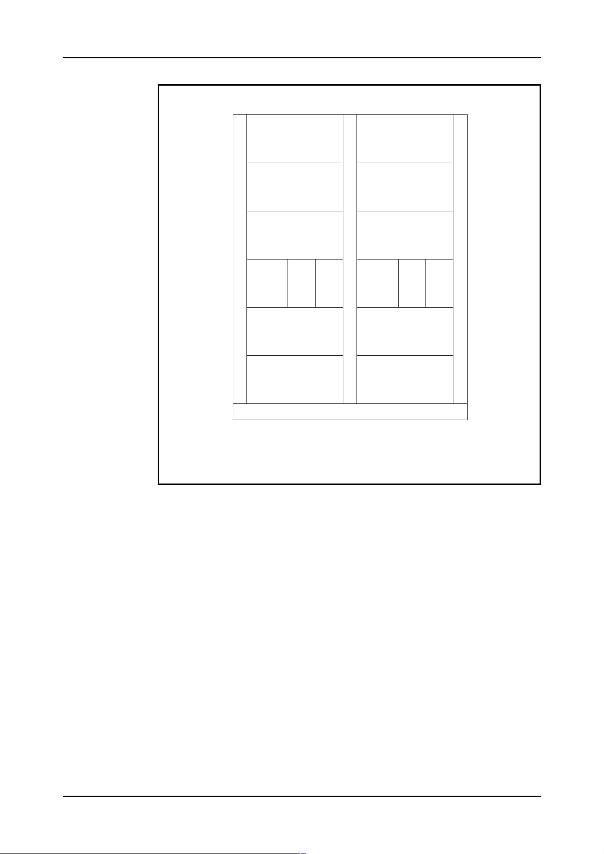
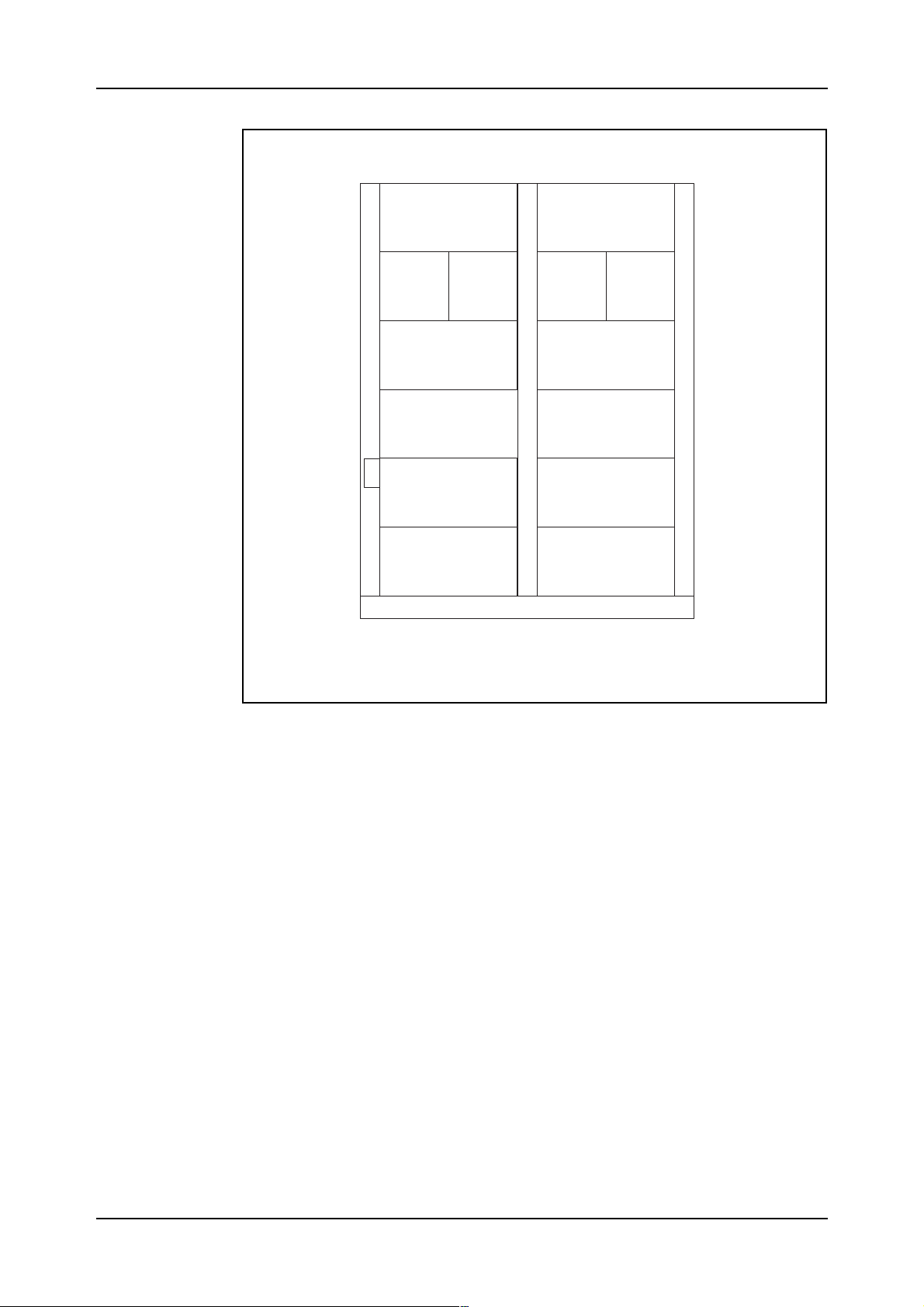
Figure 2.10 shows the cabinet configuration for IOG 11B.
20 03802-EN/LZM 11 2 19 R1A
Page 26
IO System Basic
NodeA NodeB
FAN-A FAN-B
MSM-0-A MSM-0-B
SPSM-A SPSM-B
AL
-A
B-
NAM
-A
RPAM
-B
RPAM
RANG
-A
IOEXT-A IOEXT-B
AL
RANG
-B
B-
NAM
-B
*
MSM-1-A MSM-1-B
Note: NoALRANGinIOG11B-L2
Optional,canbeplacedinMTG10
*)
if5shelfcabinetisused.
Figure 2.10
IOG 11B cabinet configuration
*
The IOG 11B cabinet contains the following magazines except for the air
cooling (FAN) on top of the magazine:
MSM Mass Storage Magazine (FD and HD)
•
SPSM Support Processor Subsystem Magazine (APN 167)
•
RPAM RP bus Adapter Magazine
•
ALRANG ALarm RANGing (external alarms)
•
BNAM Bus Network Adapter Magazine (ICB)
•
IOEXT Input Output EXTension (connection of AT, DL and
•
containing the ALI).
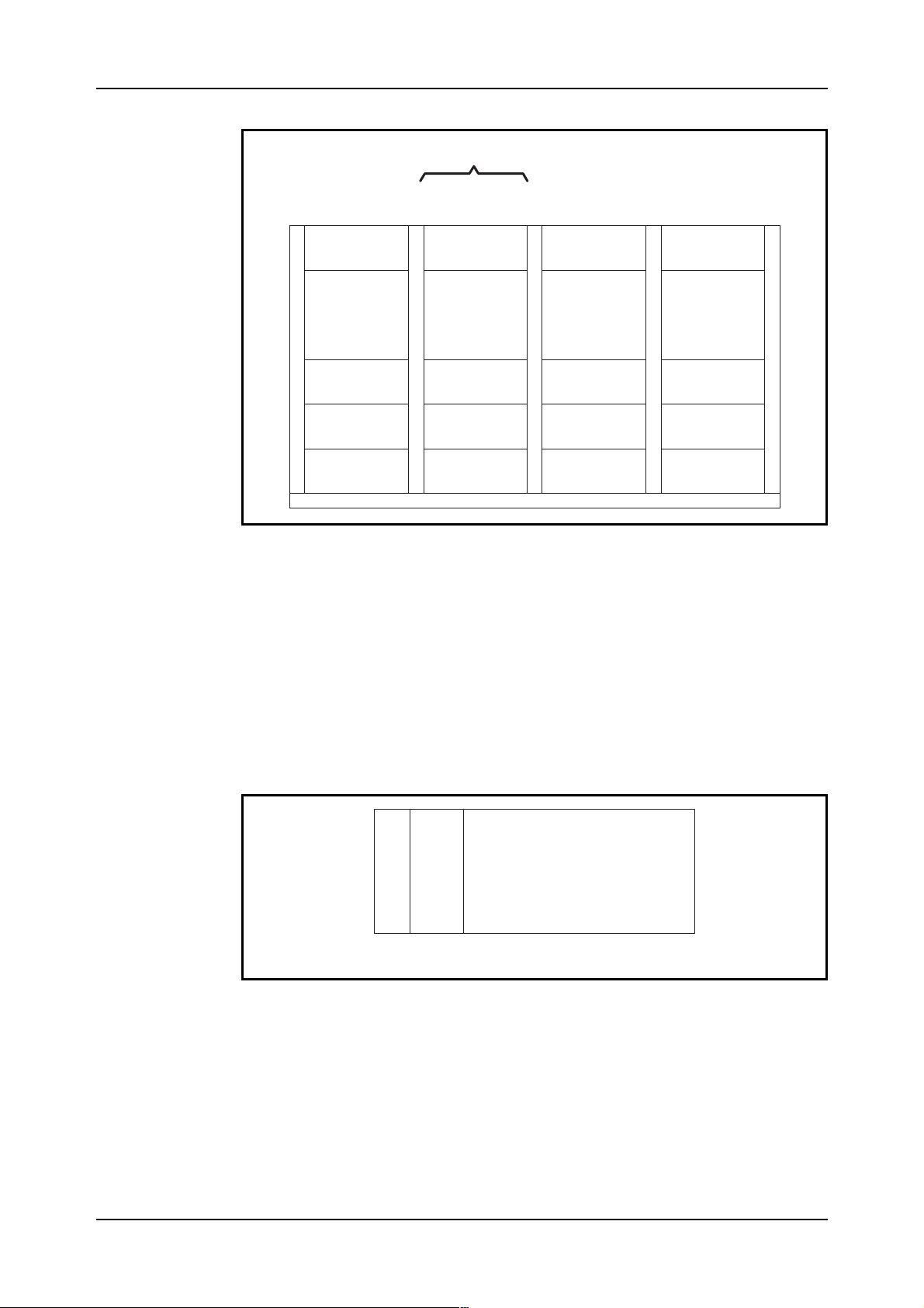
Figure 2.11 shows the cabinet configuration for IOG 11B5.
21 03802-EN/LZM 11 2 19 R1A
Page 27
IO System Basic
NodeA NodeB
FAN-A FAN-B
**
ODM ODM
MSM-A MSM-B
SPSM-A SPSM-B
*
IOEXT-A IOEXT-B
** **
MSM-1-A MSM-1-B
EXRANG
*)
**)
Optional
Note: NoALRANGinIOG11B5-L2
**
Figure 2.11
IOG 11B5 cabinet configuration
The IOG 11B5 cabinet contains the following magazines:
ODM Optical Disk Magazine (OD)
•
MSM Mass Storage Magazine (HD and FD)
•
SPSM Support Processor Subsystem Magazine (APN 167)
•
IOEXT Input Output EXTension (connection of AT, DL and
•
containing the ALI)
EXRANG EXternal RANGing (external alarms).
•
2.4.3 Magnetic Tape Group (MTG 10)
Magnetic Tape units are placed in separate cabinets.
Each SP is capable of handling one MTG 10. Each MTG 10 can consist of
four Magnetic Tape Drives (MTD) but only one is necessary. For security
reasons Ericsson recommend connection of two MTG 10s to an IOG 11,
one to each node.
22 03802-EN/LZM 11 2 19 R1A
Page 28
IO System Basic
Optional
CDR DRR DRR
(Master) (Slave)
FAN
MTD-0
(MT-1) (MT-2)
MTM
Figure 2.12
MTG 10
FAN FAN FAN
MTD-1 MTD-2 MTD-3
The MTG 10 cabinet contains (see figure 2.12):
DRR
A fan unit
•
The Magnetic Tape Drive (MTD)
•
The Magnetic Tape Magazine (MTM) with a power unit and one inter-
•
face board per MTD, TDA-SC, for connection to the IOG 11 (see figure
2.13).
P
TDA-
O
SC
U
MTM
Figure 2.13
The Magnetic Tape Magazine in MTG 10
23 03802-EN/LZM 11 2 19 R1A
Page 29

IO System Basic
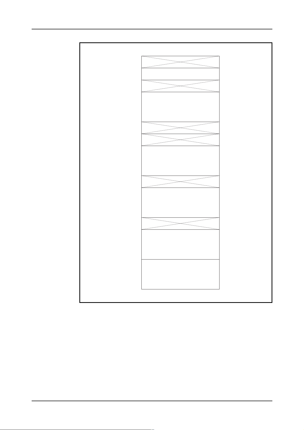
2.4.4 IOG 11B
IOG 11B consists of two nodes, one in each cabinet. It contains the following magazines:
Mass Storage Magazine (MSM)
MSM (see figure 2.14) consists of two hard disk units, one flexible disk
unit, a single interface for all units in the magazine and two power boards.
The capacity of one hard disk is 300 Mb formatted.
MSA-SC Mass Storage Adapter SCSI (SCSI = Small Computer
System Interface)
FDD Flexible Disk Drive
HDD Hard Disk Drive
POU Power Unit
A Mass Storage Magazine with two extra hard disks (no flexible disk
drive) can be added to the system. This magazine is placed at the bottom
of the cabinet. So, the possible configuration of hard disks in each node is
one, two or four.
If 1.05 Gb hard disks are used, see figure 2.32 for the MSM layout.
Note:
24 03802-EN/LZM 11 2 19 R1A
Page 30
IO System Basic
01
02
03
04
07
08
09
10
15
16
17
22
MSA-SC
FDD1
HDD2
HDD1
23
24
POU1 +12V
27
28
POU2 +5V
31
Figure 2.14
The Mass Storage Magazine in IOG11B
25 03802-EN/LZM 11 2 19 R1A
Page 31

IO System Basic
Support Processor Subsystem Magazine (SPSM-2)
The Support Processor Magazine used with IOG 11B is called SPSM-2.
The board positions in the SPSM-2 are shown in figure 2.15.
LMU Local Memory Unit
CPU Central Processor Unit (CP-3)
BNA-I Bus Network Adapter Interface (pos. 13 for RPA,
pos. 17 for ICB)
EBA-SC Extension Bus Adapter SCSI (pos. 14 for FD/HD,
pos. 19 for MT)
BEM-P/S Bus Extension Master Primary/Secondary.
The CPU, BNA, EBA-SC and BEM-P/S boards are interconnected in the
backplane by the
APN-bus
(see also figure 2.20).
The memory boards (LMU) in the primary store have a capacity of 4
Mbytes each which gives the total primary store a capacity of 12 Mb.
The CPU consists of a double board. The processor in IOG 11B (CP-3)
provides 80% more processing power compared to IOG 11A.
The BEM boards are involved in the cross connection between the SPSM
and IOEXT magazines in both nodes (see figure 2.19)
26 03802-EN/LZM 11 2 19 R1A
Page 32

IO System Basic
.
01
02
03
04
05
06
07
08
09
10
11
12
13
14
15
DC/DC +5V
Converters
LMU2
LMU1
LMU0
CPU
CPU
BNA-I
EBA-SC
BEM-S
+
-
12V
16
17
18
19
20
21
22
23
Figure 2.15
BEM-P
BNA-I
EBA-SC
The Support Processor Subsystem Magazine in IOG 11B (SPSM-2)
27 03802-EN/LZM 11 2 19 R1A
Page 33

IO System Basic
RP-bus Adapter Magazine (RPAM)
RPAM (see figure 2.16) contains the RPA which is the interface towards
the RP-bus and helps handle the communication between the CP and the
SP.
RPBU-A RP-Bus Unit A
RPBU-B RP-Bus Unit B
RIB Register In Buffer
ROB Register Out Buffer
TRU Transfer Register Buffer
DBH Data Buffer Handler
BUF Buffer
PRO Processor
01
02
03
04
05
06
07
08
09
10
11
DC/DCConv. +5V
RPBU-A
RPBU-B
RIB
ROB
TRU
DBH
BUF
PRO
Figure 2.16
The RP-bus Adapter Magazine in IOG 11B
28 03802-EN/LZM 11 2 19 R1A
Page 34

IO System Basic
Alarm Ranging (ALRANG)
ALRANG is a magazine without any boards, only a backplane- i.e it has
no logic circuits. It is an interconnection unit for connecting external alarm
sensors. Cables from the alarm sensors and from boards in the ALI in the
IOEXT magazine are plugged in and connected together here. It is used
since there is not enough physical space for 32 connectors on the ALI
boards. ALRANG is normally needed in one side only (Node A).
Bus Network Adapter Magazine (BNAM)
BNAM is the interface towards the bus between the two nodes, the Inter
Computer Bus (ICB). The BNAM is connected by a bus to the SP. The
ICB is connected to the board in position 4 in BNAM (see figure 2.17).
BNALBus Network Adapter Line processor
01
DC/DCConv. +5V
02
03
BNAL
04
05
Figure 2.17
The Bus Network Adapter Magazine in IOG 11B
Input Output EXTension magazine (IOEXT)
The IOEXT magazine contains an interface board (BES) towards the
SPSM in each node, i.e. it is the other end of the cross connection
mentioned earlier. It also contains the boards used for connection of terminals and data links. These are contained in
IOEXT magazine also contains boards for alarm functions in the ALI.
The IOEXT magazine can contain a maximum of four LUs depending on
the configuration. A LU consists of a Regional Processor Unit (RPU) and
either one or two Line Interface Unit (LIU) boards. Figure 2.18 shows
different possible configurations for the magazine.
Line Units (LU)
. In SPG-0, the
BES Bus Extension Slave
RPU Regional Processor Unit
LIU1 Line Interface Unit (up to 19.2 kbit/s)
LIU4 Line Interface Unit (up to 64 kbit/s)
LIA-TTL Line Interface Adapter
29 03802-EN/LZM 11 2 19 R1A
Page 35

IO System Basic
ADAP2L Line Interface Adapter
ALAMP Alarm Panel
ALADIN Additional Alarm Panel
ALEX Additional Alarm External
SCAN Scanning
SPGA Support Processor Group Adapter
10
11
12
13
14
15
1
4
5
6
7
8
9
RPU
LIUx
LIUx
RPU
POU
POU
BES
RPU
LIU1
LIU1
RPU
LIUx
LIUx
LU3
RPU
LIU4
LIATTL
LU3
RPU
LIUx
LIUx
RPU
LU1
LU2
LU3
16
17
18
19
20
21
22
23
LIUx
LIUx
ALAMP
ALADIN
ALEX
SCAN
SPGA
LU4
ADAP2L
LIU4
LIATTL
ADAP2L
x=1or4
LU4
Figure 2.18
The IOEXT-2 showing alternative Line Unit Configuration
30 03802-EN/LZM 11 2 19 R1A
Page 36

IO System Basic
The interface board
BES
is used for the cross connection between the
IOEXT and SPSM magazines in both nodes, see figure 2.19.
SPSM-A BEM(CM1) SPSM-B BEM(CM2)
PS PS
IOEXTA BES IOEXTB BES
Figure 2.19
The cross connection
RPU
The
contains software for the interface and protocols provided by the
LU. The LIU is the board at which the terminal or data link is physically
connected.
Two types of LIU board exist,
LIU1
and
LIU4.
Four asynchronous terminals or low speed data links (maximum 19.2 kbit/
s) can be connected to each of the two LIU1 boards.
Two high speed data links (maximum 64 kbit/s) can be connected to each
of the two LIU4 boards.
31 03802-EN/LZM 11 2 19 R1A
Page 37

IO System Basic
LIA-TTL
The
and the
vided by the LIU4 board for
ADAP2L
PCM
boards are used to adapt the interface pro-
(Pulse Code Modulation) data links.
LIA-TTL is used for adaptation to the TTL-level and ADAP2L is used for
adaptation between the V24 interface and PCM. These boards are only
required for high speed data links using PCM as the transport media.
With the PCM interface only one LIU4 board can be used and only one
data link can be connected. The data link is physically connected to the
ADAP2L board.
On LIU1 there are four positions for the ports at which terminals
and/or data links are connected. (Positions A*1 to A*4).
The ports are numbered 1, 2, 3 & 4 on the first LIU1 board and 9, 10, 11 &
12 on the second board.
The type of connection can be a terminal or a data link for this board, but if
mixed the connections must be made in pairs, i.e. two data links then two
terminals or vice versa.
On LIU4 there are two positions for ports (positions A*1 and A*3).
The ports are numbered 1 & 2 on the first LIU4 board and 3 & 4 on the
second board.
As figure 1.18 shows, the IOEXT magazine can be equipped in different
ways.
The RPUs are always located at positions 6, 9, 12 and 15.
IOEXT-2 is the standard IOEXT magazine of IOG 11B/B5-S.
In this configuration the magazine can be equipped with four LUs contai-
ning either one or two LIU1 boards. It also contains the ALI.
IOEXT-3 is an optional configuration in IOG 11B/B5-L2. Standard
configuration as IOEXT-2, but with LIU4 in board position 7. It can contain maximum three LUs each containing one LIU4 board and the two
adapter boards LIA-TTL and ADAP2L (positions 15&16, 18&19, 21&22)
for PCM data links, but can be reconfigured for other types of high speed
links.
ALAMP
The
board handles the alarm panel interface and the connection of
sensors for eight external alarms. ALAMP is connected as a terminal to an
LIU board.
For additional alarm panels, the board
Additional external alarms sensors are connected to the board
ALADIN
is used.
ALEX
via
ALRANG.
With the help of the board
SCAN,
all alarms initiated in the system can be
scanned by external equipment.
32 03802-EN/LZM 11 2 19 R1A
Page 38

IO System Basic
The information connected by SCAN is sent to an Operation and Maintenance Centre via a data link connected directly to the board. The information can also be monitored in the exchange by a display containing LEDs
called ACU, connected between the SCAN board and the modem.
Sixty-six channels are available on the data link: four alarm classes multiplied by sixteen alarm categories plus one channel for system alarm status
and one for attendance information.
Each of the boards ALAMP , ALADIN, ALEX and SCAN is connected by
a bus.
SPGA
supplies the alarm panels with power via the alarm interface, ALI.
Figure 2.20 shows a more detailed picture of IOG 11B hardware.
33 03802-EN/LZM 11 2 19 R1A
Page 39

IO System Basic
RPB
MDF
MSM-0
LMU
APN- bus
MSM-1
MSA-SC
(Optional)
EBA-SC
BEM
BNA-I
BNA-L
BNAM
MTG10DRR
NodeB
RPA
RPAM
MTG10CDR
TDA-SC
EBA-SC
BNA-I
CPU
SPSM
ICB
ICB
BES
IOEXT
MODEM
LIU1
MDF
MDF
LIU1
RPU
RPU
LIU4
MODEM
MODEM
3
ALD
ALD
1
4(3)CATEGORIES
3
ALD
ALD
AIL
ALD
ALAMP
1
BNAM
LMU
CPU
NodeA
A
RPA
RPAM
B
MTG10DRR
SPSM
BNA-I
MTG10CDR
EBA-SC
TDA-SC
APN-
bus
(Optional)
MSM-1
EBA-SC
MSA-SC
MSM-0
Figure 2.20
IOG 11B hardware block diagram
BNA-L
BNA-I
BEM
BES
IOEXT
LIU4
LIA-TTL
LIU1
LIU1
RPU
RPU
RPU
LIU4
ADAP2L
PCD-D
ALAMP
ALRANG
ALADIN
1CATEGORY4(3)
ACU
SCAN
ALEX
FAN
Ext.at.
MODEM
MDF
34 03802-EN/LZM 11 2 19 R1A
Page 40

IO System Basic
2.4.5 IOG 11B5
IOG 11B5 consists of two nodes, one in each cabinet. It contains the
following magazines.
Mass Storage Magazine (MSM)
When 300 Mb hard disks are used (see figure 2.14) for MSM layout and
when 1,05 Gb hard disks are used (see figure 2.32).
Optical Disk Magazine (ODM)
The ODM (see figure 2.21) contains the Optical Disk (OD) unit (2x297
Mb), one Bus Interface Connection (BIC) board and two power units.
Each ODM is connected to the SP (EBA-SC) via an SCSI bus connected
to BIC board.
B
I
OD
C
Figure 2.21
The OD Magazine in IOG 11
Support Processor Subsystem Magazine (SPSM-6)
The Support Processor Magazine used with IOG 11B5 is called SPSM-6.
The board positions in the SPSM-6 are shown in figure 2.22.
RPBU RP-Bus Unit
RIB Register In Buffer
ROB Register Out Buffer
TRU Transfer Register Buffer
DBH Data Buffer Handler
BUF BUFfer
P
O
U
P
O
U
PRO PROcessor
BNA-I Bus Network Adapter Interface
CPU5 Central Processor Unit Type 5
BEM-P/S Bus Extension Master Primary/Secondary
EBA-SC Extension Bus Adapter SCSI
BNA-L/D Bus Network Adapter Line/Data processor
35 03802-EN/LZM 11 2 19 R1A
Page 41

IO System Basic
000
008
016
024
030
036
042
048
056
062
078
074
080
096
104
112
120
128
RPBU
RPBU
R1B
ROB
TRU-2
DBH-2
BUF
PRO
BNA-I
CPU
(CP-5)
BEM-P
BEM-S
EBA-SC
BNA-I
BNA-L
BNA-D
144
162
178
EBA-SC
POU
POU
Figure 2.22
The SPSM-6 Magazine
As it can be seen from figure 2.22 the SPSM contains the RPA (RPBU,
RIB, ROB, DBH-2, TRU-2, PRO, BUF and BNA-I), APN 167 processor
CP-5, interface towards HD, OD and MT (EBA-SC), towards IOEXT
(BEM) and towards SPSM-B (BNA-I and BNA-LD).
The primary memory is 32 Mb and is located on the CPU (CP-5) board.
The processing capacity in IOG 11B5 (CP-5), is increased by more than
100% compared to IOG 11B (CP-3).
36 03802-EN/LZM 11 2 19 R1A
Page 42

IO System Basic
Input Output EXTension magazine (IOEXT)
The same as in IOG 11B, see figure 2.18.
2.4.6 EXternal RANGing (EXRANG)
EXRANG is an interconnection unit for external alarms and is placed in
the vertical cable runway opposite the IOEXT magazine. It replaces
ALRANG in IOG 11B.
Figure 2.23 shows a more detailed picture of the IOG 11B5 hardware.
37 03802-EN/LZM 11 2 19 R1A
Page 43

IO System Basic
A
B
.
.
AIL
FAN-A,B
3
1
1 cat
ALD
4
ALD
ALADIN
SCAN
ALEX
ALD
ALD
ACU
MOD or MDF
MOD or MDF
MODEM
MODEM
LIU 1
LIU 4
RPU
RPU
BES
DU
INV
PR
LIU 1
DU
DU
INV
IOEXT-B
PC
INV
PR
RPAM-A
GS
DU
DU
4 cat
3
ALD
INV
INV
PCD-D
PCM-MUX
PR
LIU 4
LIA-TTL
ADAP2
RPU
CPT
MAUM
LIU 4
RPU
1
PC
LIU 1
ALD
ALAMP
RPU
BES
IOEXT-A
EXRANG
Ext. al.
TRU-2
DBH-2
BIC
OD
RPBU
ROB
RIB
RPBU
A
RPB
RPBU
ROB
RIB
TRU-2
DBH-2
PRO
BUF
BNA-I
BEM
EBA-SC
CP5
EBA-SC
BEM
CP5
BNA-I
BNA-L,D
BNA-L,D
BNA-I
EBA-SC
EBA-SC
BUF
PRO
BNA-I
RPBU
B
SPSM-A
SPSM-B
RPB
TDA-SC
MT
MTG 10 DRR
Figure 2.23
MT
MTG 10 CDR
BIC
OD
ODM-A
BIC
MSM-A
HD
MSA-SC
FD
BIC
MSM-B
HD
MSA-SC
FD
ODM-B
IOG 11B5 hardware block design (1.05 Gb HDs)
38 03802-EN/LZM 112 19 R1A
Page 44

IO System Basic
2.4.7 IOG 11C
IOG 11C consists of one cabinet, see figure 2.24.
MSM Mass Storage Magazine
SPSM Support Processor Subsystem Magazine
IOEXT Input Output Extension
EXRANG External Alarm Ranging
FAN
MSM
-A -B
SPSM-A
SPSM-B
*
*)EXRANG
Figure 2.24
IOG 11C cabinet configuration
IOEXT
-A -B
Mass Storage Magazine (MSM2)
The Mass Storage Magazine in IOG 11C (see figure 2.25) is called
MSM-2. It has space for one hard disk with 300 Mb or 1.05 Gb capacity
and one flexible disk drive per node. It also contains one interface board
for both HD and FD.
39 03802-EN/LZM 11 2 19 R1A
Page 45

IO System Basic
NodeA NodeB
M
C
M
S
A
-
S
HD
Figure 2.25
FD
P
P
P
P
O
O
O
O
U
U
U
U
FD HD
S
A
-
S
C
The Mass Storage Magazine in IOG 11C (MSM-2)
MSA-SC Mass Storage Adapter SCSI
HDD Hard Disk Drive
FDD Flexible Disk Drive
POU Power Unit
Support Processor Subsystem Magazine (SPSM-5)
The Support Processor Subsystem Magazine in IOG 11C (see figure 2.26)
is called SPSM-5. It contains the RP-bus adapter, the APN 167 processor
and interface boards towards other magazines.
The primary memory boards (LMU) have a capacity of 4 Mb per board
which gives a total primary memory of 12 Mb.
R
R
T
D
B
P
B
R
R
P
P
B
B
U
U
I
O
B
B
Figure 2.26
R
B
U
U
H
F
O
-
2
2
L
L
L
R
N
M
M
M
A
U
U
U
I
The Support Processor Subsystem Magazine in IOG 11C (SPSM-5)
B
C
C
B
E
B
B
B
E
P
P
E
P
P
E
B
N
N
N
B
O
O
M
U
U
M
A
A
A
A
A
U
U
-
-
-
-
-
S
P
P
S
C
-
-
-
S
I
L
D
S
C
40 03802-EN/LZM 11 2 19 R1A
Page 46

IO System Basic
RPBU RP-Bus Unit
RIB Register In buffer
ROB Register Out Buffer
TRU-2 Transfer Register Buffer-2
DBH-2 Data Buffer Handler-2
BUF Buffer
PRO Processor
BNA-I Bus Network Adapter Interface (first BNA-I board is for
RPA, second is for ICB)
LMU Local Memory Unit
CPU3 Central Processor Unit Type 3
BEM-P Bus Extension Master Primary
BEM-S Bus Extension Master Slave
EBA-SC Extension Bus Adapter SCSI
BNA-L Bus Network Adapter Line interface processor (ICB)
Input Output Extension (IOEXT-4)
The IOEXT magazine for IOG 11C (IOEXT-4) can, like the IOEXT magazine for IOG 11B, be equipped in different ways, see figure 2.27.
41 03802-EN/LZM 11 2 19 R1A
Page 47

IO System Basic
000
016
024
030
038
044
050
058
064
072
080
088
094
POU
POU
BES
RPU
LIU1
LIU1
RPU
LIUx
RPU
LIUx
LIUx
ALAMP
ALEX
LU2
LU3
RPU
LIU4
LIA TTL
ADAP2L
LU1
A-node
x=1or4
LU2
ALI
100
106
112
120
126
132
140
146
154
162
170
BES
RPU
LIU1
LIU1
RPU
LIUx
RPU
LIUx
POU
POU
LU2
LU3
Figure 2.27
IOEXT-4 configuration
LU1
RPU
B-node
LIU4
LU2
LIA TTL
ADAP2L
42 03802-EN/LZM 11 2 19 R1A
Page 48

IO System Basic
BES Bus Extension Slave
RPU Regional Processor Unit
LIU Line Interface Unit
LIATTL Line Interface Adapter
ADAP2L Line Interface Adapter
ALAMP Alarm Panel
ALEX Additional Alarm External
For the function of these boards see IOEXT magazine for IOG 11B.
External Alarm Ranging (EXRANG)
EXRANG is an interconnection unit for external alarms with the same
function as ALRANG in IOG 11B. It is placed in the cable chute.
Figure 2.28 shows a more detailed picture of IOG 11C hardware.
43 03802-EN/LZM 11 2 19 R1A
Page 49

IO System Basic
RPB
EBA-SC
BNA-I
BNA-L,D
BEM
ICB
MODorMDF
AIL
ALD
LIU1
ALAMP
MODEM
LIU1
LIU1
CPU
DBH-2 TRU-2
PRO
MTG10CDR
APN-bus
BUF BNA-I LMU
MSA-SC
MSM-B
TDA-SC
NodeB
SPSM
MSM-A
MTG10DRRSPSM
RPBU RIB ROB RPBU
MSA-SC
ICB
BES
IOEXT-A
BUF BNA-I
BEM EBA-SC
EBA-SC
CPU
BNA-I
LMU
BNA-L,D
APN-bus
PRO
NodeA
DBH-2 TRU-2
RPBU RIB ROB RPBU
A
B
RPUPCD-D
BES
ALEX
RPULIU4
LIA-TTL
ADAP2L
IOEXT-B
PCM-MUX
GSD
EXRANG
FAN
Ext.at.
RPU
MODEM LIU4 RPU
MODorMDF
Figure 2.28
IOG 11C hardware block diagram
44 03802-EN/LZM 11 2 19 R1A
Page 50

IO System Basic
2.4.8 IOG 11C5
IOG 11C5 consists of one cabinet, see figure 2.29.
FAN-A
**
ODM
MSM
-A
SPSM-A
SPSM-B
*
IOEXT
-A
Figure 2.29
IOG 11C5 cabinet configuration
-B
-B
*)
**)
EXRANG
Optional
ODM Optical Disk Magazine (for description see figure 2.21)
MSM Mass Storage Magazine (for description see figure 2.32)
SPSM Support Processor Subsystem magazine (for description
see figure 2.22)
IOEXT Input Output EXTension magazine (for description see
figure 2.27)
EXRANG EXternal RANGing (for description see chapter 2.4.6
External Ranging)
Figure 2.30 shows a more detailed picture of IOG 11C5 hardware.
45 03802-EN/LZM 11 2 19 R1A
Page 51

IO System Basic
A
B
F
F
GS
PCD-D
IOEXT-A
INV
PCM-MUX
LIA-TTL
ADAP2
DU
MOD or MD
INV
PC
PR
LIU 1
LIU 4
ALD
ALAMP
AIL
ALEX
RPU
BES RPU
EXRANG
FAN
Ext. al.
MOD or MD
MODEM
LIU 4
RPU
BES
MODEM
LIU 1
RPU
INV
PR
LIU 1
DU
INV
PC
PR
BIC
OD
TRU-2
DBH-2
RPBU
ROB
RIB
RPBU
A
RPB
RPBU
BUF
BEM
ROB
RIB
TRU-2
DBH-2
PRO
CP5
EBA-SC
BNA-I
BNA-L,D
BNA-L,D
BNA-I
EBA-SC
BEM
CP5
BNA-I
EBA-SC
EBA-SC
BNA-I
BUF
PRO
RPBU
B
SPSM-A
SPSM-B
RPB
TDA-SC
MT
MT
MTG 10 DRR
MTG 10 CDR
MSM-A
HD
MSA-SC
FD
MSM-B
MSA-SC
FD
HD
ODM
Figure 2.30
IOG 11C5 hardware block diagram
46 03802-EN/LZM 112 19 R1A
Page 52

IO System Basic
2.4.9 LEDs and Buttons
In the IOG hardware there are a number of lamps (LEDs) indicating different states and faults that can occur in an IOG, see figure 2.31.
In the CPU (CP-5) board there are two leds, two toggle switches and two
push buttons. For explanations see figure 2.31.
In the CPU (CP-3) board in IOG 11B and C there are two LEDs, see figure
2.31. The meaning of these LEDs is as follows:
GREEN YELLOW
OFF OFF CPU not responding
OFF ON After power on or reset. The status
is set by the hardware. CPU and
memory tests are started. Memory
test = 1-5 minutes.
OFF FLASHING If self-test fails
ON ON Restart/Reload in progress
ON OFF Tests have been completed with no
errors. The Bootstrap program boots the
system. The booted system has
started and the file-loaded modules
are ready to run. This is the NORMAL
indication status.
There are also two push buttons on the CPU (CP-3) board front. These
buttons should only be used in special situations. The upper button is for
debugging of SP programs. It must not be pushed during normal operation.
The lower (reset button) is for restarting (press once) or reloading (press
twice) of the SP.
A terminal can be connected straight in to the SP on the CPU board. This
is referred to as a
local terminal
. From this terminal only SP commands
can be sent.
A local terminal is, for instance, used at initial start of IOG 11.
Normally an IO switch is used through which one terminal is connected to
both the CPU port and a normal IO port.
For CP-5 the terminal is connected at position 080A*4F in the SPS maga-
zine, and for CP-3 at position 12B*4F.
With the push button on the PRO board in the RPA the link can be sepa-
rated before loading the CP. The push button is optional and if it does not
exist, the link can be separated by switching off and on the power in the
RPA Magazine.
47 03802-EN/LZM 11 2 19 R1A
Page 53

IO System Basic
Figure 2.31
Leds and buttons
48 03802-EN/LZM 11 2 19 R1A
Page 54

IO System Basic
2.4.10 1.05 GBytes Hard Disk
A new hard disk was introduced for IOG 11B/B5 and IOG 11C/C5. This
hard disk media will in the near future replace the current 300 Mb hard
disk.
The storage capacity of the new hard disk is 1.05 Gb formatted (unformatted 1.27 Gb).
A maximum of 16 volumes starting on one hard disk is allowed. However,
the maximum allowable number of volumes in an SPG is 16.
Figure 2.32 shows the layout of the Mass Storage Magazine in
IOG 11B/B5 with the new hard disk.
Since this hard disk is SCSI based, there is no need for an MSA-SC
(Mass Storage Adapter SCSI) board as an interface between the hard disk
and the corresponding hard disk drive. The MSA-SC board must still be
included in the system as an interface to the FD.
The hard disk is backplane connected, i.e. no front cable connections,
exist.
The BIC (Bus Interface Connection) board in MSM is front connected to
the EBA-SC board in SPS Magazine and is also front connected to the
MSA-SC in MS Magazine.
In IOG 11C/C5 the hard disk is front connected to the EBA-SC board in
the SPSM and is also front connected to the MSA-SC board in the MSM.
49 03802-EN/LZM 11 2 19 R1A
Page 55

IO System Basic
01
02
03
04
07
08
09
10
15
16
17
21
BIC
MSA-SC
FDD1
HDD2
HDD1
22
23
24
POU1 +12V
27
28
POU2 +5V
31
Figure 2.32
The Mass Storage Magazine in IOG 11B/B5
50 03802-EN/LZM 11 2 19 R1A
Page 56

IO System Basic
2.5 Chapter Summary
IOG 11 is a
•
the processor that controls the IO system. It exists in several variants
and we have described IOG 11B/B5 and IOG 11C/C5 in this module.
The main functions for the IOG 11 are to handle data, store data and
•
handle alarms.
For connection to the RP bus, the IOG 11 has an interface called the
•
Regional Process Adapter
designated a RP-number.
The SP is also called a
•
are duplicated. Together, they form a
One IOG 11 can consist of four SPGs.
The storage media for IOG 11 are
•
Magnetic Tape
For man-machine communication we connect
•
(AT) to the SP. The
connection of external alarms and the alarm panel(s), is connected to
the SP as an AT.
• Data Links
transmission of data, e.g. charging data.
Support Processor
Node
(MT) and
Alarm Interface
(DL) can be used for connection of remote terminals and for
(SP) based IO system, where the SP is
(RPA). The RPA is also called a
. For security reasons the nodes and links
Support Processor Group
Hard Disk
Optical Disk
(ALI), which is the interface for
(OD).
(HD),
Floppy Disk
Alphanumeric Terminals
Link
and is
(SPG).
(FD),
The IOG 11 consists of four subsystems:
•
(SPS),
tion Subsystem
The last part of the chapter gave a description of the hardware structure
•
of the different IOG 11 variants.
File Management Subsystem
(MCS) and
Data Communication Subsystem
Support Processor Subsystem
(FMS),
Man-machine Communica-
(DCS).
51 03802-EN/LZM 11 2 19 R1A
Page 57

IO System Basic
52 03802-EN/LZM 11 2 19 R1A
Page 58

3. Command and File Handling
3.1 Chapter Objectives
Chapter Objectives
After completing this chapter the participant will be able to:
• Explain the purpose of the Entry Commands used with IOG 11.
• Name the entry commands for the four subsystems.
• Explain the difference between accessing the SP in local mode and
accessing in normal command mode.
• Give the reason for accessing the SP in local mode and know how
to enter local mode in two ways.
• Describe the different statuses of the units Link, Node, Line Unit,
Network Port/Physical Port and Alphanumeric Terminal.
• Explain the concepts Executive and Standby in relation to the
nodes in a node pair and describe how the Inter Computer Bus
sends data between the two nodes.
• With a printout of the file attributes of a file, explain the different
parameters that are assigned a file.
• Explain the concept Duplicated Volume and relate the unique
characteristic of all such volumes.
• Describe the contents of the volumes PROG_A/PROG_B,
OMFZLIBORD and RELVOLUMSW.
• Be able to use create, delete, write to, read from and execute a file
with the help of the relevant Operational Instruction.
• Explain the purpose of the File Process Utility function giving the
type of files that are normally transferred by this function.
• Use FPU functions to transfer files from hard disk to magnetic tape
or via data link with the help of the relevant Operational Instruction.
• Dump charging data to hard disk using the relevant Operational
Instruction.
• Set up logging conditions for the MCS Transaction Log and execute searching in the log file with the help of the relevant Operational Instruction.
Figure 3.1
Chapter objectives
03802-EN/LZM 112 19 R1A 53
Page 59

IO System Basic
3.2 IOG 11 Command Handling
When using IOG 11 to enter commands it is necessary to distinguish
between those commands that are owned by function blocks that only e xist
in the CP and those commands which are owned by blocks in the SP. Or,
putting it in a slightly simplified way, one must distinguish between
commands
All commands that are addressed to the CP - for both APT and APZ blocks
- are given in the normal way in accordance with the rules of the
man-machine language. IOG 11 is transparent for these commands and for
the answer printouts received. This is shown in figure 3.2.
SP commands
and
A T SP CP
COMMAND
PRINTOUT
.
CP
Figure 3.2
Command path for CP commands
When a command is to be given to an SP - in any SPG connected to the CP
- the CP must first be told that this is the case. To do this, one must give a
special
entry command
which opens a dialogue between the operator ter-
minal and the required SPG.
The entry command is also called a path building command i.e. it is used
to set up a path from the CP to the required SPG for the following
command sequence. The dialogue is then carried out from the terminal
side using
subcommands
, e.g.
<IMMCT:SPG=0;
This entry command builds a path from the CP to an SP in SPG-0.
Entry commands are analysed in the normal manner by the ANA blocks in
the CP. User authority and terminal authority verification can be
provided by the ANA blocks for these commands.
Each entry command owns a given set of subcommands, so once an entry
command has been given correctly any of these subcommands can be
entered.
The subcommands pass from the SP to the CP where they are directed to
the required SPG. The CP is transparent for these commands i.e. no checks
are made on the subcommands in the CP. The checking is carried out in the
SP.
54 03802-EN/LZM 112 19 R1A
Page 60

Command and File Handling
An exception to the above is the case of some subcommands belonging to
FMS which are processed in the CP from where signals are then sent to
FMS in the SP to execute the required work.
The printouts are sent back to the terminal on the same path, see figure 3.3.
An exception to the above (figure 3.3b) is the special case of certain large
result printouts received from the SP in own SPG. These can be sent
directly to the terminal from the SP without going via the CP in order to
save CP capacity.
A group of MCS blocks in the SP (MESSTRANS, COMANA AND
PRINTSERV) have the same function in the SP as the ANA blocks in the
CP, i.e. perform the necessary interface between the incoming commands/
outgoing printouts and the user blocks.
03802-EN/LZM 112 19 R1A 55
Page 61

IO System Basic
a)
b)
c)
SPG-0
AT CP
AT CP
AT
ENTRY
COMMAND
PRINTOUT
SUBCOMMAND
PRINTOUT
ENTRY
COMMAND
PRINTOUT
SP
SPG-0
SP
SPG-0
SP
SPG-1
SP
CP
d)
Figure 3.3
AT CP
SUBCOMMAND
a) Entry command and printout, own SPG
b) Subcommand and printout, own SPG
c) Entry command and printout, other SPG
d) Subcommand and printout, other SPG
3.2.1 Entry Commands
For each subsystem there is more than one entry command. This is to
enable the system to accommodate users who have different authority
levels with regard to entry of commands.
SPG-0
SP
PRINTOUT
SPG-1
SP
56 03802-EN/LZM 112 19 R1A
Page 62

Command and File Handling
Three dif ferent en try command s exis t for FMS, wh ile DCS an d MCS share
the same three entry commands. SPS has just one entry command.
The commands used for DCS/MCS are general entry commands that
would also be used for addressing functions belonging to Remote Meaurement Subsystem (RMS) and Statistics and Traffic Measurement
Subsystem (STS) if these were loaded.
In each subsystem each command corresponds to a different authority
level: high, middle and low.
High authority entry commands allow all subcommands for the subsystem
to be entered.
Middle authority commands allow a limited number of subcommands to
be entered.
Low authority commands allow only print subcommands to be entered.
The entry commands for each of the subsystems are listed below:
SPS (maintenance) FMS MCS/DCS/
SPS (operation)
IMMCT INMCT IMLCT
INMIT IMLIT
INMPT IMLPT
In the commands:
C
is for Change and Printhigh authority
I
is for Change and Printmiddle authority
P
is for Printlow authority
When an entry command is given correctly, the system answers with a
colon
, see below:
<IMMCT:SPG=0;
:
A subcommand can now be given after the colon.
A further entry command not previously mentioned is the command
ISMCT
.
This is a special entry command which is only used at start up of an
IOG 11 - so called
cold start
.
On starting up the system, initial software is booted into the SP’s CPU
from a diskette and this software allows commands to be entered from a
terminal connected directly to a special port on the CPU board.
This terminal is called a
local terminal
. It is any asynchronous terminal set
to 4800 baud. In IOG 11B5/C5 the terminal is connected at position
03802-EN/LZM 112 19 R1A 57
Page 63

IO System Basic
08-A-04 in the SPS magazine, in IOG 11B/C it is connected at position
12-B-04.
The command ISMCT is then used to allow the use of subcommands for
formatting the hard disks, defining the hard disk volumes and loading the
SP software to the hard disks.
The ISMCT command will only be accepted during the start up phase and
therefore is not used for basic operation and maintenance.
Cold start of an IOG 11 is beyond the scope of this book and will not be
covered further here.
3.2.2 Subcommands
A set of subcommands belongs to each of the entry commands. These are
also found in the Command Descriptions in the B-Module.
When a subcommand is entered with the necessary parameters (if any)
answer printouts are received in exactly the same way as with CP
commands. After each of these printouts a new colon is given so that a
new subcommand can be entered, and so on.
To end the dialogue the subcommand
END
must be given.
After this subcommand the communication returns to the CP and the ready
mark is obtained. Normal CP commands can now be given. A new entry
command must be given if a new sess ion between the CP and an SPG is to
be initiated.
An example of an entry command and subcommands is given in figure
3.4.
Figure 3.4
Example of an entry command and subcommand
58 03802-EN/LZM 112 19 R1A
Page 64

Command and File Handling
:
When the procedure printout
ORDERED
is received in answer to a
subcommand, the dialogue must first be terminated before the terminal can
be released. The subcommand END must be used.
After receiving
EXECUTED
the terminal can be released and the result
printout obtained, see figure 3.5.
Release the terminal to get the result printout
Figure 3.5
Use of END after printout ORDERED
As the dialogue has been terminated, if one wishes to continue with
subcommands belonging to the original entry command then the entry
command must be given again before it is possible to continue.
The above procedure can be speeded up by use of the character @. By
giving this, one interrupts an ongoing dialogue and one leaves the entry
command for temporarily.
This can be done at any time, for instance when it is necessary to give a
command to the CP. To return to the entry command one must release the
terminal.
On receiving ORDERED it is suf f icient to type @ f irst and then re lease the
terminal. As the terminal is released the result printout will be obtained if
the job has already been carried out, followed by a return to the subcommand dialogue.
If the job has not been executed then the result printout will be obtained
next time the terminal is released.
03802-EN/LZM 112 19 R1A 59
Page 65

IO System Basic
3.2.3 Local Mode and CPT Commands
As has been seen so far, all commands concerned with an SP - both entry
and subcommands - are sent to the CP from the SP. The subcommands are
directed by the CP back to the SP or to an SP in another SPG. However,
the possibility exists to send commands to the SP which do not go on to
the CP, but are handled directly by the SP.
To be able to do this, two conditions must be satisfied:
•
the commands must be SP commands, i.e. must belong to user blocks in
the own SP
•
the SP must be accessed by an operator working in
local mode
.
Using local mode the operator talks directly to the SP and receives printouts directly from the SP. This is illustrated in figure 3.6.
AT CP
COMMAND
PRINTOUTS
Figure 3.6
Command and printout paths in local mode
SP
One can access the SP in local mode at any time, even if the CP is running,
but obviously there is no reason to do this. The number of commands that
can be addressed to the SP alone is limited.
The main use of local mode is to be able to access the SP when the CP is
unavailable for some reason.
Should the CP become seriously faulty and IO commands are not
accepted, then access to the system using local mode must be used to
initiate a recovery process.
Within the SP software exists the function block
Test system)
. This software - a number of Maintenance Subsystem
CPT (Central Processor
modules - allows us to access CPT hardware in the CP in order to facilitate
testing and loading of the CP from hard disk.
To do this we must use a set of
CPT commands
. To be able to give CPT
commands the SP must be accessed in local mode.
To use local mode a command is used: MCLOC. Access in local mode can
be made from any terminal having authority for this command.
At loss of contact with the CP for any reason the message
CP Unavailable, Enter EXIT or MCLOC
60 03802-EN/LZM 112 19 R1A
is given.
Page 66

Command and File Handling
The command MCLOC will always be accepted provided that the SP is
running. The sequence is given below:
<MCLOC:USR=usr,PSW=psw;
EXECUTED
<
USR and PSW correspond to the operator’s user name and password
defined in the User Directory.
A master user and password are defined in the initial data but can be
removed by the administration.
Commands can now be given to the support processor in the own SPG. It
should be noted that MCS and DCS subcommands require no entry
command when one is in local mode.
The entry command for these subsystems (IMLCT) is a general entry
command and is not required in local mode. It can be given, however,
without causing any problem.
The subsystem FMS has its own specific entry command and with this
subsystem the entry command must be given when FMS is to be accessed
in local mode.
The subsystem SPS is not accessable from local mode.
Local mode can also be attained by making use of the local terminal
mentioned above. If, for instance, all Line Units are blocked then no
access can be made to the system via the IOEXT magazines.
A terminal connected to the CPU board in the SP could be us ed to give SP
commands to deblock the LUs.
When entering local mode using a local terminal then the command
MCLOC is not required.
All four subsystems can be accessed in this case. the entry commands for
SPS and FMS can be given without the SPG parameter.
The AT must be working with capital letters in this case. If contact is lost
during a command sequence, the terminal must be switched to TTY (teletype) mode and semicolon entered. On reception of the ready mark return
to buffer mode.
An important difference to notice between normal mode and local mode of
access is that when a terminal has to be released in local mode then the
command
EXIT
must be used. To return to local mode the command
MCLOC must be used again.
03802-EN/LZM 112 19 R1A 61
Page 67

IO System Basic
3.3 Status of IOG 11 Units
The path from the CP to an Alphanumeric Terminal can be expressed as
follows:
CP - RPA - SP - LU - NP/PP - AT
CP Central Processor
RPA RP bus Adapter
SP Support Processor
LU Line Unit
NP Network Port
PP Physical Port
AT Alphanumeric terminal
These units can all have different working states as will be seen in this
section.
3.3.1 RPA State
The possible states of an RPA or Link are:
•
Normal (NORM)
•
Separated (SEP)
•
Blocked (ABL, MBL,TBL = Test Blocked)
A separated link is used to communicate with a separated CP-SB, e.g.
during initial loading of the CP or for changes in the CP software (functional change).
A link can be separated by command if the CP is running, or by depressing
the button on the PRO board of the RPA if the CP is not running.
A link can be blocked by command - this will be covered later in chapter
3.3.6 Blocking and Deblocking. It will then have the state manually
blocked (MBL).
An SP-Link Fault will lead to the link being automatically blocked (ABL).
To print link state we use the command
EXSLP
, see figure 3.7.
62 03802-EN/LZM 112 19 R1A
Page 68

Figure 3.7
SP Link Data
3.3.2 Node Configuration Status
The term node has already been used when talking about an SP: i.e. Node
A and Node B being the two SPs in an SPG.
The word node is just another word for SP. The node concept is fundamental to the operation and maintenance of an SPG.
Command and File Handling
The two nodes in an SPG form a
Executive (EX)
ted
and the other
node pair
. One of the nodes is designa-
Standby (SB)
.
The EX/SB configuration with regard to nodes is implemented mainly for
supervision of the nodes in an SPG.
Unlike the case with the CPs, the SPs do not carry out exactly the same
job. In this case the EX node is involved in all the ongoing work in the
IOG. Data dumped from the CP to hard disk (e.g. TT output) passes via
the EX node and all alphanumeric communication goes to/from the CP via
the EX node.
The SB node is used only to store data - receiv ed from the EX node via the
ICB - in the duplicated volumes on hard disk.
The SB node normally only executes programs belonging to FMS as well
as programs in SPS for its own supervision and for checking heartbeat signals sent from the EX node and the CP.
When the SB node is fully operational it is basically idling, ready and
waiting to take over in case of failure in the EX node.
Contrary to the case of the CP, there is no normal state with node A as EX
and node B as SB. Either node can be EX during normal operation, and
will remain so until such time as a fault in that node causes a side switch.
A fault in the EX node will cause this node to switch sides - i.e. order the
SB to become EX - and then initiate a self reload or restart depending on
the type of fault.
A fault in the SB node will cause the EX node to order the SB to initiate a
reload or restart.
03802-EN/LZM 112 19 R1A 63
Page 69

IO System Basic
Each of the two nodes always has a
The EX node always has the status
The EX node usually has the state
status
WORKING
NORMAL
However, the EX node can also have the state
RELOADED
if the SB node is blocked and a fault occurs in the EX side.
state
and a
.
.
RESTARTED
attached to it.
or
The EX cannot then switch sides before initiating a restart or reload.
The SB node can have a series of different status and states depending on
different situations.
When operating normally it also has status Working and state Normal.
The normal status/state for the two nodes is expressed as:
EX / WORKING-NORMAL
SB / WORKING-NORMAL
and
.
To print Node Configuration Status we use the commands given in figure
3.8.
Figure 3.8
Node Configuration Status
To understand the other states of a the SB side, the maintenance procedure
after a fault must be looked at.
Briefly, the situation with a hardware fault is that, after reloading (or
possibly restarting) from its own hard disk, if possible, the SB node will be
ordered by the EX to start a diagnostic test sequence.
It goes through the states:
SB/ISOLATED-RESTARTING
SB/ISOLATED-DIAGNOSING
If the fault is found to remain then the EX node will order the SB to block
itself i.e. attain the state:
SB / ISOLATED-BLOCKED
and an alarm will be issued.
64 03802-EN/LZM 112 19 R1A
Page 70

Command and File Handling
After manual repair of the fault using the relevant Operational Instruction
and deblocking, the node will go through the following states:
SB / ISOLATED-RELOADING
SB / ISOLATED-DIAGNOSING
SB / ISOLATED-UPDATING
SB / WORKING-RELOADED
SB / WORKING-NORMAL
(Reloading of SB node)
(Diagnostics in SB node)
(Updating of HD volumes)
(SB node has reloaded)
(SB node normal again).
If the fault is not found to remain at the first diagnosing, then the SB side
will go through the states UPDATING, RESTARTED and return to
NORMAL again.
If a node is manually blocked for some reason and then deblocked, the
above five states beginning with RELOADING will always be gone
through.
Updating of the hard disks in the SB side means that certain so called
duplicated volumes
on the hard disks are updated via the ICB from the
corresponding volumes on the disks in the EX side.
This is necessary because during the time a node is blocked, reloading and
diagnosing, no new data (e.g. toll ticketing output) can be stored on the
hard disks of that node.
The updating is either a
UPDATING (L)
UPDATING (S).
or
long (L)
or a
short (S)
update:
The type of updating depends on the amount of information that has to be
copied over.
If a relatively small amount of data in the duplicated v ol umes has changed
during the time the SB was blocked then a short updating is sufficient.
This means that only the data that has changed needs to be copied to the
SB side.
If a considerable amount of data has changed, then a long updating is
called for and all the contents of the duplicated volumes are copied over.
The recovery sequence for a software fault is similar to that for the hardware fault above, but shorter as a restart is normally sufficient
(SB / ISOLATED-RESTARTED). Also, the updating of the hard disks is
always only a short update.
A restart of an SP takes about thirty seconds.
The reloading of an SP takes only a short time - about two minutes.
Diagnostics can take several minutes.
A short update takes several minutes.
03802-EN/LZM 112 19 R1A 65
Page 71

IO System Basic
A long update can take sev eral hours: the time depends on the CP type and
on the defined size of the duplicated volumes.
When CP-3 system is used the large updating copies all sectors of duplicated volumes from EX node to SB node, even if the sectors are not used.
When CP-5 system is used, the large updating copies only the used sectors
from the EX node to the SB node.
The state WORKING-RELOADED (or WORKING-RESTARTED) exists
for fiv e mi nutes. This i s a state during which a repaired or deblocked node
is kept under special supervision.
Should a new fault situation occur during this time then the node will not
reload or restart as described above, but will immediately become
ISOLATED-BLOCKED and an alarm will be issued.
This is to prevent cyclical reloadings, diagnosings and updatings in a still
faulty node.
The time taken for a node to restart and go through the states
UPDATING(S), RESTARTED and back to WORKING-NORMAL is
about seven minutes.
The time taken for a node to reload and go through the states
DIAGNOSING, UPDATING(S), RELOADED and back to WORKINGNORMAL depends on the diagnosing time, but would normally be about
ten to fifteen minutes.
During this period, howev er , no operational problems exist as the EX node
handles all the workload of the IOG.
3.3.3 Line Unit Status
Before looking at Line Unit status the designation of Line Units must be
explained.
An LU is designated as follows:
LU = CM - LM - LU
CM= Communication Module
LM= Line Module (= IOEXT magazine)
LU= Line Unit
In the above designation, CM represents the f irst CM i n the CM pair. (The
CM pair corresponds to the node pair). For a normal IOG 11A-C, for all
Line Units in both IOEXT magazines:
if SPG=0, CM is always 1
if SPG=1, CM is always 17
if SPG=2, CM is always 33
if SPG=3, CM is always 49.
LM or Line Module is an older name for IOEXT magazine.
66 03802-EN/LZM 112 19 R1A
Page 72

Command and File Handling
On the Node A side, IOEXT A implies LM=1.
On the Node B side, IOEXT B implies LM=2.
The designation of the third LU in the B Node side in SPG-0 is:
LU = 1 - 2 - 3
A Line Unit can have the following states:
•
Working WO
•
Manually Blocked MB
•
Automatically Blocked AB
•
Hardware Blocked HB
•
Control Blocked CB
To print Line Unit state we use the commands given in figure 3.9.
Figure 3.9
DCS Line Unit Data
3.3.4 Port Data
Ports are designated in the same way as Line Units with the port number
within the LU included in the designation:
PP = CM - LM - LU - PP
NP = CM - LM - LU - NP
Figure 3.10 illustrates the above relationships.
03802-EN/LZM 112 19 R1A 67
Page 73

IO System Basic
IOG1 1(SPG0)
CM1
NodeA NodeB
IOEXTA
(LM1)
CMPAIR
IOEXTB
(LM2)
NP=1 -2 -3 -9
LU1 LU2 LU3 LU4
CM2
LM2
Figure 3.10
Designation of Line Units and Ports
R
P
U
1
2
3
4
L
I
U
1
LU3
10
11
12
9
L
I
U
1
PortNo.9
68 03802-EN/LZM 112 19 R1A
Page 74

Command and File Handling
A Network Port (NP) or Physical Port (PP) can have the same states as a
Line Unit. On definition, a port is manual blocked and on deblocking the
port becomes working if a terminal or data link is connected to it. If no
terminal or data link is connected then the port becomes automatically
blocked (AB).
To print Port Data we use the commands given in figure 3.11.
Figure 3.11
DCS Port Data
3.3.5 MCS Device Data
The IO devices can have only two states: separated or not separated. These
are shown in the printout as SEP NO or SEP YES.
A terminal must be separated to be able to communicate with a separated
CP via a separated link.
03802-EN/LZM 112 19 R1A 69
Page 75

IO System Basic
If it is impossible to gain contact with the system from a given terminal
then the following should be checked:
•
that the terminal is not separated if no RPA and CP side is separated
•
that the baud rate setting on the terminal is the same as the setting for
the port to which the terminal is connected (ILNPP)
•
that the port is not blocked (ILNPP).
To print IO device data we use the commands given in figure 3.12.
Figure 3.12
MCS IO Device Data
It should be noticed that the CP also has its own IO device data in MCS.
This data can be printed by use of the command
IOIOP:IO1=ALL;
The Printout Descriptions (PODs) in the B-Module should be consulted
for all the above printouts.
70 03802-EN/LZM 112 19 R1A
Page 76

3.3.6 Blocking and Deblocking
The following units can be blocked or deblocked in IOG 11:
Link, node, line unit and port.
The commands for blocking and deblocking are listed below:
Link: <BLSLI:SPG=spg,LINK=link;
Node: <BLSNI:SPG=spg,NODE=node;
Line Unit: <IMLCT:SPG=spg;
Port: <IMLCT:SPG=spg;
It should be noticed from the above that blocking/deblocking of a node or
link is handled by CP commands. Such blocking/deblocking cannot therefore take place if the SP has no contact with the CP.
Command and File Handling
<BLSLE:SPG=spg,LINK=link;
<BLSNE:SPG=spg,NODE=node;
:ILBLI:LU=cm-lm-lu;
:ILBLE:LU=cm-lm-lu;
:ILBLI:NP=cm-lm-lu-np;
:ILBLE:NP=cm-lm-lu-np;
It is important to point out that the blocking of units in IOG 11 should only
be done in accordance with the relevant Operational Instruction and/or
work orders.
Blocking of a node, for instance, will lead eventually to an updating of the
hard disks which can take several hours. During this time the node cannot
be used for FMS functions.
03802-EN/LZM 112 19 R1A 71
Page 77

IO System Basic
3.4 File Handling
3.4.1 FMS Concepts
The basic concepts of FMS are listed below:
•
storage medium
•
volume
•
file and record
•
subfiles
•
file class
•
file type
storage medium
The
drives, floppy disks drives, optical disk drives and magnetic tape drives
that have been discussed earlier.
volume
A
medium can be divided up into volumes. Volumes on disks can be defined
as being a part of one disk or they can cover several disks.
is a logical unit that exists on the storage medium. That is, a
for external data storage consists of the hard disk
On a physical hard disk (300 Mb) there are maximum four volumes (1.05
Gb hard disks have maximum 16 volumes) and on floppy disks and tapes
there is only one volume per media. Optical disks have one volume per
side.
Files
are stored in vol umes. A f ile is a num ber of records tha t are treated as
one unit. A
one unit.
Records are of predefined lengths and, in certain file types, are divided
into fields.
Subfiles are files which belong to a parent file and have the same structure
- e.g. record size - as the parent file.
Files in FMS belong to one of three
•
Composite (CMP)
•
Simple (SPL)
•
Device (DEV)
A composite file is a file on hard disk that consists of subfiles.
record
is in turn an amount of associated data that is treated as
file classes
:
A simple file is a file on hard disk.
A device f ile is a file pointing out a file device (Floppy Disk drive, Optical
Disk drive or Magnetic Tape drive) where files are located. One unique
device file must be defined for each file device. (More than one can be
defined, but this is unnecessary).
72 03802-EN/LZM 112 19 R1A
Page 78

Command and File Handling
The device file names should be defined as:
•
FD0A1 for FD-1 in the A node
•
FD0B1 for FD-1 in the B node
•
OD0A1 for OD-1 in the A node
•
OD0B1 for OD-1 in the B node
•
MT0A1 for MT-1 in the A node
•
MT0B1 for MT-1 in the B node.
The different files on the file devices (FD/OD/MT) are subfiles to the
device file having unique names. To identify such a file, the name of the
device file and the unique file name must both be given. For example, to
FILE on a floppy disk in FD-1, Node A, the file must be referred to as
FD0A1-ANYFILE. This is similar to the designation of subfiles of a
composite file on hard disk.
File Type
•
Sequential (SEQ)
•
Direct Access (DIR)
•
Keyed Access (KEY)
Sequential files are files written in chronological order. Each new record is
written in sequence after the previous one. Reading of the records from a
sequential file is done in the same order as they were written.
Direct access files consist of a finite number of records where each record
is given a record number. Reading and writing in the file is done directly
using the record number, giving rise to fast access times.
A keyed access file in FMS consists of two component files: a random
access file containing the data and an index file, see figure 3.13.
can be one of the following types:
03802-EN/LZM 112 19 R1A 73
Page 79

IO System Basic
INDEX
FILE
RANDOM
ACCESS
FILE
Data
fields
per
record
BPP
6
AHG-AKT-ASW-BEY
BIH-BJD-BPP-BQQ
-
BQQ
KRH
-
-
-
-
12345678
BQQ
XXXX
XXXX
XXXX
ONU
-
-
-
-
AHG
-
-
-
-
KeyFieldcontainingKEY
PZP
-
-
-
-
-
-
-
-
RecordNo.
BPP
-
-
-
-
SAL
-
-
-
-
TCF
-
-
-
-
KEY
RecordNo.
inRandom
AccessFile
-
RecordNo.1
Figure 3.13
A keyed access file in FMS
The index file is built up using the contents of a given field in each record
of the random access file. This field in the random access file is called a
key f ield and its co ntents called a key. The key must be a unique value and
can be either a number or a name.
In the example given, only one key is used, but the random access file can
contain several keys, each with its own key field. A separate index file
must be created for each key.
In the diagram, when a new record (No. 6) is added to the random access
file the contents of its predefined key field (here BPP) together with the
record number (6) of the required record in the random access file are
inserted into the index file.
The random access file is unsorted i.e. the data can be added at random in
any vacant record. The index file is sorted on the key, either numerically
(e.g. telephone number) or alphabetically.
The addition of a record to the random access file causes a new record to
be inserted into the index file.
74 03802-EN/LZM 112 19 R1A
Page 80

At data retrieval keyed access files give very fast access. They are used
when searching very large files.
Examples of keyed access files are to be found in Operator Subsystem,
OPS, where all the files are of this type. Here each call is stored as one
record in a keyed file.
The keyed files are used here because of the need for fast retrieval from
hard disk when searching for the tickets used in setting up delay calls, or
when the operator needs to retrieve a ticket to give price information for a
finished call, etc.
The keys here consist of the A-number, B-number, time for delay call, etc.
Also, keyed access files are used extensively by the SP itself in the SP
system files.
3.4.2 Functions of FMS
The functions of FMS can be divided into:
Command and File Handling
•
File functions
•
Service functions
•
File processing
•
Search in sequential files
•
Infinite sequential files
•
Command log.
File functions
reading records in a file. Each of the three file types (sequential, direct
access and keyed access) has its own functions.
Service functions
to generate files, to read and modify file attributes, to copy files or to
delete files. Functions exist for handling file device volumes (MT, FD and
OD), and storage media. Commands are directed to a medium/volume/file
in an SPG.
Service functions are covered later in this unit.
File processing
This function administers the distribution of files to magnetic tape or t o a n
external receiver via a data link. An automatic removal function can be
activated to control the deletion of subfiles from hard disk.
implemented in FMS are used by the system for writing and
are implemented by operator commands. They are used
is carried out by the
FPU (File Process Utility)
function.
The function is controlled by CP commands.
A function called
over a data link without intermediate storage on hard disk media. Each
record is sent on the link as soon as it is produced.
FPU is covered later in this unit in chapter 3.5 File Process Utility.
03802-EN/LZM 112 19 R1A 75
Direct File Output
allows the sending of files directly
Page 81

IO System Basic
searc h function
The
in FMS is a function that provides means for scanning
a sequential file and its subfiles. The function is used by an application
block i.e. user program. It is possible to scan for any data in the records.
The function is used to find a record in a sequential file (subfile) by use of
search parameters given by the user program.
An example is the searching of a sequential TT file by a user program in
subsystem CHS to find a given record e.g. the ticket for a previously made
call on request from a subscriber.
Such a search would be initiated by a command from an operator, but this
does not always have to be the case.
The result of a search transaction is stored on disk and can be fetched
directly record by record (demand search) or record by record from a
result file later on (batch search).
The function
infinite sequential files
provides a file user with a virtual file
of infinite size by dividing the file into a predefined number of subfiles.
The file must first be defined in FMS as a composite file (CMP) having a
finite number of records per subfile (SIZE).
To make the file an infinite file it must also be defined as having a maxi-
mum number of subfiles (NSUB).
On writing into a subfile the subf il e become s active, the previous subfi le is
closed and the next subfile is waiting to take over.
After filling the last subfile at continuous output, the data will be written
in the first subfile again and the procedure will continue in this manner
indefinitely.
Such files are useful for large or continuous outputs such as logging functions and toll ticketing. Functions contained in FPU allo w the safe remo val
of the closed subfiles via data link or to tape before any overwriting is
done.
Command Log
The
function is for logging subscriber commands (from
keysets) and operator commands that manipulate exchange data in the CP.
The log is used to restore the data store in the CP after a reload with a ll the
data logged between the last data dump and the reload. The function is
activated and deactivated by operator command.
The Command Log is covered in chapter 4 System Backup Handling.
The functions listed above are implemented by FMS hardware and soft-
ware interacting with the other subsystems in the IOG and user blocks in
the CP.
The hardware of FMS has been discussed in chapter 2.3.3 File Management Subsystem. The software is looked at briefly below.
76 03802-EN/LZM 112 19 R1A
Page 82

3.4.3 The Software of FMS
The FMS software exists in both the CP and SP.
File tables in the CP and SP keep a list of all defined file names with their
attributes. The FMS software of both processors keeps these tables identical.
The CP software consists of two main block groups.
The first group of blocks provides the interface between the FMS func-
tions and the IO blocks in the CP.
The other group of blocks consists of a number of SEC (SErvice Com-
mand) blocks which are command receiving blocks. They handle reception of commands for printout of file contents, writing and copying files,
File Process Utility functions, searching sequential files, scratching MT
tapes etc.
A block exists for the command log function.
The SP software consists of a large number of blocks, LOGB.
Command and File Handling
An FMS interface block (FRA) exists to handle the administration of files
and volumes, and interacts with an SEC block in the CP to keep the file
tables consistent in both processors.
A large number of SP blocks correspond to the SEC command receiving
blocks in the CP described above.
The block FPU is the SP part of the FPU function. It handles data transfers
via data link or to tape from hard disk media.
A block exists for all the copying functions between the disks and tape
media.
Other blocks handle such functions as infinite files, search functions on
hard disk, administration of file types, managers and drivers for HD, FD,
OD and MT, updating of an isolated node and handling of different
formats on diskette media.
3.4.4 Mass-Storage Media
For capacity and security reasons mass storage media are needed for
storing information outside the primary memory of the processors. External stores can have storage capacities much larger than the primary memories and there is no loss of information in case of a power failure. The
storage media used in IOG 11 are hard disks, floppy disks, optical disks
and magnetic tapes.
Magnetic tape is a sequential type of store. Data must be read from the
beginning in the same order as it was written into the file on the tape.
Data on hard disks, floppy disks and optical disks can be addressed
directly. The files can be of type sequential, direct access or keyed access.
03802-EN/LZM 112 19 R1A 77
Page 83

IO System Basic
The disks are divided into
tracks
and the tracks are divided into
sectors
see figure 3.14. This division is done when a new disk is formatted.
TRACK
SECTOR
Figure 3.14
A Disk is divided into Tracks and Sectors
BLOCK
,
The hard disk unit contains a number of fast running disks with magnetic
material on both sides. For reading and writing data in the tracks on the
disks there are magnetic heads placed on arms that can be moved in and
out in order to reach the correct track, see figure 3.15.
TRACK
ARM
MAGNETICHEAD
CYLINDER
SECTOR
Figure 3.15
Hard disk unit
78 03802-EN/LZM 112 19 R1A
Page 84

Example of the attributes of a 300 Mb hard disk:
<INMCT:SPG=0;
:INMEP:NODE=A,IO=HD-1;
MEDIA ATTRIBUTES
STATUS SECTS STRACK TRACKS
IN USE 256 64 18285
HEADS TOTSIZE(KB)ALLOCSIZE(KB)SUBUNITS
15 291950 289000 4
VOLUME SIZE(KB)
PROG_A 18750
OMFZLIBORD 6250
RELVOLUMSW 125000
EXCHVOLUME 139000
END
Command and File Handling
The parameters have the following meanings:
SECTS Sector size in bytes
STRACK Number of sectors per track
TRACKS Number of tracks
HEADS Number of heads for reading and writing
TOTSIZE Total memory capacity
ALLOCSIZE Memory used
SUBUNITS Number of volumes
TOTSIZE above, 291 250 kb, corresponds to 285 Mb.
ALLOCSIZE above, 289 00 kb, corresponds to 282 Mb. The difference
of 3 Mb is to allow for the loss of space when new bad
sectors occur.
Note:
To get the used size per volume we must use the subcommand
INVOP:VOL=vol;
The smallest amount of data that can be read or written on a disk is called
block
a
. A block can cover one or more sectors. The space left over in the
last sector cannot be used by another block.
03802-EN/LZM 112 19 R1A 79
Page 85

IO System Basic
3.4.5 Volumes on Floppy Disk, Optical Disk and Tape
Files are contained in volumes. Volumes are related to storage units, i.e.
hard disks, floppy disks, optical disks and magnetic tapes.
A floppy disk and a magnetic tape only contain one volume while the opt ical disk contains two volumes, one per side. The volume is created when
the floppy disk or the optical disk is formatted or the tape is scratched.
When formatting a floppy disk use the Operational Instruction “
ble Media, Flex ible Di sk, Mount
use the Operational Instruction “
”. When giving the parameter FORMAT
Diskette Data Formats in IOG11
Remova-
”. Diskettes used with CP blocks are normally MSDOS format and diskettes
containing SP modules are normally formatted in APN format.
When scratching a magnetic tape, follow the Operational Instruction
Removable Media, Magnetic Tape, Scratch
“
”.
Example of formatting a floppy disk:
<INMCT:SPG=0;
:INMEI:NODE=A,IO=FD-1,FORMAT=APN,VOL=TEST;
ORDERED
:END;
EXECUTED
<
VOLUME/MEDIA INITIATED
EXECUTED
NODE IO VOLUME FORMAT
A FD-1 TEST APN
END
Note:
For Optical Disk IO=OD-1
80 03802-EN/LZM 112 19 R1A
Page 86

Command and File Handling
Example of scratching a tape:
<INTSI:SPG=0,NODE=A,IO=MT-1,REPLACE;
UNFORMATTED TAPE
ENTER VOLNUM= (,OWNER=)(,EBCDIC/MIXED)
(,LEVEL=)(,ACC=) OR ‘NO’
:VOLNUM=CMV1;
EXECUTED
The example above shows a scratch of a previously used tape. The parameter REPLACE makes it possible to change volume name on the tape.
In the example, the tape will be given a new name “CMV1”, to replace the
old name. If parameter REPLACE is omitted the tape will be scratched,
but it will keep its old v olume na me. For further inform ation see comma nd
description for command
INTSI
.
The volume name is written on the floppy disk, optical disk and tape. The
Support Processor keeps no record of these volumes. Therefore, before
working with a floppy disk, optical disk or a tape the volume has to be
loaded into the system. This is done with command
INVOL
.
Mounting a floppy disk is covered in the Operational Instruction “
vable Media, Flexible Diskette, Mount
”.
Example of mounting the diskette that was formatted above:
<INMCT:SPG=0;
:INVOL:NODE=A,IO=FD-1;
ORDERED
:END;
EXECUTED
<
VOLUME LOADED
EXECUTED
VOLUME NODE IO FORMAT
TEST A FD-1 APN
END
Remo-
Before removing a diskette or a tape it is very important to unload the
volume with the command
INVOE
. Otherwise the device cannot be used
for other diskettes or tapes.
Unloading a floppy disk, a magnetic tape or an optical disk is described in
the Operational Instruction “
03802-EN/LZM 112 19 R1A 81
Removable Media, Dismount
”.
Page 87

IO System Basic
3.4.6 Volumes on Hard Disk
A 300 Mb hard disk can contain up to four v olumes, while an 1.05 Gb hard
disk can contain up to 16 volumes. One volume can occupy space on
several hard disks. When a hard disk is formatted (with command
at start up of IOG) it creates a potenti al volume that covers the whole hard
disk. This volume cannot be used for storing of files, so after formatting a
hard disk, volumes have to be created with command
To format and create volumes on hard disk, follow the Operational Instruc-
Start of SPG
tion “
A volume on a hard disk can be defined as duplicated or unduplicated. To
duplicate a volume means that space is reserved on two different hard
disks, one in Node A and one in Node B, and that data stored in that
volume is duplicated.
The effect of the duplication is that data is preserved even if a disk crash
occurs. Data with high reliability requirements must be stored in duplicated volumes. Duplicated volumes always have a name consisting of ten
characters.
”.
ISVOI
.
ISMEI
The following volumes are always found on the hard disks in IOG 11:
•
PROG_A
•
PROG_B
•
OMFZLIBORD
•
RELVOLUMSW
The volumes are shown in figure 3.16.
NodeA NodeB
PROG_A
OMFZLIBORD
PROG_B
OMFZLIBORD
RELVOLUMSW
EXCHVOLUME
Figure 3.16
Volumes on hard disks in IOG 11
82 03802-EN/LZM 112 19 R1A
RELVOLUMSW
EXCHVOLUME
Page 88

Command and File Handling
The volumes
PROG_A
in Node A and PROG_B in node B. They contain files for SP software,
RPA software, RPU software and system files.
OMFZLIBORD
is a duplicated volume for storage of system data. It
contains files for the SP exchange data and a series of logs and other files
used for SPG maintenance functions, as well as other files created by the
SP when required. SP exchange data for the RMS and STS are also stored
here if loaded.
RELVOLUMSW
is a duplicated volume for sto rage of CP back up f iles, the
command log and other files.
Since a 300 Mb hard disk can contain up to four volumes, optional
volumes can also be created on the disk. The volume
used as a default volume name if no specific market requirements on alternative name exists. This volume is duplicated and is used for any other
applications.
3.4.7 File Parameters
A file is an amount of data, treated as one unit, stored in an external store.
FMS handles the storage on external mass storage media or file devices.
Such file devices are floppy disks, optical disks and magnetic tapes.
and
PROG_B
are unduplicated. PROG_A is found
EXCHVOLUME
is
All files are built up by a number of records with a certain
record length
(RLENGTH) in bytes which is given when the file is defined. A block
contains a number of records. This number is called the
blocking factor
(BLK) and is chosen automatically by the system.
size
The
(SIZE) of a file (subfile) is the number of records (defined by
command) the whole file (subfile) will contain. When a file is full it can
expand and add the number of records given in the
expansion factor
(EXP).
A file can be defined to have SIZE = 0, but must have an expansion factor
defined.
It is important to maximize the number of expansions to about four times.
Otherwise the file handling will be too slow since the expansion takes a lot
of capacity.
The printout below shows an example of the file attributes for the file
RELFSW2 (which is one of the CP back up files).
03802-EN/LZM 112 19 R1A 83
Page 89

IO System Basic
<INMCT:SPG=0;
:INFIP:FILE=RELFSW2;
FILE ATTRIBUTES
RLENGTH BLK SIZE EXP
2048 4 16 64
TYPE NFIELDS NKEYS NUSERS
SEQ 0 0
FCLASS
CMP
SUBFILES
RELFSW2-R0
RELFSW2-R1
RELFSW2-R2
RELFSW2-R3
RELFSW2-R4
RELFSW2-R5
END
In this case each of the subfiles is defined to have an initial size of 16
records and to expand by 64 records at each expansion.
3.4.8 Creation of a File
A new file is created with the command
Operational Instruction “
Operational Instruction “
tions
”.
A file must be given a unique name. Some names are system defined,
otherwise the name can be chosen either according to recommendations or
at random.
When a file is created on hard disk it must be put in a volume.
Since the system knows where the volumes are it is not necessary to
specify to which node or hard disk it should belong. Example of creation
of file on HD:
INFII
SPG, File on Hard Disk, Define
. This is explained in the
”. See also the
FMS Output File, Definition Recommenda-
<INMCT:SPG=0;
:INFII:FILE=RELFSW2,VOL=RELVOLUMSW,
TYPE=SEQ,FCLASS=CMP,RLENGTH=2048,SIZE=16,EXP=64;
EXECUTED
In the example above a CP backup file is created (all CP backup files are
named RELFSWn). It belongs to the volume RELVOLUMSW.
84 03802-EN/LZM 112 19 R1A
Page 90

Command and File Handling
It is a sequential file and will be built up by subfiles since the file class is
composite. The record length is 2048 bytes and the reserved file size is 16
records. If the file gets full it will expand by 64 records.
When a device file is to be created the same command should be used but
with another parameter combination. Here the file device must be given
instead of the volume.
Example of creating a device f ile is shown below . The Operational Instruction to follow is called “
<INMCT:SPG=0;
:INFII:FILE=FD0A1,NODE=A,IO=FD-1,TYPE=SEQ,FCLASS=DEV,
RLENGTH=512,SIZE=0,EXP=10;
EXECUTED
SPG Device File, Define
”.
Remember that a device file is a file pointing out a device (i.e. FD,OD or
MT) where files are allocated. A file on a device will come up as a subfile
to that specific device file pointer. The example below shows the Ericsson
recommendation of naming device files.
<INMCT:SPG=0;
:INFIP:FCLASS=DEV;
FMS FILE DATA
FILE FCLASS SPG VOL NODE IO
FD0A1 DEV 0 - A FD-1
FD0B1 DEV 0 - B FD-1
MT0A1 DEV 0 - A MT-1
MT0B1 DEV 0 - B MT-1
OD0A1 DEV 0 - A OD-1
OD0B1 DEV 0 - B OD-1
END
It is only necessary to hav e one device file for each file device e.g. FD0A1
is a pointer to the disk drive in Node A and FD0B1 is a pointer to the disk
drive in Node B etc. All files on a diskette in node A will show up as
subfiles to the device file FD0A1.
If the same diskette is used in node B the files will show up as subfiles to
FD0B1. The files have unique names on the diskette, e.g. MYFILE, but
they must be addressed however by the full name, e.g.
FD0A1-MYFILE.
03802-EN/LZM 112 19 R1A 85
Page 91

IO System Basic
Example of files on a diskette in Node A:
<INMCT:SPG=0;
:INFIP:FILE=FD0A1;
FILE ATTRIBUTES
RLENGTH BLK SIZE EXP
512 4 0 10
TYPE NFIELDS NKEYS NUSERS
SEQ 0 0
FCLASS
DEV
SUBFILES
FD0A1-FDFILE1
FD0A1-FDFILE2
END
3.4.9 Printing File Attributes
To print the attributes of a file the subcommand
mand can print a list of all defined files, all files of a given file class, all
files in a given v olume or data for a unique file. For the first three, the data
is read from the file tables in the CP, for the latter, the da ta is read from the
file table on the hard disk.
3.4.10 Removal of a File
A file can be removed with the command
see the Operational Instruction “
3.4.11 Copying of Files
Copying of files can either be done internally on hard disk or externally
between hard disk and movable media or between two movable media.
”.
INFIT
is used to copy data stored in one file to another. Both
Command
files must be stored on hard disk. The destination file must be created in
advance. The relevant Operational Instruction is “
Copy
INFIP
INFIR
SPG File, Delete
is used. The com-
. For more information
”.
FMS, Internal Files,
86 03802-EN/LZM 112 19 R1A
Page 92

Example:
<INMCT:SPG=0;
:INFIT:FILE1=HDFILE1,FILE2=HDFILE2;
ORDERED
:END;
EXECUTED
<
FILE COPY INTERNAL
EXECUTED
SOURCE FILE DATA
FILE
HDFILE1
DESTINATION FILE DATA
FILE
HDFILE2
Command and File Handling
END
Command
INFET
is used to copy files between hard disk and movable
media, i.e. floppy disks, optical disks and magnetic tapes. The command is
also used for copying a file from one movable media to another . If copying
to hard disk, the destination file must be created in advance. Example of
file copy from HD to FD is shown below. The Operational Instruction to
follow is “
FMS, Removable Media Files, Copy
”.
03802-EN/LZM 112 19 R1A 87
Page 93

IO System Basic
<INMCT:SPG=0;
:INFET:FILE1=HDFILE,FILE2=FDFILE,NODE2=A,IO2=FD-1;
ORDERED
:END;
EXECUTED
<
FILE COPY EXTERNAL
EXECUTED
SOURCE FILE DATA GEN VOLUME NODE IO
FILE - OMFZLIBORD - HDFILE
DESTINATION FILE DATA GEN VOLUME NODE IO
FILE 0 TEST A FD-1
FDFILE
END
Note that since NODE and IO are given in the command, the device file
name (FD0A1) should not be used here. The copied file will have the
name FDFILE on the diskette. To read this file from the diskette
(command IOFAT), the name FD0A1-FDFILE must of course be used.
3.4.12 Command Files
It is possible to create command files in IOG 11 either on hard disk or on
diskette.
The procedure for writing to a file is covered in the Operational Instructions “
Prepare
The command for writing in a file is
Command File Input, Initiate
”.
” and “
IOAFT
Disk File Data, Manually
.
88 03802-EN/LZM 112 19 R1A
Page 94

Command and File Handling
Example of creating a command file:
<IOAFT:FILE=FD0A1-CMDFILE1;
ORDERED
<
TRANSFER TO FILE
FD0A1-CMDFILE1
:CHASP:CC=ALL;
:CHSOP:HSNB=ALL,FO;
:
END
<
(release the terminal)
In the example above a command file called CMDFILE1 is created on the
diskette in node A.
SMALL
(The
text is given by the system).
The colon means that the file is ready to receive commands, i.e. any AXE
command. In this example a few charging commands have been written
into the file.
The commands in the command file are sent to the CP and executed by the
command
IOCMI
.
Reading the Contents of a File
All files, except keyed access files, can be read using the command
IOFAT
.
If reading a file from a movable medium, the relevant device file must be
used as a pointer to the device, e.g.
<IOFAT:FILE=FD0A1-ANYFILE;
03802-EN/LZM 112 19 R1A 89
Page 95

IO System Basic
3.5 File Process Utility
3.5.1 General
The function File Process Utility (FP U) in subsystem FMS ad ministers the
distribution of files from hard disk to an external receiver (over data link)
or to a locally connected magnetic tape, see figure 3.17.
CP
SPS
RPB-A
RPB-B
RPA
ICB
SP
HD
1
AT
HD
2
MCS
DCS
Figure 3.17
External transfer of file information
AT
ALI
DL
FD
1
OD
1
MT
FMS
The procedures are covered in several Operational Instructions, all named
File Process Utility, ...
“
”.
The prerequisites for using FPU is that the function unit FPU must be
installed in the SP and the function blocks SEC9 and SEC16 must be
loaded in the CP.
File Process Utility can be used in three different ways:
•
manual transfer over data link.
•
automatic transfer over data link
•
manual transfer to magnetic tape
90 03802-EN/LZM 112 19 R1A
Page 96

3.5.2 Manual Transfer over Data Link
A manual file transfer to a specified destination is ordered by the operator
with the command
INFTI
. Simple files and individual subfiles of a com-
posite file can be transferred. Example:
<INFTI:FILE=CMDFILE1,DEST=OMC;
EXECUTED
The file CMDFILE1 is transferred to the destination OMC (Operation and
Maintenance Centre).
Operational Instruction to be used for manual transfer over a data link is
called “
File Process Utility, Manual File Transfer, Start
is defined by the help of the Operational Instruction “
Systems Interconnection Protocol, Connect
3.5.3 Automatic Transfer over Data Link
The automatic transfer is carried out on subfiles only. The file names and
their destinations are defined in FPU with command
Command and File Handling
”. The data link
OMC, Using Open
”.
INFDI
.
The Operational Instruction to follow is called “
and Destination, Define
rational Instruction “
col, Connect
”. Example:
”. The data link is defined by the help of the Ope-
OMC, Using Open Systems Interconnection Proto-
File Process Utility, File
<INFDI:FILE=FILE1,DEST=OMC;
EXECUTED
Note:
Parameter EQUIP=LINK is default in this command.
Up to 16 destinations can be tied to one AXE file. (Many different files
can be defined with this command to the same destination).
When a subfile is full with data it is automatically closed and reported to
the FPU list. The writing of data will automatically continue in the next
subfile, see figure 3.18.
03802-EN/LZM 112 19 R1A 91
Page 97

IO System Basic
SUBFILE0001
FPU-LIST
SUBFILE0002
SUBFILEN
Figure 3.18
A full subfile is reported to the FPU list
FPU then transfers all reported subfiles to the specified destination as soon
as possible.
A file transfer can either be initiated by FPU when a subfile is reported
(immediate output) or at a request from the receiver (polled transfer). It is
possible to define a file that will be directly output to one destination and
polled from another.
For polling, the parameter POLL is included in command INFDI. Software must be available in the receiving computer to provide the polling
request sent to IOG.
At immediate data output the subfiles are queued up for output as soon as
they are reported to the FPU list.
Since the automatic transfer only applies on subfiles, all files used for this
transfer must be previously defined as CMP with INFII.
If using a normal CMP file then special non- standard software must be
available to define the subfile identifier as this is not done automatically
by FMS.
Infinite Sequential Files
A more suitable way is to redefine the file as an
sequential file function was mentioned above in FMS functions.
The infinite file function also helps to minimize the number of subfiles on
hard disk.
infinite file
. The infinite
92 03802-EN/LZM 112 19 R1A
Page 98

Command and File Handling
A file is defined as infinite with command
Instruction to use is “
Example:
<IOIFI:FILE=FILE1,NSUB=9999,MAXSIZE=16,
MAXTIME=15;
EXECUTED
In this example the file FILE1 is defined as infinite. It can have a maximum number of 9999 subfiles.
When subfile 1 is full (16 records) or 15 minutes have passed, the subfile
is automatically closed and reported to the FPU list. The storing of data
continues in subfile 2. When the storing starts in subfile 2, a new subfile,
subfile 3 is automatically created to be used when subfile 2 is filled with
data.
If the parameter MAXSIZE is omitted then the size will be that defined in
the original file definition (INFII). Here the expansion factor must be set to
zero (EXP=0). This is to stop the subfile trying to expand when it reaches
the defined size.
Infinite Sequential File, Definition, Change
IOIFI
. The Operational
”.
Reported,
SUBFILE 0001
transferred
andremoved
MAX=
--"--
--"--
--"--
0002
0003
0004
NSUB
--"--
0005
(MAX9999)
Figure 3.19
The creation of subfiles continues infinitely
Figure 3.19 shows how the creation of new subfiles continues until the
maximum number, set by command, is reached. Data will then be written
into subfile 1 again if that file has been deleted by the remove conditions.
If files are not removed in time, an alarm is issued when the number of
subfiles is close to the maximum.
03802-EN/LZM 112 19 R1A 93
Page 99

IO System Basic
Automatic Removal Conditions
automatic removal conditions
The
INFCC
. The files can be removed from a hard disk after a certain time if
of subfiles are defined by command
they have been transferred over data link or dumped on tape.
Example:
<INFCC:FILE=FILE1,REMOVE=02400,DUMPCOND=DUMP,
TRANSCOND=AUTO;
EXECUTED
The subfiles of the f ile FILE1 will be made undef ined for FPU and delet ed
from the hard disk 24 hours after they are defined, but only if the subfiles
have either been dumped on tape or automatically transferred over data
link.
A file transfer can either be initiated by FPU when a subfile is reported
(immediate data output) or at a request from a receiver (polled transfer). It
is possible to define a file that will be directly output to one destination
and polled from another destination.
At immediate data output the subf iles are queued up for transfer as soon as
they are reported to FPU.
94 03802-EN/LZM 112 19 R1A
Page 100

Command and File Handling
Time Slots for Data Link Transfer
If transmission of file information is permitted only during a certain part of
the day, the operator can specify this time sl ot by using command
INFPC
Only one time slot can be defined for each destination, see figure 3.20. The
Operational Instruction to use is “
Define
”.
File Process Utility, Time Slot,
0000
.
1800
TIMESLOT
1200
Figure 3.20
Time Slot
0600
0800
Example:
<INFPC:DEST=OMC,TIME1=0600,TIME2=0800;
EXECUTED
File Process Utility will send files to the destination only during the time
slot. All subfiles defined after this time will be stored and sent during the
time slot the following day.
The transmission of file information during a time slot can be temporarily
overridden by the operator command
INFOI
. This command makes it
possible to either send files during all hours or not send any files at all
regardless of the time slot. The Operational Instruction to use is “File
Process Utility, Override Condition, Initiate”.
<INFOI:DEST=OMC,OVERRIDE=ON;
03802-EN/LZM 112 19 R1A 95
 Loading...