

Ericsson AVP 4000 Reference Manual
AVP Family (AVP 4000)
Software Version 9.31.x
REFERENCE GUIDE
1/1553-FGC 101 1790 Uen Y

AVP Family (AVP 4000)
ii
1/1553-FGC 101 1790 Uen Y
Copyright
© Copyright Ericsson AB 2018. All rights reserved. No part of this document may be reproduced in
any form without the written permission of the copyright owner.
Disclaimer
No part of this document may be reproduced in any form without the written permission of the
copyright owner.
The contents of this document are subject to revision without notice due to continued progress in
methodology, design and manufacturing. Ericsson shall have no liability for any error or damage of
any kind resulting from the use of this document.
SVENSKA - LÄS DETTA FÖRST!
Om Ni inte förstår informationen i denna handbok. ARBETA DÅ INTE MED
DENNA UTRUSTNING. En översättning till detta språk av denna handbok
kan också anskaffas, på Er bekostnad.
ENGLISH (UK) - READ THIS FIRST!
If you do not understand the contents of this manual. DO NOT OPERATE
THIS EQUIPMENT. Also, translation into any EC official language of this
manual can be made available, at your cost.
ΕΛΛΗΝΙΚΑ - ΔΙΑΒΑΣΤΕ ΠΡΩΤΑ ΑΥΤΟ!
Αν δεν καταλάβετε το περιεχόμενο αυτού του βοηθήματος/εγχειριδίου. ΜΗΝ
ΛΕΙΤΟΥΡΓΗΣΕΤΕ ΑΥΤΟΝ ΤΟΝ ΕΞΟΠΛΙΣΜΟ. Επίσης, αυτό το εγχειρίδιο
είναι διαθέσιμο σε μετάφραση σε αυτή τη γλώσσα και μπορείτε να το
αγοράσετε.
DEUTSCH - LESEN SIE ZUERST DIESEN HINWEIS!
Sollte Ihnen der Inhalf dieses Handbuches nicht klar verständlich sein,
dann. BEDIENEN SIE DIESE GERÄTE NICHT! Eine Übersetzung des
Handbuches in diese Sprache ist gegen Berechnung lieferbar.
ESPAÑOL - LEA ESTE AVISO PRIMERO!
Si no entiende el contenido de este manual. NO OPERE ESTE EQUIPO.
Podemos asimismo suministrarle una traducción de este manual al (idioma)
previo pago de una cantidad adicional que deberá abonar usted mismo.
FRANÇAIS - AVANT TOUT, LISEZ CE QUI SUIT!
Si vous ne comprenez pas les instructions contenues dans ce manuel. NE
FAITES PAS FONCTIONNER CET APPAREIL. En outre, nous pouvons
vous proposer, à vos frais, une version française de ce manuel.
ITALIANO - LEGGERE QUESTO AVVISO PER PRIMO!
Se non si capisce il contenuto del presente manuale. NON UTILIZZARE
L’APPARECCHIATURA.. È anche disponibile la versione italiana di questo
manuale, ma il costo è a carico dell’utente.
PORTUGUÊS -
LEIA O TEXTO ABAIXO ANTES DE MAIS NADA!
Se não compreende o texto deste manual. NÃO UTILIZE O
EQUIPAMENTO. O utilizador poderá também obter uma tradução do
manual para o português à própria custa.
NEDERLANDS - LEES DIT EERST!
Als u de inhoud van deze handleiding niet begrijpt. STEL DEZE
APPARATUUR DAN NIET IN WERKING. U kunt tevens, op eigen kosten,
een vertaling van deze handleiding krijgen.
DANSK - LÆS DETTE FØRST!
Udstyret må ikke betjenes. MEDMINDRE DE TIL FULDE FORSTÅR
INDHOLDET AF DENNE HÅNDBOG. Vi kan også for Deres regning levere
en dansk oversættelse af denne håndbog.
SUOMI - LUE ENNEN KÄYTTÖÄ!
Jos et ymmärrä käsikirjan sisältöä. ÄLÄ KÄYTÄ LAITETTA. Käsikirja
voidaan myös suomentaa asiakkaan kustannuksella.

Contents
1/1553-FGC 101 1790 Uen Y
iii
Contents
Chapter 1: Introduction
This chapter identifies the equipment versions covered by this Reference Guide,
describes the purpose of the equipment in a typical system and lists the available
options.
Chapter 2: Installing the Equipment
This chapter provides product specific installation information including rack
mounting, ventilation and pin-out details of the external connectors.
Chapter 3: Getting Started
This chapter provides a guide to powering up the unit, setting up the IP address and
using the unit.
Chapter 4: Front Panel Control
This chapter describes the front panel display menus and options and details any
operating procedures.
Chapter 5: Web GUI Control
This chapter describes the configuration of the unit using the Web Graphical User
Interface.
Chapter 6: Advanced Video Processing and Networking
This chapter describes the principles and techniques used in the design of the
equipment to aid in understanding its operation and function.
Chapter 7: Options, Licensing and Upgrades
This chapter provides details of option cards that may be fitted to this equipment.
Chapter 8: Preventive Maintenance and Fault-finding
This chapter details routine maintenance tasks, servicing advice and information
regarding warranty and maintenance. It also lists error and error messages that may
occur and recommends the action to be taken.
Annex A: Glossary
Annex B: Technical Specification
Annex C: Dolby E PCM Bypass and Switchout
Annex D: Alarms List
Annex E: Logo Creator

Preliminary Pages
iv
1/1553-FGC 101 1790 Uen Y
Introduction
In a fast changing, highly competitive market, media organizations need encoding
solutions that deliver high quality, high reliability and operational flexibility. The
number of channels continues to increase. HD is growing fast, offering a better
quality viewing experience. Consumers are buying larger and larger TV sets and
now plans are being laid for Ultra High Definition TV. All that means media
organizations need to make the most efficient use of bandwidth and ensure
consumers get a quality viewing experience.
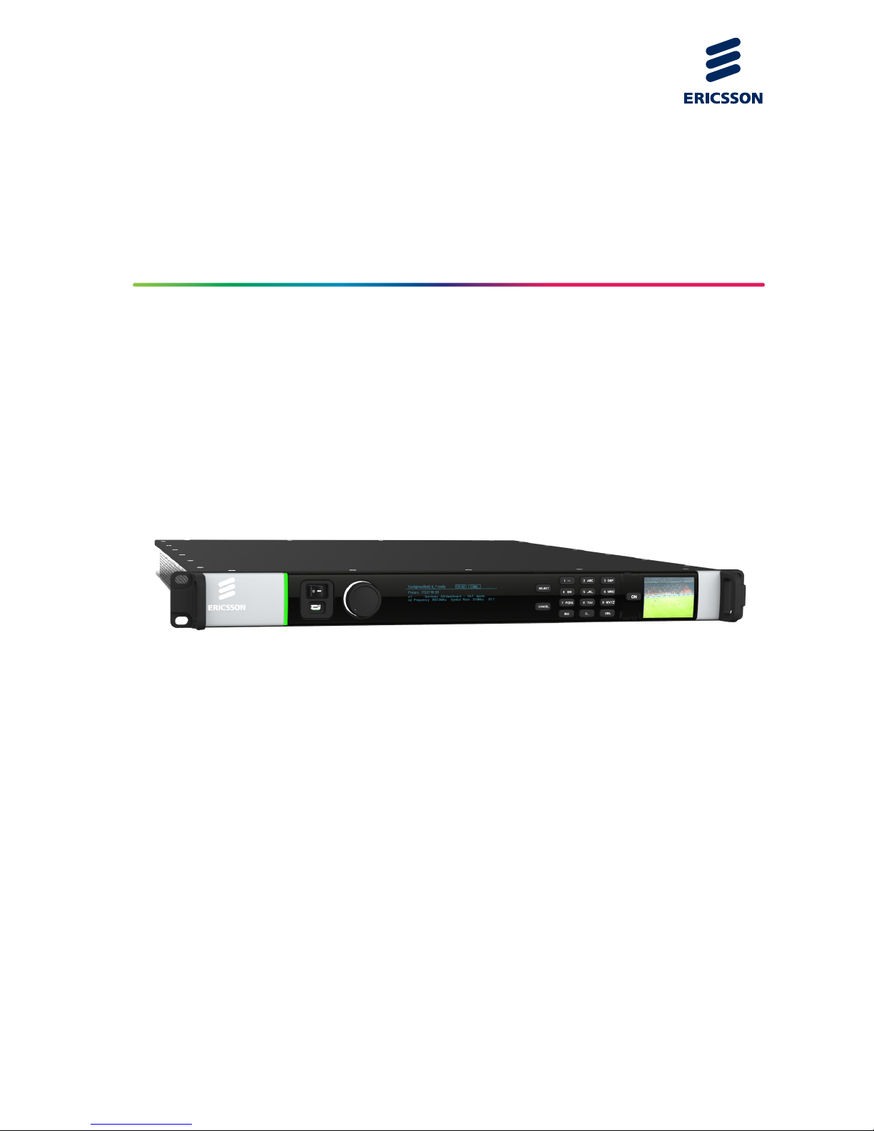
The AVP is a flexible platform consisting of a base unit or chassis into which various
option cards can be plugged. The base unit provides an Ethernet control interface,
Ethernet data interfaces, and basic Transport Stream processing functionality. Other
functionalities such as video encoding, audio encoding, and additional input or
output interfaces are provided by the addition of option cards.
The AVP is designed for flexibility, modularity, multi-codec capabilities, and multiple
independent outputs. Please ensure that you are familiar with the operation of the
unit by reading this guide carefully.
This Reference Guide should be kept in a safe place for reference for the life of the
equipment. It is not intended that this Reference Guide will be amended by the issue
of individual pages. Any revision will be by a complete reissue. Further copies of this
Reference Guide can be ordered from the address listed in Customer Services. If
passing the equipment to a third party, also pass the relevant documentation.
Revision History
Issues of this Reference Guide are listed below:
Issue Date
Software
Version
Comments
A May 2013 9.4.x Initial release of the AVP Family (AVP 4000)
Reference Guide Sv 9.4.x
B August 2013 9.5.x Updated to software version 9.5.x
New supported features added
C October 2013 9.6.x Updates for software version 9.6.x
New supported features added.
D January 2014 9.7.x Updates for software version 9.7.x
New supported features added.
E April 2014 9.8.x Updates for software version 9.8.x
New supported features added.
F August 2014 9.10.x Updates for software version 9.10.x
New supported features added.
G December 2014 9.11.x Updates for software version 9.11.x
New supported features added.

Preliminary Pages
1/1553-FGC 101 1790 Uen Y
v
Issue Date
Software
Version
Comments
H May 2015 9.13.x Updates for software version 9.12.x and
9.13.x. New supported features added.
J October 2015 9.16.x Updates for software version 9.16.x. New
supported features added.
K December 2015 9.17.x Updates for software version 9.17.x. New
supported features added.
L February 2016 9.18.x Updates for software version 9.18.x. New
supported features added.
M April 2016 9.19.x Updates for software version 9.19.x. New
supported features added.
N September 2016 9.22.x Updates for software versions 9.20.x, 9.21.x.
and 9.22.x New supported features added.
S November 2016 9.23.x Updates for software versions 9.23.x New
supported features added.
T December 2016 9.24.x Updates for software versions 9.24.x New
supported features added.
U March 2017 9.25.x Updates for software versions 9.25.x New
supported features added.
V April 2017 9.26.x Updates for software versions 9.26.x New
supported features added.
W June 2017 9.27.x Updates for software versions 9.27.x New
supported features added.
X September 2017 9.29.x Updates for software versions 9.28 and
9.29.x New supported features added.
Y January 2018 9.31.x Updates for software versions 9.31. New
supported features added.
Associated Documents
The following manuals/guides are also associated with this equipment:
Ericsson Document Identity Title
1/1553-FGB 101 752 Video Processing/Stream Processing
Products – Generic Product Information Quick Guide
174 02-FGB 101 348 Installation, Safety and Compliance
Information Generic Product Information Reference Guide

Preliminary Pages
vi
1/1553-FGC 101 1790 Uen Y
Useful Links:
Installation, Safety and Compliance Information – Generic Product Information Reference Guide can be viewed at:
http://archive.ericsson.net/service/internet/picov/get?DocNo=17402FGB101348&Lang=EN&HighestFree=Y
Product Guide downloads are available for all Product Families:
http://www.ericsson.com/ourportfolio/products/television-and-video
Trademarks
All best endeavors have been made to acknowledge registered trademarks and
trademarks used throughout this Reference Guide. Any notified omissions will be
rectified in the next issue of this Reference Guide. Some trademarks may be
registered in some jurisdictions but not in others.
Registered trademarks and trademarks used are acknowledged below and marked
with their respective symbols. However, they are not marked within the text of this
Reference Guide.
Registered Trademarks
Dolby
®
Registered trademark of Dolby Laboratories Licensing
Corporation.
GuideBuilder
®
Registered trademark of Triveni Digital Inc.
Trademarks
Reflex™ Trademark of Ericsson Television.
Patents
The feature “Phase Aligned Audio” is patented Ericsson functionality.
Warnings, Cautions and Notes
Heed Warnings
All warnings on the product and in the operating instructions should be adhered to.
The manufacturer can not be held responsible for injuries or damage where
warnings and cautions have been ignored or taken lightly.
Read Instructions
All the safety and operating instructions should be read before this product is
operated.

Preliminary Pages
1/1553-FGC 101 1790 Uen Y
vii
Follow Instructions
All operating and use instructions should be followed.
Retain Instructions
The safety and operating instructions should be retained for future reference.
Warning!
Warnings give information which, if strictly observed, will prevent personal injury or
death, or damage to property or the environment. They are highlighted for
emphasis, as in this example, and are placed immediately preceding the point at
which the reader requires them.
Caution!
Cautions give information which, if strictly followed, will prevent damage to
equipment or other goods. They are highlighted for emphasis, as in this example,
and are placed immediately preceding the point at which the reader requires them.
Note: Notes provide supplementary information. They are highlighted for
emphasis, as in this example, and are placed immediately after the relevant
text.
EMC Compliance
This equipment is certified to the EMC requirements detailed in the Installation,
Safety and Compliance Information for Ericsson Compression Products Reference
Guide supplied with your product. To maintain this certification, only use the leads
supplied or if in doubt contact Customer Services.
Contact Information
Support Services
Ericsson understands that our products are “mission-critical”, providing services that
influence customer perception and impact your revenue. Our objective is to ensure
that you realize maximum utility and achieve the highest levels of availability from
our products. To realize that objective, we offer a variety of Service Level
Agreements designed to meet your business needs and budget.

Preliminary Pages
viii
1/1553-FGC 101 1790 Uen Y
Warranty
All Ericsson products and systems are designed and built to the highest standards
and are covered under a comprehensive 12-month warranty.
Service Level Agreements
Customers may choose one of several Support packages, either as an
enhancement during the standard 12-month warranty or as an extension after the
warranty has expired.
For standalone equipment, customers may choose either Ericsson’s Extended
Hardware Warranty or Secure Basic Support. Extended Hardware Warranty
provides hardware repair of covered equipment after the expiration of the standard
warranty. Secure Basic Support provides hardware repair, remote diagnostics and
support, and 24x7x365 remote support for emergencies.
For systems, along with Secure Basic Support, customers have the option of either
Secure Advanced Support or Secure Superior Support. These support packages
provide higher committed response and resolution times, onsite support where
necessary, service performance review and a host of other proactive services to
help you get the maximum return on your investment in Ericsson solutions.
Call Ericsson Sales for more details.
Customer Services
Europe, Middle East
and Africa
Tel: +44 (0) 23 8048 4455
Fax: +44 (0) 23 8048 4467
Email: tvsupportemea@ericsson.com
Americas
Tel: +1 888 671 1268
Tel: +1 678 812 6255
Fax: +1 678 812 6263
Email: tvsupportamericas@ericsson.com
US and Canada
International
Asia
Tel: +852 2590 3820
Fax: +852 2590 9550
Email: tvsupportapac@ericsson.com
Hong Kong
Hong Kong
Australia and New
Zealand
Tel: +61 (0) 2 9111 4080
Fax: +61 (0) 2 9111 4949
Email: tvsupportanz@ericsson.com
Internet Address
www.ericsson.com
Technical Training
Ericsson provides a wide range of training courses on the operation and
maintenance of our products and on their supporting technologies. Ericsson can
provide both regularly scheduled courses and training tailored to individual needs.
Courses can be run either at your premises or at one of our dedicated training
facilities.

Preliminary Pages
1/1553-FGC 101 1790 Uen Y
ix
International
Tel: +44 (0) 23 8048 4229
Fax: +44 (0) 23 8048 4161
Email: tvglobaltraining@ericsson.com
Customer Services and Technical Training Postal Address
Ericsson
Unit 2
Strategic Park
Comines Way
Hedge End
Southampton
Hampshire
SO30 4DA
United Kingdom
Return of Equipment
If you need to return equipment for repair please contact your local Ericsson
Customer Services Department.
Please refer to the Customer Services Contact Information on Page viii.
You will then be directed to return the faulty equipment to a repair centre with
the appropriate facilities for that equipment. A tracking number will be issued that
should be used if you need to enquire about the progress of the repair. The
equipment should be properly packed and the tracking number should be clearly
marked on the outside of the packaging
.
Technical Publications
If you need to contact Ericsson Technical Publications regarding this publication,
e-mail:
tvtechpubs@ericsson.com.

Preliminary Pages
x
1/1553-FGC 101 1790 Uen Y
BLANK

1/1553-FGC 101 1790 Uen Y
1-1
1 Introduction
Chapter 1
Contents
1.1 Introduction ......................................................................................... 1-3
1.1.1 Who Should Use this Reference Guide ............................................... 1-3
1.1.2 Software Version ................................................................................. 1-3
1.1.3 New Features in this Release .............................................................. 1-3
1.1.4 What Equipment is Covered by this Reference Guide ......................... 1-4
1.1.4.1 AVP 4000 Chassis Options ................................................................. 1-4
1.1.4.2 AVP 4000 Software Value Packs ......................................................... 1-4
1.1.4.3 AVP 4000 Field Upgrade Software Value Packs ................................. 1-7
1.1.4.4 AVP 4000 Option Cards .................................................................... 1-10
1.1.4.5 AVP 4000 Field Upgrade Option Cards ............................................. 1-10
1.2 AVP 4000 Overview .......................................................................... 1-11
1.3 Front Panel ........................................................................................ 1-12
1.3.1 Power Switch ..................................................................................... 1-12
1.3.2 Confidence Monitor ........................................................................... 1-12
1.3.3 Light Bar ............................................................................................ 1-12
1.3.4 USB Connector ................................................................................. 1-13
1.3.5 Rotary Knob ...................................................................................... 1-13
1.3.6 Main Display ...................................................................................... 1-13
1.3.7 Keypad .............................................................................................. 1-13
1.4 Base Chassis Options ....................................................................... 1-13
1.4.1 AVP4000/BAS/1AC 1RU and AVP4000/BAS/1AC/ED Base
Chassis ............................................................................................. 1-13
1.4.2 AVP4000/BAS/2AC 1RU Base Chassis ............................................. 1-14
1.4.3 AVP4000/BAS/2ACFL 1RU Base Chassis ........................................
1-14
1.4.
4 AVP4000/BAS/1DC and AVP4000/BAS/2DC 1RU Base Chassis ...... 1-14
1.5 License Keys ..................................................................................... 1-15
List of Figures
Figure 1.1 Front Panel ........................................................................................ 1-12
Figure 1.2 Confidence Monitor ........................................................................... 1-12
Figure 1.3 AVP4000/BAS/1AC Rear Panel with No Cards Fitted ........................ 1-13
Figure 1.4 AVP4000/BAS/2AC Rear Panel with No Cards Fitted ........................ 1-14
Figure 1.5 AVP4000/BAS/2ACFL Rear Panel .................................................... 1-14
Figure 1.6 AVP4000/BAS/1DC and AVP4000/BAS/2DC Rear Panel with No
Cards Fitted ....................................................................................... 1-14

Introduction
1-2
1/1553-FGC 101 1790 Uen Y
List of Tables
Table 1.1 AVP 4000 Base Chassis Options ........................................................ 1-4
Table 1.2 AVP 4000 Value Packs Purchased with Chassis ................................ 1-5
Table 1.3 AVP 4000 Value Pack Upgrade Options ............................................. 1-7
Table 1.4 AVP 4000 Option Cards .................................................................... 1-10
Table 1.5 AVP 4000 Field Upgrade Option Cards ............................................. 1-11

Introduction
1/1553-FGC 101 1790 Uen Y
1-3
1.1 Introduction
1.1.1 Who Should Use this Reference Guide
This Reference Guide is written for operators / users of the Advanced Video
Processor (AVP) 4000. It describes the unit’s functions and operation. The
Reference Guide is written to assist in the installation and day-to-day operation and
care of the unit. Maintenance information requiring the covers to be removed is not
included.
Warning!
Do not remove the top cover of this equipment. Hazardous voltages are present
within this equipment and may be exposed if the top cover is removed. Only
Ericsson television trained and approved service engineers are permitted to service
this equipment.
Caution!
Unauthorized maintenance or the use of non-approved replacements may affect the
equipment specification and invalidate any warranties.
1.1.2 Software Version
This Reference Guide covers the functions of software versions 9.31 and later.
To verify the installed version either:
• Access the front panel, see Chapter 4, Front Panel Control.
• Access the Web Browser screens, see Chapter 5, Web GUI Control.
This manual continues to be relevant to subsequent build versions where the
functionality of the equipment has not changed. Where the build standard changes
the functionality, a new issue of this manual will be provided. The appropriate
number should be quoted in all correspondence with Ericsson.
1.1.3 New Features in this Release
The 9.31 release of software supports the following features:
• Four-slice encoding in HEVC UHD 4K.
• Automatic switching to CALVC for bitrates above 50 Mbps, for HEVC encoding.
• MGP support on systems using different subnet outputs.

Introduction
1-4
1/1553-FGC 101 1790 Uen Y
• SD or HD automatic input detection when encoding to SD.
• Improvements in Reflex.
1.1.4 What Equipment is Covered by this Reference Guide
This Reference Guide covers the AVP 4000 main units and options.
1.1.4.1 AVP 4000 Chassis Options
The base chassis options available for the AVP 4000 are described in the following
table.
Table 1.1 AVP 4000 Base Chassis Options
Marketing Code Price Object Number Supply Object Number Description
AVP4000/BAS/1AC/A FAZ 101 0196/185 KDU 137 935/7 AVP 4000 Single AC PSU Chassis
AVP4000/BAS/2AC/A FAZ 101 0196/186 KDU 137 935/8
AVP 4000 Dual AC PSU Chassis (4
option slots)
AVP4000/BAS/2ACFL/A FAZ 101 0196/187 KDU 137 935/9
AVP 4000 Dual AC PSU with Flying
Leads Chassis
AVP4000/BAS/1DC/A FAZ 101 0196/188 KDU 137 935/10 AVP 4000 Single DC PSU Chassis
AVP4000/BAS/2DC/A FAZ 101 0196/189 KDU 137 935/11 AVP 4000 Dual DC PSU Chassis
AVP4000/BAS/1AC/ED/A FAZ 101 0196/190 KDU 137 935/12
AVP 4000 Single AC PSU with
enhanced density. Ambient
temperature restrictions apply.
The AVP 4000 base chassis offers the capabilities:
• Remux
• BISS encryption
• PROFEC (SMPTE 2022-1) on output
• Pass-thru of audio
1.1.4.2 AVP 4000 Software Value Packs
The functionality of the AVP 4000 can be augmented by purchasing software value
packs, as listed in the following table.

Introduction
1/1553-FGC 101 1790 Uen Y
1-5
Table 1.2 AVP 4000 Value Packs Purchased with Chassis
Marketing Code Price Object Number Supply Object Number Description
AVP/SWO/VP/SD FAZ 101 0196/191 FAT 102 3694
Standard Definition value pack
offering:
• MPEG-2 encode
• MPEG-4 encode
• Transcode
• Reflex
• DPI
• PSIP table download
• Teletext to DVB sub
• Loudness control on 2 pairs
• MPEG-1 Layer II audio
AVP/SWO/VP/HD FAZ 101 0196/192 FAT 102 3695 High Definition value pack offering:
• MPEG-2 encode HD + SD
• MPEG-4 encode HD + SD
• Transcode
• Reflex
• DPI
• PSIP table download
• Teletext to DVB sub
• Loudness control on 4 pairs
• MPEG-1 Layer II audio
AVP/SWO/VP/ABR/HD FAZ 101 0196/193 FAT 102 3696 ABR value pack offering:
• MPEG-4 ABR encoding HD + SD
• Transcode
• 4:2:2 10 bit (Decode and Encode)
• DPI
• 4 pairs AAC encode with Loudness
control
AVP/SWO/VP/CONT FAZ 101 0196/194 FAT 102 3697 Contribution value pack offering:
• 4:2:2 10 bit Encode
AVP/SWO/VP/CONT/AUDIO FAZ 101 0196/195 FAT 102 3698
Audio for Contribution value pack
offering:
• Phase Aligned Audio (6 ch)
AVP/SWO/VP/M1L2 FAZ 101 0196/201 FAT 102 3704 Audio value pack for
• MPEG-1 Layer II encode of up to 2
channels of audio (e.g. stereo).
• Loudness control of the 2
channels.
AVP/SWO/VP/AAC FAZ 101 0196/196 FAT 102 3699 Audio value pack for:
• AAC-LC or HE-AAC encode of up
to 2 channels of audio (e.g. stereo).
• Loudness control of the 2
channels.
Note 3 packs required for surround
encoding.
AVP/SWO/VP/DOLBY/AC3 FAZ 101 0196/198 FAT 102 3701 Audio value pack for:
• Dolby Digital encode of up to 2
channels of audio (e.g. stereo).
• Loudness control of the 2
channels.
Note 3 packs required for surround
encoding.

Introduction
1-6
1/1553-FGC 101 1790 Uen Y
Marketing Code Price Object Number Supply Object Number Description
AVP/SWO/VP/DOLBY/PLUS FAZ 101 0196/200 FAT 102 3703 Audio value pack for:
• Dolby Digital Plus encode of up to
2 channels of audio (e.g. stereo).
• Loudness control of the 2
channels.
Note 3 packs required for surround
encoding.
AVP/SWO/VP/DOLBY/AC3/DEC FAZ 101 0196/199 FAT 102 3702 Audio value pack for:
• Decode of one compressed stream
of Dolby Digital
AVP/SWO/VP/DOLBYE/DEC FAZ 101 0196/197 FAT 102 3700 Audio value pack for:
• Decode of one compressed stream
of Dolby E
CE/SWO/VP/HEVC/HEVC/HD FAZ 101 0196/278 FAT 102 3822
High Definition HEVC value pack
offering:
• 1 channel of HD HEVC
• 4 channels of MPEG-1 Layer II
audio encode
CE/SWO/VP/HEVC/HEVC/4K FAZ 101 0196/279 FAT 102 3823
Ultra High Definition HEVC value pack
offering:
• UHD HEVC
• 16 channels of MPEG-1 Layer II
audio encode
CE/SWO/VP/HEVC/MP4/HD FAZ 101 0196/304 FAT 102 3945
High Definition H264 value pack
offering:
• 1 channel of HD H264
• 4 channels of MPEG-1 Layer II
audio encode
CE/SWO/VP/HEVC/MP4/X4 Contribution value pack offering:
• 4 channels of 4:2:2 encode for HD
video
CE/SWO/VP/HEVC/CONT FAZ 101 0196/280 FAT 102 3824 Contribution value pack offering:
• 1 channel of 4:2:2 encode for HD
video
CE/SWO/VP/HEVC/CONT/X4 FAZ 101 0196/281 FAT 102 3825 Contribution value pack offering:
• 4 channels of 4:2:2 encode for HD
video
CE/SWO/CE-HEVC/SLD FAZ 101 0196/295 FAT 102 3889
Ultra High Definition HEVC value pack
offering:
Enables 1 UHD HD channel for Super
Low Delay
CE/SWO/CE-HEVC/SLD/4K FAZ 101 0196/296 FAT 102 3890
Ultra High Definition HEVC value pack
offering:
Enables 1 UHD 4k channel for Super
Low Delay
CE/SWO/VP/CONT/AUDIO FAZ 101/0196/254 FAT 102 3784 Contribution audio value pack offering:
• Additional 4 channels of MPEG-1
Layer II encode
• Phase Aligned Audio (6 channel)

Introduction
1/1553-FGC 101 1790 Uen Y
1-7
Marketing Code Price Object Number Supply Object Number Description
CE/SWO/VP/CONT/AUDIO/X4 FAZ 101/0196/282 FAT 102 3826 Contribution audio value pack offering:
Additional 8 channels of MPEG-1
Layer II encode
• 4 x Phase Aligned Audio (6
channel)
CE/SWO/VP/AAC FAZ 101/0196/256 FAT 102 3786 Audio value pack for:
• AAC-LC or HE-AAC encode of up
to 2 channels of audio (e.g. stereo).
Note 3 packs required for surround
encoding.
CE/SWO/VP/DOLBY/AC3 FAZ 101/0196/257 FAT 102 3787 Audio value pack for:
• Dolby Digital encode of up to 2
channels of audio (e.g. stereo).
Note 3 packs required for surround
encoding.
CE/SWO/VO/M1L2 FAZ 101/0196/255 FAT 102 3785 Audio value pack for:
• MPEG-1 Layer II encode of up to 2
channels of audio (e.g. stereo).
AVP/SWO/VP/JUNG FAZ 101 0196/315 FAT 102 3998 Audio value pack for:
• Junger LevelMagic control for
Taiwanese NCC compliance.
1.1.4.3 AVP 4000 Field Upgrade Software Value Packs
Further value packs may be added to the AVP 4000 after the equipment has been
shipped via the field upgradable options as listed below.
Table 1.3 AVP 4000 Value Pack Upgrade Options
Marketing Code Price Object Number Supply Object Number Description
AVP/UPS/VP/SD FAZ 101 0196/202 FAT 102 3705
Standard Definition value pack
offering:
• MPEG-2 encode
• MPEG-4 encode
• Transcode
• Reflex
• DPI
• PSIP table download
• Teletext to DVB sub
• Loudness control on 2 pairs
• MPEG-1 Layer II audio
AVP/UPS/VP/HD FAZ 101 0196/203 FAT 102 3706 High Definition value pack offering:
• MPEG-2 encode HD + SD
• MPEG-4 encode HD + SD
• Transcode
• Reflex
• DPI
• PSIP table download
• Teletext to DVB sub
• Loudness control on 4 pairs
• MPEG-1 Layer II audio

Introduction
1-8
1/1553-FGC 101 1790 Uen Y
Marketing Code Price Object Number Supply Object Number Description
AVP/UPS/VP/ABR/HD FAZ 101 0196/204 FAT 102 3707 ABR value pack offering:
• MPEG-4 ABR encoding HD + SD
• Transcode
• 4:2:2 10 bit (Decode and Encode)
• DPI
• 4 pairs AAC encode with Loudness
control
AVP/UPS/VP/CONT FAZ 101 0196/205 FAT 102 3708 Contribution value pack offering:
• 4:2:2 10 bit Encode
AVP/UPS/VP/CONT/AUDIO FAZ 101 0196/206 FAT 102 3709
Audio for Contribution value pack
offering:
• Phase Aligned Audio (6 ch)
AVP/UPS/VP/M1L2 FAZ 101 0196/212 FAT 102 3715 Audio value pack for:
• MPEG-1 Layer II encode of up to 2
channels of audio (e.g. stereo).
• Loudness control of the 2
channels.
AVP/UPS/VP/AAC FAZ 101 0196/207 FAT 102 3710 Audio value pack for:
• AAC-LC or HE-AAC encode of up
to 2 channels of audio (e.g. stereo).
• Loudness control of the 2
channels.
Note 3 packs required for surround
encoding.
AVP/UPS/VP/DOLBY/AC3 FAZ 101 0196/209 FAT 102 3712 Audio value pack for:
• Dolby Digital encode of up to 2
channels of audio (e.g. stereo).
• Loudness control of the 2
channels.
Note 3 packs required for surround
encoding.
AVP/UPS/VP/DOLBY/PLUS FAZ 101 0196/211 FAT 102 3714 Audio value pack for:
• Dolby Digital Plus encode of up to
2 channels of audio (e.g. stereo).
• Loudness control of the 2
channels.
Note 3 packs required for surround
encoding.
AVP/UPS/VP/DOLBY/AC3/DEC FAZ 101 0196/210 FAT 102 3713 Audio value pack for:
• Decode of one compressed stream
of Dolby Digital
AVP/UPS/VP/DOLBYE/DEC FAZ 101 0196/208 FAT 102 3711 Audio value pack for:
• Decode of one compressed stream
of Dolby E
CE/UPS/VP/HEVC/HEVC/HD FAZ 101 0196/283 FAT 102 3827
High Definition HEVC value pack
offering:
HD HEVC
4 Channels of MPEG-1 Layer II audio
encode

Introduction
1/1553-FGC 101 1790 Uen Y
1-9
Marketing Code Price Object Number Supply Object Number Description
CE/UPS/VP/HEVC/HEVC/4K
FAZ 101 0196/284 FAT 102 3828
Ultra High Definition HEVC value pack
offering:
UHD HEVC
16 channels of MPEG-1 Layer II audio
encode
CE/UPS/VP/HEVC/MP4/HD FAZ 101 0196/306 FAT 102 3947
High definition MPEG-4 value pack
offering:
HD MPEG-4 AVC
4 channels of MPEG-1 Layer II audio
encode
CE/UPS/VP/HEVC/MP4/X4
High definition MPEG-4 value pack
offering:
4 channels HD MPEG-4 AVC
16 channels of MPEG-1 Layer II audio
encode
CE/UPS/VP/HEVC/CONT FAZ 101 0196/285 FAT 102 3829 Contribution value pack offering:
• 1 channel of 4:2:2 encode for HD
video
CE/UPS/VP/HEVC/CONT/X4 FAZ 101 0196/286 FAT 102 3830 Contribution value pack offering:
• 4 channels of 4:2:2 encode for HD
video
CE/UPS/VP/HEVC/SLD FAZ 101 0196/297 FAT 102 3891
Ultra High Definition HEVC value pack
offering:
Enables 1 UHD HD channel for Super
Low Delay
CE/UPS/VP/HEVC/SLD/4K FAZ 101 0196/298 FAT 102 3892
Ultra High Definition HEVC value pack
offering:
Enables 1 UHD 4k channel for Super
Low Delay
CE/UPS/CE-HEVC/SLD/
HDTO4K
FAZ 101 0196/299 FAT 102 3993
Upgrade to Super Low Delay from HD
to 4K UHD encode.
Note must already have SLD license.
CE/UPS/VP/HEVC/CONT/X3 FAZ 101 0196/300 FAT 102 3894
HEVC 422 upgrade value pack
offering:
Upgrade from single 4:2:2 encode to
support 4:2:2 UHD encode.
CE/UPS/VP/HEVC/HEVC/X3 FAZ 101 0196/301 FAT 102 3895
HEVC HD to UHD upgrade value pack
offering:
UHD HEVC encode to existing HD
HEVC encode.
CE/UPS/VP/CONT/AUDIO FAZ 101 0196/260 FAT 102 3790 Contribution audio value pack offering:
• Additional 4 channels of MPEG-1
Layer II encode
• Phase Aligned Audio (6 channel)
CE/UPS/VP/CONT/AUDIO/X4 FAZ 101 0196/287 FAT 102 2831 Contribution audio value pack offering:
Additional 8 channels of MPEG-1
Layer II encode
• 4 x Phase Aligned Audio (6
channel)

Introduction
1-10
1/1553-FGC 101 1790 Uen Y
Marketing Code Price Object Number Supply Object Number Description
CE/UPS/VP/CONT/AUDIO/X3 FAZ 101 0196/302 FAT 102 3896 Contribution audio value pack offering:
Additional 6 channels of MPEG-1
LayerII encode
• 4 x Phase Aligned Audio (6
channel)
CE/UPS/VP/AAC FAZ 101 0196/262 FAT 102 3791 Audio value pack for:
• AAC-LC or HE-AAC encode of up
to 2 channels of audio (e.g. stereo).
Note 3 packs required for surround
encoding.
CE/UPS/VP/DOLBY/AC3 FAZ 101 0196/263 FAT 102 3793 Audio value pack for:
• Dolby Digital encode of up to 2
channels of audio (e.g. stereo).
Note 3 packs required for surround
encoding.
CE/UPS/VP/M1L2 FAZ 101 0196/261 FAT 102 3791 Audio value pack for:
• MPEG-1 Layer II encode of up to 2
channels of audio (e.g. stereo).
AVP/UPS/VP/JUNG FAZ 101 0196/316 FAT 102 3999 Audio value pack for:
• Junger LevelMagic control for
Taiwanese NCC compliance.
1.1.4.4 AVP 4000 Option Cards
The option cards available to purchase with the base chassis are shown in the
following table.
Table 1.4 AVP 4000 Option Cards
Marketing Code Price Object Number Supply Object Number Description
AVP/HWO/EI9001/A FAZ 101 0196/213 ROA 128 6446 Single channel EI9001 Encoder
AVP/HWO/EI9001T/A FAZ 101 0196/214 ROA 128 6447 Single channel EI9001 Transcoder
AVP/HWO/ASI/IO/A FAZ 101 0196/215 ROA 128 6448
ASI Input/Output Card with 2x Inputs
and 2x Outputs
AVP/HWO/EXTSYNC/A FAZ 101 0196/216 ROA 128 6449 External Sync Module
AVP/HWO/GPI/A FAZ 101 0196/217 ROA 128 6450 General Purpose Input Card
CE/HWO/HEVC/BNC/A FAZ 101 0196/272 ROA 128 6526
HEVC Media Processing module with
BNC connections
CE/HWO/HEVC/SFP/C/A FAZ 101 0196/273 ROA 128 6527 HEVC Card-SFP Copper
CE/HWO/HEVC/SFP/F/A FAZ 101 0196/274 ROA 128 6528 HEVC Card-SFP Fiber
1.1.4.5 AVP 4000 Field Upgrade Option Cards
Option cards may be added to an AVP 4000 as a field upgrade and are shown in the
following table.

Introduction
1/1553-FGC 101 1790 Uen Y
1-11
Table 1.5 AVP 4000 Field Upgrade Option Cards
Marketing Code Price Object Number Supply Object Number Description
AVP/UPH/EI9001/A FAZ 101 0196/218 ROA 128 6451 Single channel EI9001 Encoder
AVP/UPH/EI9001T/A FAZ 101 0196/219 ROA 128 6452 Single channel EI9001 Transcoder
AVP/UPH/ASI/IO/A FAZ 101 0196/220 ROA 128 6453
ASI Input/Output Card with 2x Inputs
and 2x Outputs
AVP/UPH/EXTSYNC/A FAZ 101 0196/221 ROA 128 6454 External Sync Module
AVP/UPH/GPI/A FAZ 101 0196/222 ROA 128 6455 General Purpose Input Card
CE/UPH/HEVC/BNC/A FAZ 101 0196/275 ROA 128 6530
HEVC Media Processing module
with BNC connections
CE/UPH/HEVC/SFP/C/A FAZ 101 0196/276 ROA 128 6531 HEVC Card-SFP Copper
CE/UPH/HEVC/SFP/F/A FAZ 101 0196/277 ROA 128 6532 HEVC Card-SFP Fiber
1.2 AVP 4000 Overview
The AVP 4000 is a flexible platform consisting of a base unit or chassis in to which
various option cards can be plugged. The base unit provides an Ethernet control
interface for configuration, an Ethernet data interfaces for data routing between the
host and the option cards, and basic Transport Stream processing functionality.
Other functionalities such as video encoding, audio encoding, or other input or
output interfaces are provided by option cards through various interfaces.
The following is a summary of the features of the base chassis:
• 19” 1 ‘RU’ rack mount chassis.
• Front panel main display and keypad for control and status reporting.
• Power switch.
• Tri-color light bar to indicate chassis health.
• Dual redundant Ethernet control ports.
• Dual redundant Ethernet ports for data input and output.
• Option card slots (the number of option cards that may be fitted is different for
each base unit)
• Option cards are ‘hot swappable’.
• Confidence monitor for monitoring input video stream.
Introduction
1-12
1/1553-FGC 101 1790 Uen Y
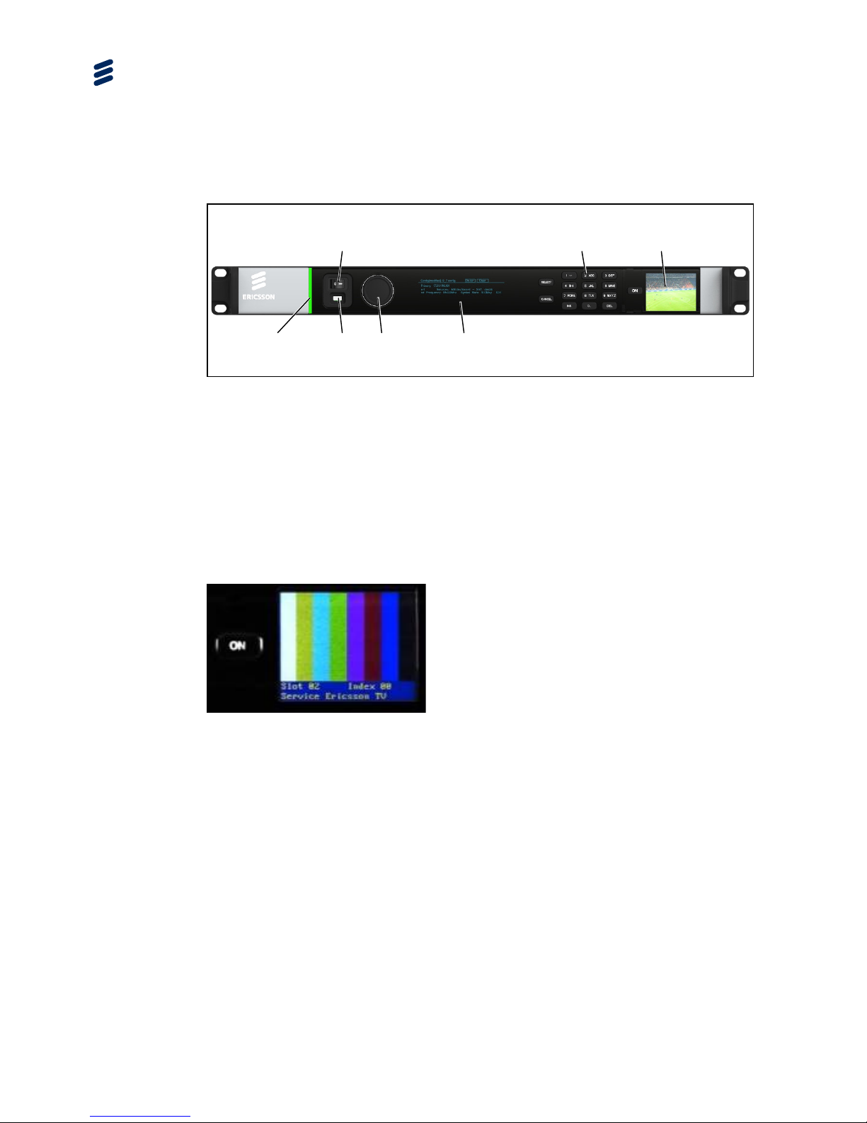
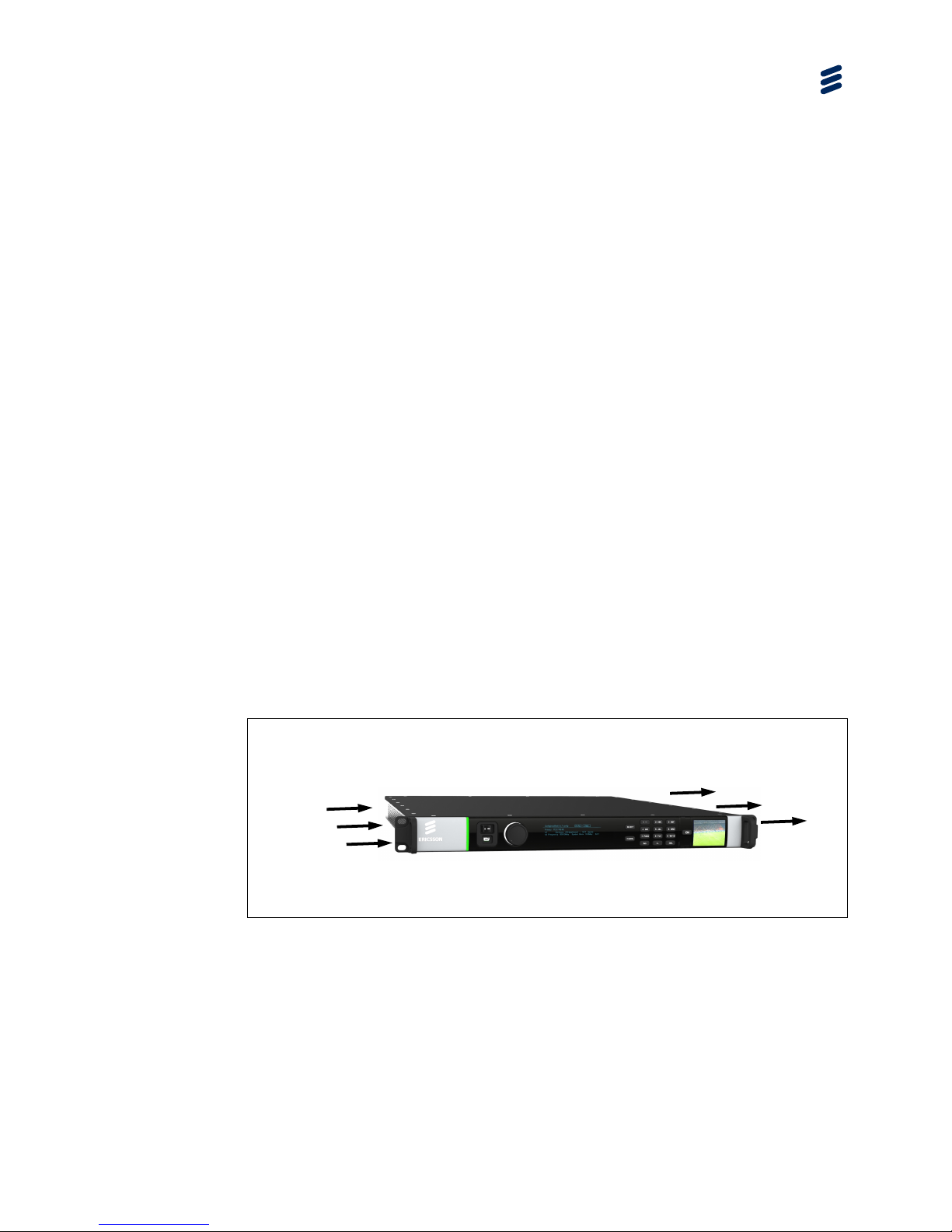
1.3 Front Panel
The front panel of the unit consists of a power switch, a confidence monitor, a light
bar, an USB Connector, a rotary knob, a main display and a keypad.
Figure 1.1 Front Panel
1.3.1 Power Switch
The mains switch is recessed to prevent accidental switch-off.
1.3.2 Confidence Monitor
The confidence monitor allows the user to monitor the selected input video signal.
Figure 1.2 Confidence Monitor
The confidence monitor is a 1.8 inch TFT LCD. The On key on the confidence
monitor turns the monitor on or off. By pressing and holding the On key, operation
related data is shown. The first line displays the total number of hours the monitor
has been operating; the second line displays the software version. The source of the
video to be displayed, the sleep timeout time and the monitor brightness can be
setup through the front panel or the web user interface. For details on how to
configure the settings for the confidence monitor see Chapter 3, Getting Started.
1.3.3 Light Bar
The light bar is green when there are no active alarms or warnings, and red if there
is a critical alarm. It is yellow if there is an active warning, minor or major alarm.
Power Switch
Light Bar
Mini USB
Rotary Knob
Main Display
Keypad
Confidence Monitor
Introduction
1/1553-FGC 101 1790 Uen Y
1-13
1.3.4 USB Connector
The USB connector provides an interface for saving or exporting configurations to,
and loading or importing configuration from an USB stick. Moreover, by applying an
USB-Ethernet adaptor, the Ethernet port of a control computer can be connected to
the USB connector on the Front Panel of the unit.
1.3.5 Rotary Knob
The rotary knob is used for scrolling through and selecting the menu items.
1.3.6 Main Display
Control and status information is displayed on a graphic VFD display.
1.3.7 Keypad
Select and Cancel keys, as well as a numeric keypad is provided for interaction.
1.4 Base Chassis Options
The AVP 4000 consists of a base chassis, AC or DC power supply inputs and up to
six option cards. The base chassis is a 1RU 19” rack mount chassis that contains
control interfaces and two pairs of dual redundant Ethernet ports for data output.
Option cards are responsible for video, audio and data processing, and for
producing output through various interfaces. The option cards are ‘Hot Swappable’,
that is, they can be inserted or removed while the chassis is powered on.
There are four base chassis options available:
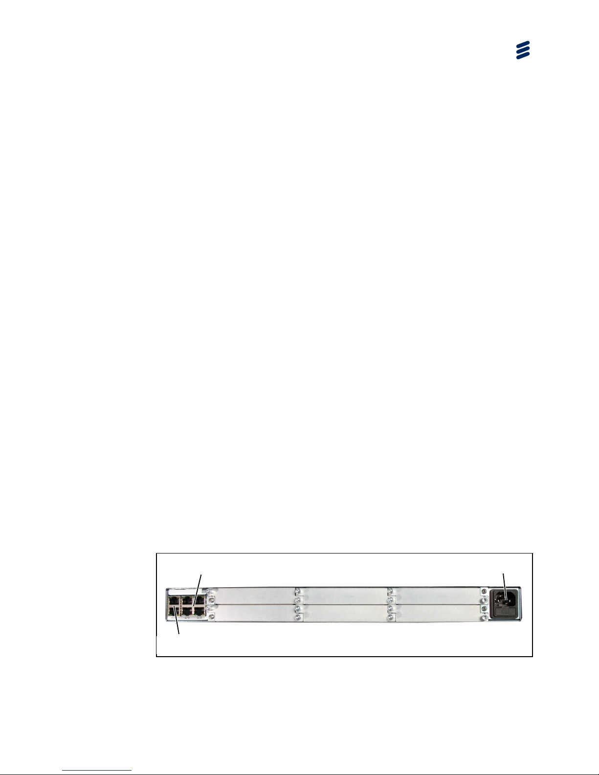
1.4.1 AVP4000/BAS/1AC 1RU and AVP4000/BAS/1AC/ED Base Chassis
These chassis options provide a single AC mains input and slots for up to six option
cards.
Figure 1.3 AVP4000/BAS/1AC Rear Panel with No Cards Fitted
Slot 2
Slot 4
Slot 6
Slot 1
Slot 3
Slot 5
Data Ethernet x4
Control Ethernet x2
AC Input
Introduction
1-14
1/1553-FGC 101 1790 Uen Y
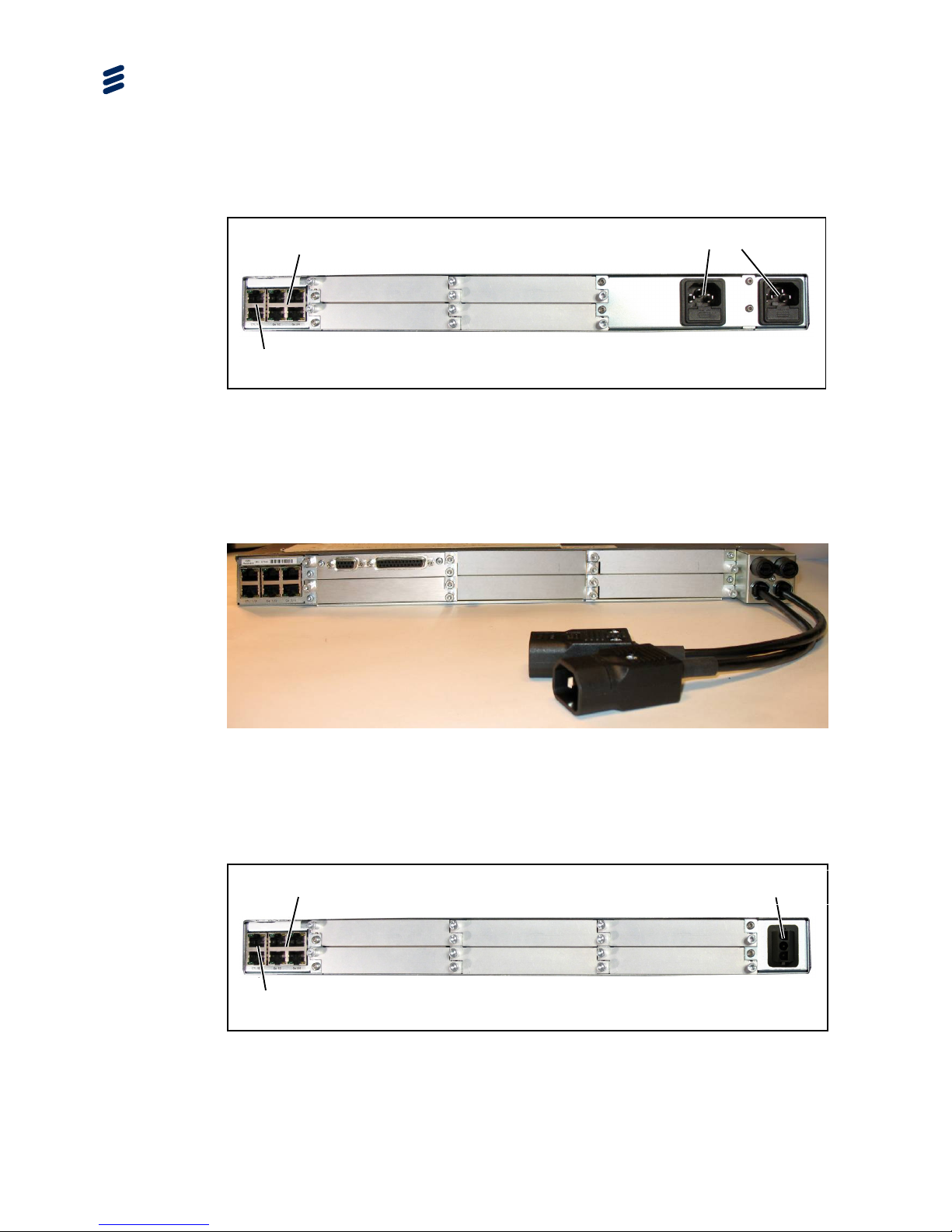
1.4.2 AVP4000/BAS/2AC 1RU Base Chassis
This chassis option provides a dual AC mains input and slots for up to four option
cards.
Figure 1.4 AVP4000/BAS/2AC Rear Panel with No Cards Fitted
1.4.3 AVP4000/BAS/2ACFL 1RU Base Chassis
This chassis option provides dual AC mains input via flying leads and slots for up to
six option cards.
Figure 1.5 AVP4000/BAS/2ACFL Rear Panel
1.4.4 AVP4000/BAS/1DC and AVP4000/BAS/2DC 1RU Base Chassis
These chassis options provide DC inputs and slots for up to six option cards.
Figure 1.6 AVP4000/BAS/1DC and AVP4000/BAS/2DC Rear Panel with No Cards
Fitted
Slot 2
Slot 4
Slot 1
Slot 3
Dual AC Inputs
Data Ethernet x4
Control Ethernet x2
Slot 2
Slot 4
Slot 6
Slot 1
Slot 3
Slot 5
Data Ethernet x4
Control Ethernet x2
DC Input

Introduction
1/1553-FGC 101 1790 Uen Y
1-15
1.5 License Keys
Licenses control the availability of some of the features accessible from the unit.
A License Key consists of a feature, and the number of instances of this feature that
are allowed within the chassis or option card.
License Keys are allocated on a ‘first configured first served’ basis within the
chassis. If an attempt is made to enable a feature, but the required license key is not
available then the feature is not enabled, and a log message is generated.
When a function that has a license associated with it is disabled, the license key is
released within 1 second, and thereafter available to be re-allocated.

Introduction
1-16
1/1553-FGC 101 1790 Uen Y
BLANK

1/1553-FGC 101 1790 Uen Y
2-1
2 Installing the Equipment
Chapter 2
Contents
2.1 Read This First! ................................................................................... 2-3
2.2 Mounting and Ventilation ..................................................................... 2-3
2.2.1 Fixing and Rack Mounting ................................................................... 2-3
2.2.2 Ventilation ........................................................................................... 2-3
2.3 Signal Connections.............................................................................. 2-4
2.3.1 Rear Panel Signal Connectors ............................................................ 2-4
2.3.2 Data Ethernet Connector ..................................................................... 2-4
2.3.3 Control Ethernet Connector ................................................................. 2-5
2.3.4 CE Option Modules ............................................................................. 2-6
2.3.4.1 Digital Video Input (CE-HEVC/BNC Option Module) ............................ 2-6
2.3.4.2 Digital Video Input (CE-HEVC/SFP Option Module) ............................ 2-7
2.3.5 ASI I/O Option Card Connectors.......................................................... 2-8
2.3.6 External Sync Input Option Card Connector ........................................ 2-8
2.3.7 GPI Option Card Connector ................................................................. 2-9
2.3.8 Mini USB Connector .......................................................................... 2-10
List of Figures
Figure 2.1 Air-Flow through the Equipment .......................................................... 2-3
Figure 2.2 ASI I/O Option Card ............................................................................. 2-8
Figure 2.3 External Sync Input Option Card ......................................................... 2-8
Figure 2.4 Mini USB Connector .......................................................................... 2-10
List of Tables
Table 2.1 Data Ethernet Connector ..................................................................... 2-4
Table 2.2 Link Speed: Left (Green) LED ............................................................. 2-5
Table 2.3 Link Activity: Right (Yellow) LED.......................................................... 2-5
Tabl
e 2.4 Control Ethernet Connector ................................................................. 2-5
Table 2.5 Port Status: Left (Green ) LED ............................................................. 2-6
Table 2.6 Link Activity: Right (Yellow ) LED ......................................................... 2-6
Table 2.7 Digital Video Input via the SDI Interface .............................................. 2-7
Table 2.8 Lock LED State Descriptions ............................................................... 2-7
Table 2.9 ASI I/O Option Card Connectors.......................................................... 2-8
Table 2.10 External Sync Input Option Card Connector ........................................ 2-8

Installing the Equipment
2-2
1/1553-FGC 101 1790 Uen Y
Table 2.11 GPI Data In Connector ........................................................................ 2-9
Table 2.12 GPI Alarm Contact Closure Connector ................................................ 2-9
Table 2.13 Data Input Connector Pin-out ............................................................ 2-10
Installing the Equipment
1/1553-FGC 101 1790 Uen Y
2-3
2.1 Read This First!
Please refer to the Installation, Safety and Compliance Information for Ericsson
Compression Products Reference Guide supplied with your product for full details of
installation requirements. This guide only contains additional product specific
information where required.
2.2 Mounting and Ventilation
2.2.1 Fixing and Rack Mounting
The equipment is designed for fixed use only and has been shipped with fixing
brackets suitable for a standard 19-inch rack. When installed in a rack, it should be
secured using the fixing brackets. In addition, support shelves must be used to
reduce the weight on the brackets. Ensure it is firmly and safely located and it has
an adequate free-flow of air.
Slide the unit onto the chassis supports and affix to the rack by means of an
M6 x 18 mm panhead screw in each corner.
A freestanding unit should be installed on a secure horizontal surface where it is
unlikely to be knocked or its connectors and leads disturbed.
2.2.2 Ventilation
Side openings in the unit, as well as side-mounted cooling fans, are provided for
ventilation. They ensure reliable operation of the product and protect it from
overheating. The openings of the fans must not be blocked or covered.
Figure 2.1 Air-Flow through the Equipment
Air is released
through vents at
the side of the unit.
Fans are
mounted on
this side of
the unit
Installing the Equipment
2-4
1/1553-FGC 101 1790 Uen Y
2.3 Signal Connections
2.3.1 Rear Panel Signal Connectors
Caution!
It is strongly recommended that the terminal marked at the rear panel of the
equipment is connected to a site Technical Earth before any external connections
are made and the equipment is powered. This limits the migration of stray charges.
Signal connections are made via the rear panel. The rear panels, which are
available are shown below. Full technical specifications for the connections are
given in Annex B.
Only the Data and Control Ethernet connectors and the PSU connectors are
mounted on the chassis. All other connections at the rear panel are provided with
the option modules that may be fitted.
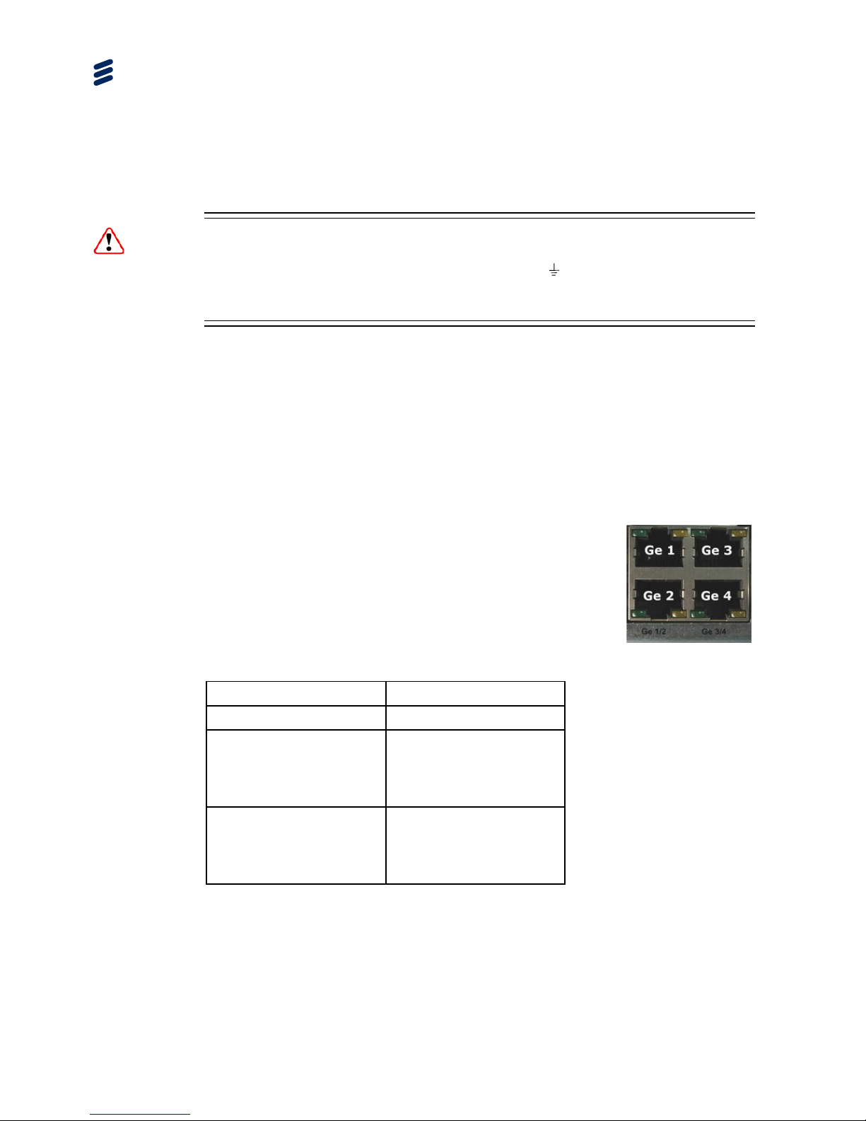
2.3.2 Data Ethernet Connector
The unit has four Ethernet ports - two for data input, and
two for data output and will respond to ARPs, pings and
other low-level Ethernet traffic. The ports are accessible
via RJ-45 connectors on the rear panel of the chassis.
These are labeled Ge 1, Ge 2, Ge 3 and Ge 4. Ge 1 and
Ge 2 are used for data input, while Ge 3 and Ge 4 are
data output.
Table 2.1 Data Ethernet Connector
Item Specification
Connector type RJ-45 (100/1000 Base T)
Connector designation Ge 1 (data input)
Ge 2 (data input)
Ge 3 (data output)
Ge 4 (data output)
Pin outs
(Unused pins are not connected)
Pin 1 - Tx Out (+)
Pin 2 - Tx Out (-)
Pin 3 - Rx In (+)
Pin 6 - Rx In (-)
Status and Activity Indication
Each Ethernet Data Port has a rear panel mounted status LED associated with it to
indicate link status, activity and speed as follows:
 Loading...