

Ericsson AVP 1000, AVP 2000, AVP 1000 1RU, AVP 3000, AVP 1000 Series Reference Manual
...
AVP Family (AVP 1000 (1RU), AVP 2000,
AVP 3000)
Software Version 9. 26.x
REFERENCE GUIDE
EN/LZT 790 0023/1 R16A

ii
EN/LZT 790 0023/1 R16A
LEIA O TEXTO ABAIXO ANTES DE MAIS NADA!
Preliminary Pages
ENGLISH (UK) - READ THIS FIRST!
If you do not understand the contents of this manual. DO NOT OPERATE
THIS EQUIPMENT. Also, translation into any EC official language of this
manual can be made available, at your cost.
ITALIANO - LEGGERE QUESTO AVVISO PER PRIMO!
Se non si capisce il contenuto del presente manuale. NON UTILIZZARE
L’APPARECCHIATURA.. È anche disponibile la versione italiana di questo
manuale, ma il costo è a carico dell’utente.
SVENSKA - LÄS DETTA FÖRST!
Om Ni inte förstår informationen i denna handbok. ARBETA DÅ INTE MED
DENNA UTRUSTNING. En översättning till detta språk av denna handbok
kan också anskaffas, på Er bekostnad.
PORTUGUÊS -
Se não compreende o texto deste manual. NÃO UTILIZE O
EQUIPAMENTO. O utilizador poderá também obter uma tradução do
manual para o português à própria custa.
FRANÇAIS - AVA NT TOUT, LIS EZ CE QUI S UIT!
Si vous ne comprenez pas les instructions contenues dans ce manuel. NE
FAITES PAS FONCTIONNER CET APPAREIL. En outre, nous pouvons
vous proposer, à vos frais, une version française de ce manuel.
DEUTSCH - LESEN SIE ZUERST DIESEN HINWEIS !
Sollte Ihnen der Inhalf dieses Handbuches nicht klar verständlich sein,
dann. BEDIENEN SIE DIESE GERÄTE NICHT! Eine Übersetzung des
Handbuches in diese Sprache ist gegen Berechnung lieferbar.
ESPAÑOL - LEA ESTE AVISO PRIMERO!
Si no entiende el contenido de este manual. NO OPERE ESTE EQUIPO.
Podemos asimismo suministrarle una traducción de este manual al (idioma)
previo pago de una cantidad adicional que deberá abon ar ust ed mis m o.
NEDERLANDS - LEES DIT EE RST!
Als u de inhoud van deze handleiding niet begrijpt. STEL DEZE
APPARATUUR DAN NIET IN WERKING. U kunt tevens, op eigen kosten,
Jos et ymmärrä käsikirjan sisältöä. ÄLÄ KÄYTÄ LAITETTA. Käsikirja
Udstyret må ikke betjenes. MEDMINDRE DE TIL FULDE FORSTÅR
INDHOLDET AF DENNE HÅNDBOG. Vi kan også for Deres regning levere
Αν δεν καταλάβετε το περιεχόμενο αυτού του βοηθήματος/εγχειριδίου. ΜΗΝ
ΛΕΙΤΟΥΡΓΗΣΕΤΕ ΑΥΤΟΝ ΤΟΝ ΕΞΟΠΛΙΣΜΟ. Επίσης, αυτό το εγχειρίδιο
είναι διαθέσιμο σε μετάφραση σε αυτή τη γλώσσα και μπορείτε να το
een vertaling van deze handleiding krijgen.
SUOMI - LUE ENNEN KÄYTTÖÄ!
voidaan myös suomentaa asiakkaan kustannuksella.
DANSK - LÆS DETTE FØRST!
en dansk oversættelse af den ne håndbog.
ΕΛΛΗΝΙΚΑ - ΔΙΑΒΑΣΤΕ ΠΡΩΤΑ ΑΥΤΟ!
αγοράσετε.
Copyright
© Copyright Ericsson AB 2017. All rights reserved. No part of this document may be reproduced in
any form without the written permission of the copyright owner.
Disclaimer
No part of this document may be reproduced in any form without the written permission of the
copyright owner.
The contents of this document are subject to revision without notice due to continued progress in
methodology, design and manufacturing. Ericsson shall have no liability for any error or damage of
any kind resulting from the use of this document.

Preliminary Pages
EN/LZT 790 0023/1 R16A
iii
Contents
Chapter 1: Introduction
This chapter identifies the equipment versions covered by this manual, describes
the purpose of the equipment in a typical system and lists the available options.
Chapter 2: Installing the Equipment
This chapter provides product specific installation information including rack
mounting, ventilation and pin-out details of the external connectors.
Chapter 3: Getting Started
This chapter provides a guide to powering up the unit, setting up the IP address and
using the unit.
Chapter 4: Front Panel Control
This chapter describes the front panel display menus and options and details any
operating procedures.
Chapter 5: Web GUI Control
This chapter describes the configuration of the unit using the Web Graphical User
Interface.
Chapter 6: Advanced Video Processing & Networking
This chapter describes the principles and techniques used in the design of the
equipment to aid in understanding its operation and function.
Chapter 7: Options, Licensing and Upgrades
This chapter provides details of option cards that may be fitted to this equipment.
Chapter 8: Preventive Maintenance and Fault-finding
This chapter details routine maintenance tasks, servicing advice and information
regarding warranty and maintenance. It also lists error and error messages that may
occur and recommends the action to be taken.
Annex A: Glossary
Annex B: Technical Specification
Annex C: Audio Coding Standards
Annex D: Differences for Contribution Encoder and Voyager II
Annex E: Alarms List
Annex F: Logo Creator

iv
EN/LZT 790 0023/1 R16A
Preliminary Pages
Introduction
The AVP is a flexible platform consisting of a base unit or chassis into which various
option cards can be plugged. The base unit provides an Ethernet control interface,
Ethernet data interfaces, and basic transport stream processing functionality. Other
functionalities such as video encoding, audio encoding, and additional input or
output interfaces are provided by the addition of option cards.
The AVP is designed for flexibility, modularity, multi-codec capabilities, and multiple
independent outputs. Please ensure that you are familiar with the operation of the
unit by reading this guide carefully.
This Reference Guide should be kept in a safe place for reference for the life of the
equipment. It is not intended that this Reference Guide will be amended by the issue
of individual pages. Any revision will be by a complete reissue. Further copies of this
Reference Guide can be ordered from the address listed in Customer Services. If
passing the equipment to a third party, also pass the relevant documentation.
The information in this Reference Guide also applies to the Contribution Encoder
and Voyager II products. Any differences are described in Annex D.
Revision History
Issues of this Reference Guide are listed below:
Issue Date
A Jan 2013 9.2.x Separate online help files combined for AVP 2000
B Apr 2013 9.4.x Updated to software version 9.4.x
C Jul 2013 9.5.x Updated to software version 9.5.x
D Nov 2013 9.6.x Updated for software version 9.6.x
E Jan 2014 9.7.x Updated for software version 9.7.x
Software
Version
Comments
(1553-FGC 101 1788 Uen B), AVP 3000 (1553FGC 101 1789 Uen B) and AVP 4100 (1553-FGC
101 1790 Uen B). Updated to software version 9.2.x
New supported features added
New supported features added
Included details of support for Contribution Encoder
and Voyager II
New supported features added
New supported features added
Section added to introduce Voyager GUI
F Apr 2014 9.8.x Updated for software version 9.8.x
AVP 4100 removed

Preliminary Pages
EN/LZT 790 0023/1 R16A
v
Issue Date
Software
Comments
Version
G Aug 2014 9.10.x Updated for software version 9.10.x.
Roll-off factors of 5, 10 and 15 percent supported
for DVB-S2.
H Dec 2014 9.11.x Updated for software version 9.11.x.
Adds support for DVB RF Carrier ID Voyager
II/AVP3000.
Adds option to include EIT and TDT tables in output
streams for ETR290 Level 3 compliance.
J May 2015 9.13.x Updated for software version 9.12.x and 9.13.x.
Adds AVP 1000 (1RU).
Adds support for DVB-S2X for
Voyager II/AVP3000.
K Aug 2015 9.15.x Updated for software version 9.15.
Support for Voyager Dashboard has been
superseded by the Simplified View, which extends
supported outputs to IP and ASI and is available for
AVP 2000 as well as AVP 3000.
Note: 9.15.x is the last software release to support
the Contribution Encoder and Voyager II products.
L Aug 2016 9.22.x Updated for software version 9.22.
Adds information for AVP1000 product.
Adds details of H.264 fixed latency buffer mode for
CE-x option cards.
BISS encryption per component within a service.
Adds details for CE-H EV C option module,
introduced in this release.
M Jan 2017 9.24.x Updated for software version 9.24.
Adds supports for support for closed captions and
timecode for CE-HEVC.
Adds support for loading a stored configuration
when a change of SDI input is detected to update
video and VBI configuration.
N Mar 2017 9.25.x Updated for software version 9.25.
Adds support for remote logging, CE-x and
HDR/WSS signaling for CE-HEVC.
S Apr 2017 9.26.x Updated for software version 9.26.
Adds support for SCTE-104 to SCTE-35 message
translation on HEVC Card, In-band Control via Data
Output ports, Generic ANC and Teletext on HEVC
Card.

vi
EN/LZT 790 0023/1 R16A
Preliminary Pages
Associated Docum ents
The following manuals/guides are also associated with this equipment:
Ericsson Document Identity Title
1/1424-EN/LZT 790 0038 Video Processing/Stream Processing
Products – Generic Product Information Quick Guide
1424-EN/LZT 790 0030 Installation, Safety and Compliance
Information Generic Product Information Reference Guide
Useful Links:
Installation, Safety and Compliance Information – Generic Product Information -
Reference Guide can be viewed at:
http://archive.ericsson.net/service/internet/picov/get?DocNo=17402FGB101348&Lang=EN&HighestFree=Y
Product Guide downloads are available for all Product Families:
http://www.ericsson.com/ourportfolio/products/television-and-video
Trademarks
All best endeavors have been made to acknowledge registered trademarks and
trademarks used throughout this Reference Guide. Any notified omissions will be
rectified in the next issue of this Reference Guide. Some trademarks may be
registered in some jurisdictions but not in others.
Registered trademarks and trademarks used are acknowledged below and marked
with their respective symbols. However, they are not marked within the text of this
Reference Guide.
Registered Trademarks
Dolby
GuideBuilder
Trademarks
Reflex™ Trademark of Ericsson Television.
®
Registered trademark of Dolby Laboratories.
®
Registered trademark of Triveni Digital Inc.
Patents
The feature “Phase Aligned Audio” is patented Ericsson functionality.

Preliminary Pages
EN/LZT 790 0023/1 R16A
vii
Warnings, Caut i ons and Notes
Heed Warnings
All warnings on the product and in the operating instructions should be adhered to.
The manufacturer can not be held responsible for injuries or damage where
warnings and cautions have been ignored or taken lightly.
Read Instructions
All the safety and operating instructions should be read before this product is
operated.
Follow Instructions
All operating and use instructions should be followed.
Retain Instructions
The safety and operating instructions should be retained for future reference.
Warning!
Warnings give information which, if strictly observed, will prevent personal injury or
death, or damage to property or the environment. They are highlighted for
emphasis, as in this example, and are placed immediately preceding the point at
which the reader requires them.
Caution!
Cautions give information which, if strictly followed, will prevent damage to
equipment or other goods. They are highlighted for emphasis, as in this example,
and are placed immediately preceding the point at which the reader requires them.
Note: Notes provide supplementary information. They are highlighted for
emphasis, as in this example, and are placed immediately after the relevant
text.
EMC Compliance
This equipment is certified to the EMC requirements detailed in the Installation,
Safety and Compliance Information for Ericsson Compression Products Reference
Guide supplied with your product. To maintain this certification, only use the leads
supplied or if in doubt contact Customer Services.

viii
EN/LZT 790 0023/1 R16A
Preliminary Pages
Contact Inform ation
Support Services
Ericsson understands that our products are “mission-critical”, providing services that
influence customer perception and impact your revenue. Our objective is to ensure
that you realize maximum utility and achieve the highest levels of availability from
our products. To realize that objective, we offer a variety of Service Level
Agreements designed to meet your business needs and budget.
Warranty
All Ericsson products and systems are designed and built to the highest standards
and are covered under a comprehensive 12-month warranty.
Service Level Agreements
Customers may choose one of several Support packages, either as an
enhancement during the standard 12-month warranty or as an extension after the
warranty has expired.
For standalone equipment, customers may choose either Ericsson’s Extended
Hardware Warranty or Secure Basic Support. Extended Hardware Warranty
provides hardware repair of covered equipment after the expiration of the standard
warranty. Secure Basic Support provides hardware repair, remote diagnostics and
support, and 24x7x365 remote support for emergencies.
For systems, along with Secure Basic Support, customers have the option of either
Secure Advanced Support or Secure Superior Support. These support packages
provide higher committed response and resolution times, onsite support where
necessary, service performance review and a host of other proactive services to
help you get the maximum return on your investment in Ericsson solutions. Call
Ericsson Sales for more details.
Customer Services
Europe, Middle East
and Africa
Americas
Asia
Tel: +44 (0) 23 8048 4455
Fax: +44 (0) 23 8048 4467
Email: tvsupportemea@ericsson.com
Tel: +1 888 671 1268
Tel: +1 678 812 6255
Fax: +1 678 812 6263
Email: tvsupportamericas@ericsson.com
Tel: +852 2590 3820
Fax: +852 2590 9550
Email: tvsupportapac@ericsson.com
US and Canada
International
Hong Kong
Hong Kong
Australia and New
Zealand
Internet Address
Tel: +61 (0) 2 9111 4080
Fax: +61 (0) 2 9111 4949
Email: tvsupportanz@ericsson.com
www.ericsson.com

Preliminary Pages
EN/LZT 790 0023/1 R16A
ix
Technical Training
Ericsson provides a wide range of training courses on the operation and
maintenance of our products and on their supporting technologies. Ericsson can
provide both regularly scheduled courses and training tailored to individual needs.
Courses can be run either at your premises or at one of our dedicated training
facilities.
International
Tel: +44 (0) 23 8048 4229
Fax: +44 (0) 23 8048 4161
Email: tvglobaltraining@ericsson.com
Customer Services and Technical Training Postal Address
Ericsson
Unit 2
Strategic Park
Comines Way
Hedge End
Southampton
Hampshire
SO30 4DA
United Kingdom
Return of Equipment
If you need to return equipment for repair please contact your local Ericsson
Customer Services Department.
Please refer to the Customer Services Contact Information on Page viii.
You will then be directed to return the faulty equipment to a repair centre with
the appropriate facilities for that equipment. A tracking number will be issued that
should be used if you need to enquire about the progress of the repair. The
equipment should be properly packed and the tracking number should be clearly
marked on the outside of the packaging
.
Technical Publications
If you need to contact Ericsson Technical Publications regarding this publication,
e-mail: tvtechpubs@ericsson.com.

x
EN/LZT 790 0023/1 R16A
BLANK
Preliminary Pages

EN/LZT 790 0023/1 R16A
1-1
1 Introduction
Chapter 1
Contents
1.1 Introduction ......................................................................................... 1-3
1.1.1 Who Should Use this Reference Guide ............................................... 1-3
1.1.2 Software Version ................................................................................. 1-3
1.1.3 New Features in this Release .............................................................. 1-3
1.1.4 What Equipment is Covered by this Reference Guide ......................... 1-4
1.1.4.1 Base Chassis Options ......................................................................... 1-4
1.1.4.2 Option Cards ....................................................................................... 1-5
1.1.4.3 Field Upgrade Option Cards ................................................................ 1-6
1.1.4.4 AVP Software Value Packs ................................................................. 1-6
1.1.4.5 Field Upgrade Software Value Packs .................................................. 1-8
1.2 Advanced Video Processor (AVP) Overview ..................................... 1-10
1.3 Front Panel ........................................................................................ 1-11
1.3.1 Power Switch ..................................................................................... 1-11
1.3.2 Confidence Monitor ........................................................................... 1-11
1.3.3 Light Bar ............................................................................................ 1-12
1.3.4 USB Connector ................................................................................. 1-12
1.3.5 Rotary Knob ...................................................................................... 1-12
1.3.6 Main Display ...................................................................................... 1-12
1.3.7 Keypad .............................................................................................. 1-12
1.4 Base Chassis Options ....................................................................... 1-13
1.4.1 AVP****/BAS/1AC 1U Base Chassis ................................................. 1-13
1.4.2 AVP****/BAS/2AC 1U Base Chassis ................................................. 1-13
1.4.3 AVP****/BAS/2ACFL 1U Base Chassis ............................................. 1-13
1.5 License Keys ..................................................................................... 1-13
List of Figures
Figure 1.1 Front Panel ........................................................................................ 1-11
Figure 1.2 Confidence Monitor ........................................................................... 1-11
Figure 1.3 AVP****/BAS/1AC Rear Panel with Six Option Cards Fitted .............. 1-13
Figure 1.4 AVP****/BAS/ 2AC Rear Panel with O ne CE-x Option Card Fitted ..... 1-13
Figure 1.5 AVP****/BAS/ 2ACFL Rear Panel with Two Option Cards Fitted ........ 1-13
List of Tables
Table 1.1 AVP 1000 (1RU) IP and ASI Support .................................................. 1-4

1-2
EN/LZT 790 0023/1 R16A
Introduction
Table 1.2 Base Chassis Options ......................................................................... 1-5
Table 1.3 Option Cards ....................................................................................... 1-5
Table 1.4 Field Upgrade Option Cards ................................................................ 1-6
Table 1.5 Software Value Packs Purchased with Chassis and Option Cards ...... 1-7
Table 1.6 Value Pack Upgrade Options .............................................................. 1-8

EN/LZT 790 0023/1 R16A
1-3
1.1 Introduction
1.1.1 Who Should Use this Reference Guide
This Reference Guide is written for operators / users of the Advanced Video
Processor (AVP). It describes the unit’s functions and operation. The Reference
Guide is written to assist in the installation and day-to-day operation and care of the
unit. Maintenance information requiring the covers to be removed is not included.
Warning!
Do not remove the top cover of this equipment. Hazardous voltages are present
within this equipment and may be exposed if the top cover is removed. Only
Ericsson television trained and approved service engineers are permitted to service
this equipment.
Introduction
Unauthorized maintenance or the use of non-approved replacements may affect the
equipment specification and invalidate any warranties.
1.1.2 Software Version
This Reference Guide covers the functions of software version 9.26 and later.
To verify the installed version either:
• Access the front panel, see Chapt er 4, Front Panel Control.
• Access the Web Browser screens, see Chapter 5, Web GUI Control.
This manual continues to be relevant to subsequent build versions where the
functionality of the equipment has not changed. Where the build standard changes
the functionality, a new issue of this manual will be provided. The appropriate
number should be quoted in all correspondence with Ericsson.
1.1.3 New Features in this Release
Caution!
The 9.26 release of software supports the following features:
• SCTE-10 4 to SCTE-35 message translation on HEVC Card.
• Teletext and Generic ANC (not supported in previous release) on HEVC Card.
• In-band Control via Data Output ports.
1-4
EN/LZT 790 0023/1 R16A
Introduction
1.1.4 What Equipment is Covered by this Reference Guide
This Reference Guide covers the following three main units and options listed in the
following tables:
• AVP 1000 (1RU) Stream Processor
The AVP 1000 supports pass-thru of Transport Streams and remultiplexing of
services from the ASI input to any output. The number of inputs and type of
outputs available depend upon the option cards fitted in the chassis.
Note: Currently the IP Data Input is not supported.
Table 1.1 AVP 1000 (1RU) IP and ASI Support
Input Functionality Output
IP TS pass-thru Yes No No
Service remux No No No
ASI
Option Card required
TS pas s-thru Yes Yes Yes
Service remux Yes Yes Yes
• AVP 2000 Contribution Encoder
The AVP 2000 Contribution Encoder supports a comprehensive range of video
processing and input/output modules, offering flexibility and allowing encoder
functionality to be upgraded incrementally and on-site.
• AVP 3000 Voyager
The AVP 3000 Voyager provides the same encoding flexibility and performance
as the AVP 2000 with the addition of a Satellite Modulator output as standard.
In addition, the general contents apply to the Ericsson Contribution Encoder and
Voyager II products. Any exceptions are described in Annex D.
1.1.4.1 Base Chassis Options
The AVP chassis consists of a base chassis, single or dual AC mains input and up
to six option cards. The base chassis is a 1RU 19 inch rack mount chassis that
contains control interfaces and two pairs of dual redundant Ethernet ports for data
output.
IP ASI
Option card
required
G.703
Option card
required
Additionally, the AVP 3000 includes a Satellite Modulator option card as standard.
Option cards are responsible for video, audio and data processing, and for
producing output through various interfaces. The option cards are ‘Hot Swappable’,
that is, they can be inserted or removed while the chassis is powered on, within the
limitations described in Chapter 7, Options, Licenses and Upgrades.
The base chassis options available are described in the following table.
EN/LZT 790 0023/1 R16A
1-5
Table 1.2 Base Chassis Options
Marketing Code Price Object Number Supply Object Number Description
Introduction
AVP1000/1RU/BAS/1AC/A FAZ 101 0196/223 KDU 137 909/4
AVP1000/1RU/BAS/2AC/A FAZ 101 0196/224 KDU 137 909/5
AVP1000/1RU/BAS/2ACFL/A FAZ 101 0196/225 KDU 137 909/6
AVP2000/BAS/1AC/A FAZ 101 0196/226 KDU 137 910/6
AVP2000/BAS/2AC/A FAZ 101 0196/227 KDU 137 910/8
AVP2000/BAS/2ACFL/A FAZ 101 0196/228 KDU 137 910/3
AVP2000/BAS/1DC/A FAZ 101 0196/229 KDU 137 910/9
AVP2000/BAS/2DC/A FAZ 101 0196/230 KDU 137 910/10 AVP2000 Contribution Encoder Dual DC input
AVP3000/BAS/1AC/A FAZ 101 0196/231 KDU 137 911/4 AVP 3000 Voyager with single AC input
AVP3000/BAS/2AC/A FAZ 101 0196/232 KDU 137 911/5 AVP 3000 Voyager with dual AC input
AVP3000/BAS/2ACFL/A FAZ 101 0196/233 KDU 137 911/6 AVP 3000 Voyager with dual AC Flying Leads
AVP 1000 (1RU) Stream Processor with
single AC input
AVP 1000 (1RU) Stream Processor with dual
AC input
AVP 1000 (1RU) Stream Processor with dual
AC Flying Leads
AVP 2000 Contribution Encoder with single
AC input
AVP 2000 Contribution Encoder with dual AC
input
AVP 2000 Contribution Encoder with dual AC
Flying Leads
AVP2000 Contribution Encoder Single DC
input
The AVP base chassis offer the following capabilities as standard:
• Remux
• BISS encryption
• PROFEC (SMPTE 2022-1) on output
• Pass-thru of audio
1.1.4.2 Option Cards
The option cards, which are available to purchase with the base chassis are
described the following table.
Table 1.3 Option Cards
Marketing Code Price Object Number Supply Object Number Description
CE/HWO/ASI/IO/A FAZ 101 0196/234 ROA 128 6475
CE/HWO/EXTSYNC/A FAZ 101 0196/235 ROA 128 6476 External Sync Module
CE/HWO/G703/A FAZ 101 0196/236 ROA 128 6477 G703 output card
CE/HWO/CE-a/J2K/A FAZ 101 0196/237 ROA 128 6478 JPEG-2000 SD/HD encoder card
CE/HWO/GPI/A FAZ 101 0196/238 ROA 128 6479 General Purpose Input Card
ASI Input/Output Card with 2x Inputs and 2x
Outputs
CE/HWO/CE-a/A FAZ 101 0196/239 ROA 128 6480 CE-a V i deo Compressi on Module

1-6
EN/LZT 790 0023/1 R16A
Introduction
Marketing Code Price Object Number Supply Object Number Description
CE/HWO/CE-xA/A FAZ 101 0196/240 ROA 128 6481
CE/HWO/CE-HEVC/BNC/A
CE/HWO/CE-HEVC/SFP/C/A
CE/HWO/CE-HEVC/SFP/F/A
CE/HWO/BLNK FAZ 101 0119/3 SXA 215 2475/1 Blanking Plate
CE-xA Video Compression Module with
analogue input
HEVC Media Processing module with BNC
Inputs
HEVC Media Processing module with SFP
inputs - Fiber receive module
HEVC Media Processing module with SFP
Inputs – BNC receive module
1.1.4.3 Field Upgrade Option Cards
Option cards may be added to an AVP as a field upgrade and are shown in the
following table.
Table 1.4 Field Upgrade Option Cards
Marketing Code Price Object Number Supply Object Number Description
CE/UPH/ASI/IO/A FAZ 101 0196/241 ROA 128 6482
CE/UPH/EXTSYNC/A FAZ 101 0196/242 ROA 128 6483 External Sync Module
ASI Input/Output Card with 2x Inputs and 2x
Outputs
CE/UPH/G703/A FA Z 101 0196/243 ROA 128 6484 G703 output card
CE/UPH/CE-a/J2K/A FAZ 101 0196/244 ROA 128 6485 JPEG-2000 SD/HD encoder card
CE/UPH/GPI/A FAZ 101 0196/245 ROA 128 6486 General P urpose Input Card
CE/UPH/CE-a/A FAZ 101 0196/246 ROA 128 6487 CE-a Video Compression Module
CE/UPH/CE-xA/A FAZ 101 0196/247 ROA 128 6488
CE/UPH/CE-HEVC/BNC/A
CE/UPH/CE-HEVC/SFP/C/A
CE/UPH/CE-HEVC/SFP/F/A
CE/UPG/HWO/BLNK FAZ 101 0119/78 SXA 215 2475/2 Blanki ng Plate
CE-xA Video Compression Module with
analogue input
HEVC Media Processing module with BNC
Inputs
HEVC Media Processing module with SFP
inputs - Fiber receive module
HEVC Media Processing module with SFP
Inputs – BNC receive module
1.1.4.4 AVP Software Value Packs
The functionality of these AVP option cards can be augmented by purchasing
software value packs, as listed in the following tables.

EN/LZT 790 0023/1 R16A
1-7
Table 1.5 Software Value Packs Purchased with Chassis and Option Cards
Introduction
Marketing Code
AVP/SWO/VP/a/SD FAZ 101 0196/252 FAT 102 3782 Standard Definition value pack offering:
AVP/SWO/VP/a/HD FAZ 101 0196/253 FAT 102 3783 High Definition value pack offering:
AVP/SWO/VP/x/SD FAZ 101 0196/268 FAT 102 3798 Standard Defi niti on value pack offering:
Price Object
Number
Supply Object
Number
Description
• SD MPEG-2 encode
• SD MPEG-4 encode
• MCTF
• Remux
• DPI
• Additional 1 channel pair of MPEG-1
Layer II encode (total of 2 pairs)
• MPEG-2 encode SD & HD
• MPEG-4 encode SD & HD
• MCTF
• Remux
• DPI
• Additional 3 channel pairs of MPEG-1
Layer II encode (total of 4 pairs)
• SD MPEG-2 encode
• SD MPEG-4 encode
• MCTF
• Remux
• DPI
• Additional 1 channel pair of MPEG-1
Layer II encode (total of 2 pairs)
Applicable to
Option Card
CE-a
CE-a
CE-xA
AVP/SWO/VP/x/HD FAZ 101 0196/269 FAT 102 3799 High Definition value pack offering:
• MPEG-2 encode SD & HD
• MPEG-4 encode SD & HD
• MCTF
• Remux
• DPI
• Additional 3 channel pairs of MPEG-1
Layer II encode (total of 4 pairs)
AVP/SWO/VP/x/CONT FAZ 101 0196/264 FAT 102 3794 Contribution value pack offering:
• 4:2:2 10 bit encode
AVP/SWO/VP/x/CONT/ADV FAZ 101 0196/265 FAT 102 3795 Advanced contribution value pack offering:
• 3D synchronization to support 3D or 4K
operation
• 1080p encoding
• Stripe Refresh low latency mode
CE/SWO/VP/HEVC/HEVC
/HD
CE/SWO/VP/HEVC/HEVC
/4K
High Definition HEVC value pack offering:
• HD HEVC
• 4 channels of MPEG-1 Layer II audio
encode
Ultra High Definition HEVC value pack
offering:
• UHD HEVC
• 16 channels of MPEG-1 LayerII audio
encode
CE-xA
CE-xA
CE-xA
CE-HEVC
CE-HEVC
CE/SWO/VP/HEVC/HEVC
/CONT
Contribution value pack offering:
• 4:2:2 encode for one HD video
CE-HEVC

1-8
EN/LZT 790 0023/1 R16A
Introduction
Marketing Code
CE/SWO/VP/HEVC/HEVC
/CONT/x4
CE/SWO/VP/CONT/AUDIO FAZ 101 0196/254 FAT 102 3784 Contribution audio value pack offering:
CE/SWO/VP/CONT/AUDI
O/x4
CE/SWO/VP/M1L2 FAZ 101 0196/255 FAT 102 3785 Audio value pack for:
CE/SWO/VP/AAC FAZ 101 0196/256 FAT 102 3786 Audio value pack for:
CE/SWO/VP/DOLBY/AC3 FAZ 101 0196/257 FAT 102 3787 Audio value pack for:
Price Object
Number
Contribution value pack offering:
Contribution audio value pack offering:
Supply Object
Number
Description
• 4:2:2 encode for UHD video
• Additional 4 channels of MPEG-1
Layer II encode
• Phase Aligned Audio (6 channel)
• Additional 8 channels of MPEG-1
Layer II encode
• 4 x Phase Aligned Audio (6 channel)
• MPEG-1 Layer II encode of up to 2
channels of audio (e.g. stereo).
• AAC-LC or HE-AAC encode of up to 2
channels of audio (e.g. stereo).
Note 3 packs required for surround
encoding.
• Dolby Digital encode of up to 2 channels
of audio (e.g. stereo).
Note 3 packs required for surround
encoding.
Applicable to
Option Card
CE-HEVC
CE-a
CE-xA
CE-HEVC
CE-HEVC
CE-a,
CE-xA
CE-HEVC
CE-a,
CE-xA
CE-HEVC
CE-a,
CE-xA
CE-HEVC
AVP/SWO/VP/MOD FAZ 101 0196/248 FAT 102 3778 Basic modulation value pack offering:
• DVB-DSNG 8PSK & 16QAM
• DVB-S2 QPSK & 8PSK
• Extended symbol rate range
AVP/SWO/VP/MOD/ADV FAZ 101 0196/249 FAT 102 3779 Advanced modulation value pack offering:
• DVB-S2 QPSK, 8PSK, 16APSK &
32APSK
• DVBS-2X Extensions
1.1.4.5 Field Upgrade Software Value Packs
Further value packs may be added to the AVP after the equipment has been
shipped via the field upgradable options as listed below.
Table 1.6 Value Pack Upgrade Options
Marketing Code
AVP/UPS/VP/a/SD FAZ 101 0196/258 FAT 102 3788 Standard Definition value pack offering:
Price Object
Number
Supply Object
Number
Description
• SD MPEG-2 encode
• SD MPEG-4 encode
• MCTF
• Remux
• DPI
• Additional 1 channel pair of MPEG-1
Layer II encode (total of 2 pairs)
SATMOD
SATMOD
Applicable to
Option Card
CE-a

Introduction
EN/LZT 790 0023/1 R16A
1-9
Marketing Code
Price Object
Number
Supply Object
Number
Description
AVP/UPS/VP/a/HD FAZ 101 0196/259 FAT 102 3789 High Definition value pack offering:
• MPEG-2 encode SD & HD
• MPEG-4 encode SD & HD
• MCTF
• Remux
• DPI
• Additional 3 channel pairs of MPEG-1
Layer II encode (total of 4 pairs)
AVP/UPS/VP/x/SD FAZ 101 0196/271 FAT 102 3801 Standard Definition value pack offering:
• SD MPEG-2 encode
• SD MPEG-4 encode
• MCTF
• Remux
• DPI
• Additional 1 channel pair of MPEG-1
Layer II encode (total of 2 pairs)
AVP/UPS/VP/x/HD FAZ 101 0196/271 FAT 102 3801 High Definition val ue pack offering:
• MPEG-2 encode SD & HD
• MPEG-4 encode SD & HD
• MCTF
• Remux
• DPI
• Additional 3 channel pairs of MPEG-1
Layer II encode (total of 4 pairs)
Applicable to
Option Card
CE-a
CE-xA
CE-x
CE-xA
CE-x
AVP/UPS/VP/x/CONT FAZ 101 0196/266 FAT 102 3796 Contribution value pack offering:
• 4:2:2 10 bit encode
AVP/UPS/VP/x/CONT/ADV
FAZ 101 0196/267 FAT 102 3797 Advanced contribution value pack offering:
• 3D synchronization to support 3D or 4K
operation
• 1080p encoding
• Stripe Refresh low Additional 4
channels of MPEG-1 Layer II encode
• Phase Aligned Audio (6 channel)latency
mode
CE/UPS/VP/HEVC/HEVC/
HD
High Definition HEVC value pack offering:
HD HEVC
• 4 channels of MPEG-1 Layer II audio
encode
CE/UPS/VP/HEVC/HEVC/
4K
Ultra High Definition HEVC value pack
offering:
• UHD HEVC
• 16 channels of MPEG-1 Layer II audio
encode
CE/UPS/VP/HEVC/HEVC/
CONT
CE/UPS/VP/HEVC/HEVC/
CONT/x4
Contribution value pack offering:
• 4:2:2 encode for one HD video
Contribution value pack offering:
• 4:2:2 encode for UHD video
CE-xA
CE-x
CE-xA
CE-x
CE-HEVC
CE-HEVC
CE-HEVC
CE-HEVC
CE/UPS/VP/CONT/AUDIO FAZ 101 0196/260 FAT 102 3790 Contribution audio value pack offering:
• Additional 4 channels of MPEG-1
Layer II encode
• Phase Aligned Audio (6 channel)
CE-a
CE-xA
CE-HEVC

1-10
EN/LZT 790 0023/1 R16A
encoding.
AVP/UPS/VP/HEVC/HEVC/
Introduction
Marketing Code
CE/UPS/VP/CONT/AUDIO
/x4
CE/UPS/VP/M1L2 FAZ 101 0196/261 FAT 102 3791 Audio value pack for:
CE/UPS/VP/AAC FAZ 101 0196/262 FAT 102 3792 Audio value pack for:
CE/UPS/VP/DOLBY/AC3 FAZ 101 0196/263 FAT 102 3793 Audio value pack for:
AVP/UPS/VP/MOD FAZ 101 0196/250 FAT 102 3780 Basic modulation value pack offering:
Price Object
Number
Contribution audio value pack offering:
Supply Object
Number
Description
Additional 8 channels of MPEG-1 LayerII
encode
• 4 x Phase Aligned Audio (6 channel)
• MPEG-1 Layer II encode of up to 2
channels of audio (e.g. stereo).
• AAC-LC or HE-AAC encode of up to 2
channels of audio (e.g. stereo).
Note 3 packs required for surround
encoding.
• Dolby Digital encode of up to 2 channels
of audio (e.g. stereo).
Note 3 packs required for surround
• DVB-DSNG 8PSK & 16QAM
• DVB-S2 QPSK & 8PSK
• Extended symbol rate range
Applicable to
Option Card
CE-HEVC
CE-a
CE-xA
CE-x
CE-HEVC
CE-a
CE-xA
CE-x
CE-HEVC
CE-a
CE-xA
CE-x
CE-HEVC
SATMOD
AVP/UPS/VP/MOD/ADV FAZ 101 0196/251 FAT 102 3781 Advanced modulation value pack offering:
• DVB-S2 QPSK, 8PSK, 16APSK &
32APSK
• DVBS-2X Extensions
x3
AVP/UPS/VP/HEVC/CONT/
x3
HEVC HD to UHD upgrade value pack:
• to add UHD HEVC encode to existing
HD HEVC encode.
HEVC 422 upgrade value pack:
• Upgrade from single 4:2:2 encode to
support 4:2:2 UHD encode.
1.2 Advanced Video Processor (AVP) Overview
The AVP is a flexible platform consisting of a base unit or chassis in to which
various option cards can be plugged. The base unit provides an Ethernet control
interface for configuration, an Ethernet data interfaces for data routing between the
host and the option cards, and basic transport stream processing functionality. Other
functionalities such as video encoding, audio encoding, or other input or output
interfaces are provided by option cards through various interfaces.
The following is a summary of the features of the base chassis:
SATMOD
CE-HEVC
CE-HEVC
• 19 inch 1 ‘RU’ rack mount ch assis .
• Front panel main display and keypad for control and status reporting.
EN/LZT 790 0023/1 R16A
1-11
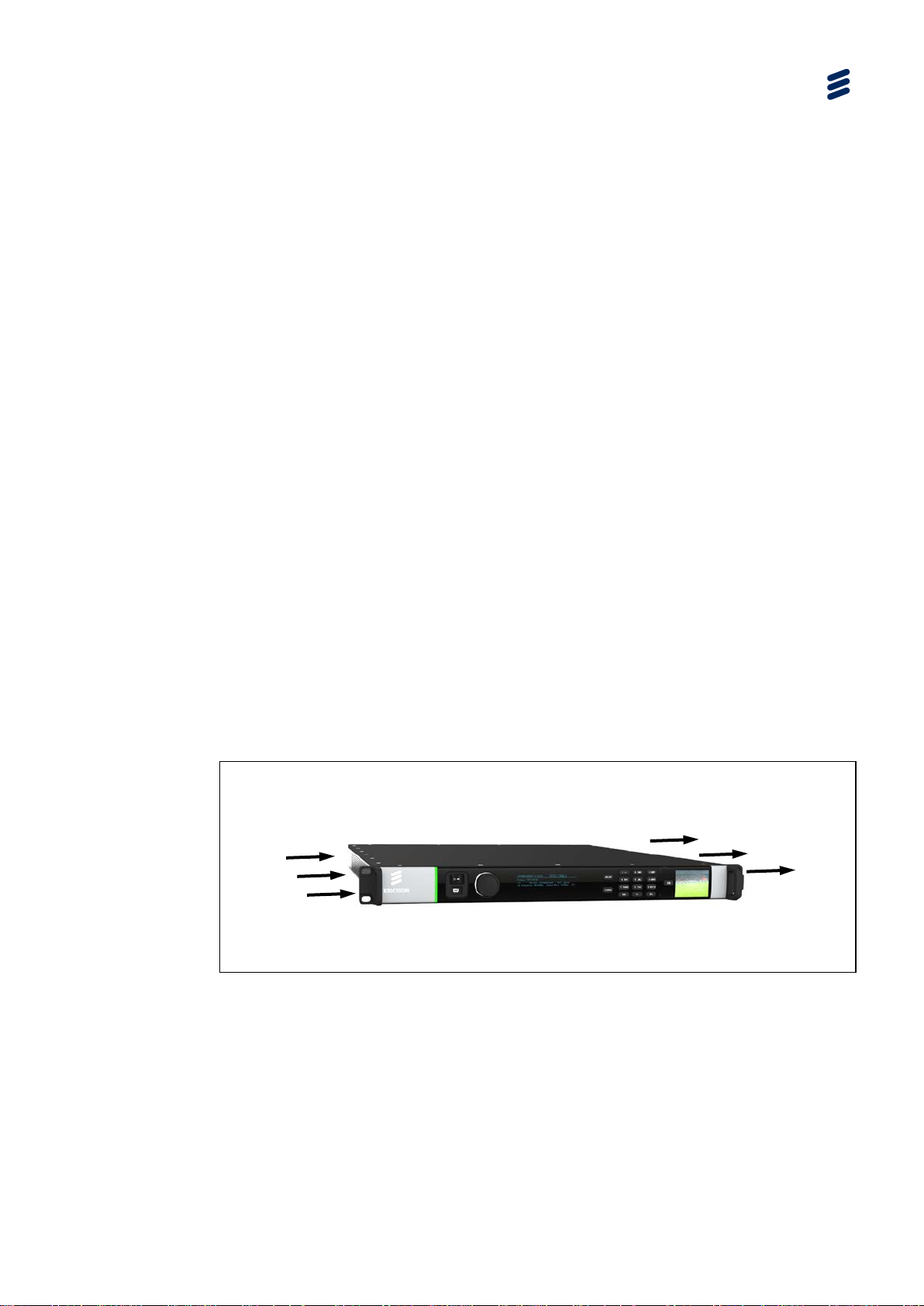
Power Switch
Light Bar
Mini USB
Rotary Knob
Main Display
Keypad
Confidence Monitor
• Power switch.
• Tri-color light bar to indicate chassis health.
• Dual redundant Ethernet control ports.
• Dual redundant Ethernet ports for data input and output.
• Option card slots (the number of option cards that may be fitted is different for
each base unit).
• Option cards are ‘hot swappable’.
• Confidence monitor for monitoring input video stream.
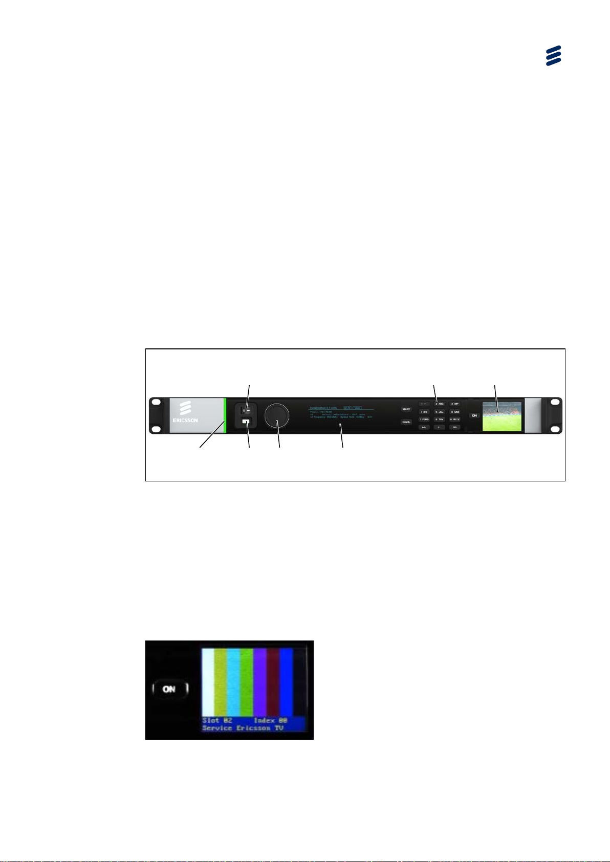
1.3 Front Panel
The front panel of the unit consists of a power switch, a confidence monitor, a light
bar, an USB Connector, a rotary knob, a main display and a keypad.
Introduction
Figure 1.1 Front Panel
1.3.1 Power Switch
The mains switch is recessed to prevent accidental switch-off.
1.3.2 Confidence Monitor
The confidence monitor allows the user to monitor the selected input video signal.
Figure 1.2 Confidence Monitor

1-12
EN/LZT 790 0023/1 R16A
Introduction
The confidence monitor is a 1.8 inch TFT LCD. The On key on the confidence
monitor turns the monitor on or off. By pressing and holding the On key, operation
related data is shown. The first line displays the total number of hours the monitor
has been operating; the second line displays the software version. The source of the
video to be displayed, the sleep timeout time and the monitor brightness can be set
up through the front panel or the web user interface. For details on how to configure
the settings for the confidence monitor see Chapter 3, Getting Started.
Note: The AVP 1000 (1RU) does not have a VCM fitted so although fitted, the
Confidence Monitor is not relevant for this model unless subsequently
upgraded to AVP 2000 functionality.
1.3.3 Light Bar
The light bar is green when there are no active alarms or warnings and red if there is
a critical alarm. The light bar is yellow if there is an active warning, minor or major
alarm.
1.3.4 USB Connector
The USB connector provides an interface for saving or exporting configurations to,
and loading or importing configuration from an USB stick. Moreover, by applying an
USB-Ethernet adaptor, the Ethernet port of a control computer can be connected to
the USB connector on the Front Panel of the unit.
1.3.5 Rotary Knob
The rotary knob is used for scrolling through and selecting the menu items.
1.3.6 Main Display
Control and status information is displayed on a graphic VFD display.
1.3.7 Keypad
Select and Cancel keys, as well as a numeric keypad is provided for interaction.
EN/LZT 790 0023/1 R16A
1-13
1.4 Base Chassis Options
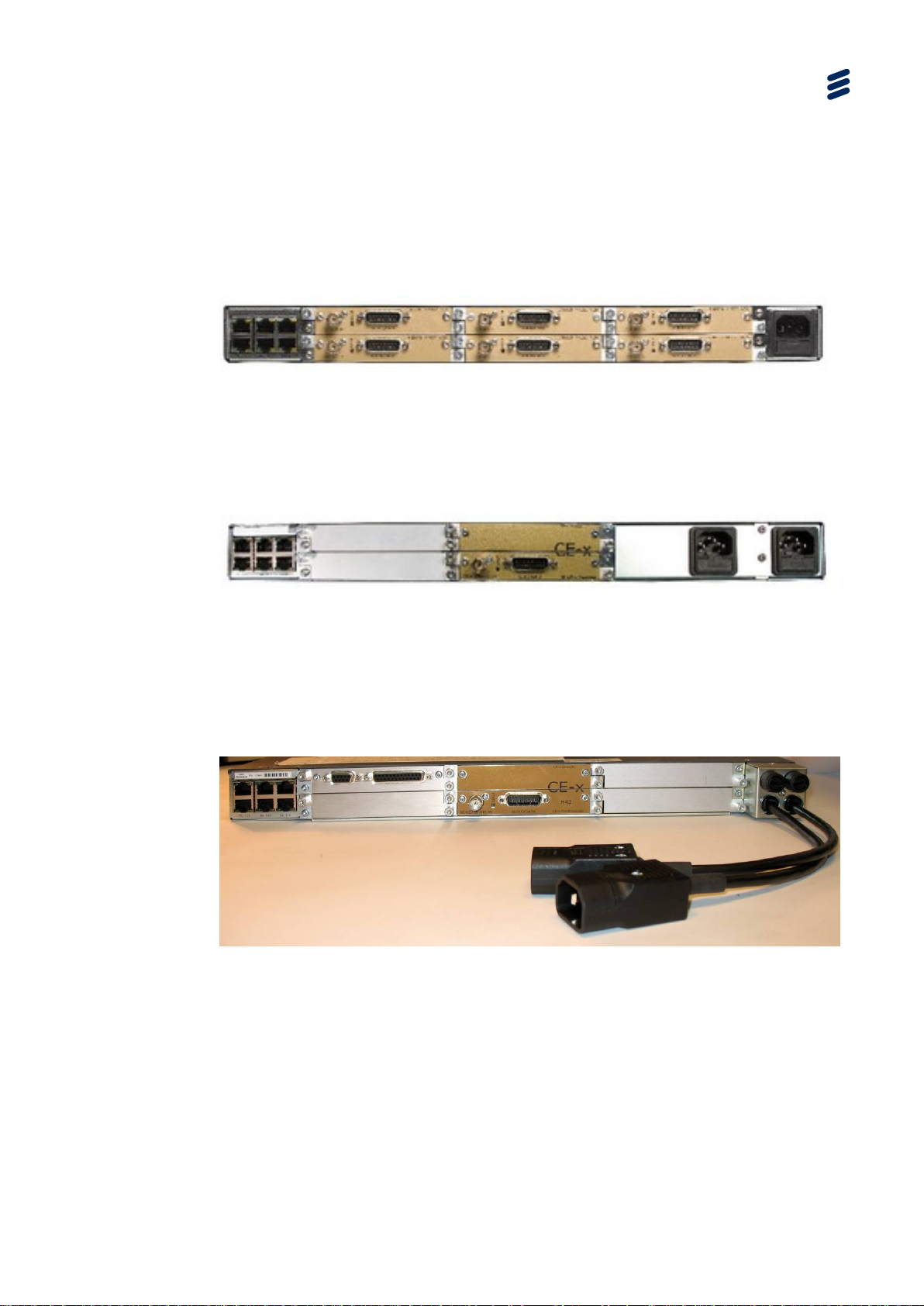
1.4.1 AVP****/BAS/1AC 1U Base Chassis
This chassis option provides a single mains input and slots for up to six option
cards.
Figure 1.3 AVP****/BAS/1AC Rear Panel with Six Option Cards Fitted
1.4.2 AVP****/BAS/2AC 1U Base Chassis
This chassis option provides a dual mains input and slots for up to four option cards.
Introduction
Figure 1.4 AVP****/BAS/2AC Rear Panel with One CE-x Option Card Fitted
1.4.3 AVP****/BAS/2ACFL 1U Base Chassis
This chassis option provides dual mains input via flying leads and slots for up to six
option cards.
Figure 1.5 AVP****/BAS/2ACFL Rear Panel with Two Option Cards Fitted
1.5 License Keys
Licenses control the availability of some of the features accessible from the unit.
A License Key consists of a feature, and the number of instances of this feature that
are allowed within the chassis or option card.

1-14
EN/LZT 790 0023/1 R16A
Introduction
License Keys are allocated on a ‘first configured first served’ basis. If an attempt is
made to enable a feature, but the required license key is not available then the
feature is not enabled, and a log message is generated.

EN/LZT 790 0023/1 R16A
2-1
2 Installing the Equipment
Chapter 2
Contents
2.1 Read This First! ................................................................................... 2-3
2.2 Mounting and Ventilation ..................................................................... 2-3
2.2.1 Fixing and Rack Mounting ................................................................... 2-3
2.2.2 Ventilation ........................................................................................... 2-3
2.3 Signal Connections.............................................................................. 2-4
2.3.1 Rear Panel Signal Connectors ............................................................ 2-4
2.3.2 Data Ethernet Connector ..................................................................... 2-5
2.3.3 Control Ethernet Connector ................................................................. 2-6
2.3.4 CE Option Modules ............................................................................. 2-7
2.3.4.1 Digital Video Input (All CE-a and CE-x Option Modules) ...................... 2-7
2.3.4.2 Digital Video Input (CE-HEVC/BNC Option Module) ............................ 2-8
2.3.4.3 Digital Video Input (CE-HEVC/SFP Option Module) ............................ 2-8
2.3.4.4 Analogue Video Input via the CVBS Interface (CE-xA) ........................ 2-9
2.3.4.5 Digital Audio Input Connector (All CE-a and CE-x Option Modules) .... 2-9
2.3.4.6 Analogue Audio Input via the 15-way D-type Connector (CE-xA) ...... 2-11
2.3.5 Satellite Modulator Option Card Connectors ...................................... 2-13
2.3.6 ASI I/O Option Card Connectors........................................................ 2-14
2.3.7 G.703 Transceiver Option Card Connectors ...................................... 2-15
2.3.8 External Sync Input Option Card Connector ...................................... 2-15
2.3.9 GPI Option Card Connectors ............................................................. 2-16
2.3.10 Mini USB Connector .......................................................................... 2-17
List of Figures
Figure 2.1 Air-Flow through the Equipment .......................................................... 2-3
Figure 2.2 Rear Panel With CE-x VCM, SatMod and ASI I/O Options Fitted ........ 2-4
Figure 2.3 Satellite Modulator Option Card Rear Panel ...................................... 2-13
Figure 2.4 ASI I/O Option Card ........................................................................... 2-14
Figure 2.5 G.703 Option Card Rear Panel .......................................................... 2-15
Figure 2.6 External Sync Input Option Card ....................................................... 2-15
Figure 2.7 Mini USB Connector .......................................................................... 2-17
List of Tables
Table 2.1 Data Ethernet Connector ..................................................................... 2-5
Table 2.2 Link Speed: Left (Green) LED ............................................................. 2-5
Table 2.3 Link Activity: Right (Yellow) LED.......................................................... 2-5

2-2
EN/LZT 790 0023/1 R16A
Installing the Equipment
Table 2.4 Control Ethernet Connector................................................................. 2-6
Table 2.5 Port Status: Left (Green) LED ............................................................. 2-6
Table 2.6 Link Activity: Right (Yellow) LED ......................................................... 2-7
Table 2.7 Digital Video I n p ut via the SDI/HD-S DI Interface ................................. 2-7
Table 2.8 Lock LED State Descriptions ............................................................... 2-7
Table 2.9 Digital Video Input via the SDI Interface .............................................. 2-8
Table 2.10 Lock LED State Descriptions ............................................................... 2-8
Table 2.11 Digital Video Input via the SDI/HD-SDI Interface ................................. 2-8
Table 2.12 Lock LED State Descriptions ............................................................... 2-9
Table 2.13 Analogue Video Input via the CVBS Interface ..................................... 2-9
Table 2.14 CVBS LED State Descriptions ............................................................ 2-9
Table 2.15 Audio Breakout Cables ....................................................................... 2-9
Table 2.16 Breakout Cable Detection Criteria ..................................................... 2-10
Table 2.17 Digital Audio Input (Balanced) ........................................................... 2-10
Table 2.18 Digital Audio Input (Unbalanced) ....................................................... 2-11
Table 2.19 Audio Breakout Cables ..................................................................... 2-11
Table 2.20 Breakout Cable Detection Criteria ..................................................... 2-12
Table 2.21 Analogue Audio Input (Balanced) ...................................................... 2-12
Table 2.22 Analogue Audio Input (Unbalanced) .................................................. 2-13
Table 2.23 Satellite Modulator Option Card Connectors ..................................... 2-14
Table 2.24 ASI I/O Option Card Connectors ....................................................... 2-14
Table 2.25 G.703 Transceiver Option Card Connectors ..................................... 2-15
Table 2.26 External Sync Input Option Card Connector ...................................... 2-15
Table 2.27 GPI Data In Connector (Not supported in this release) ...................... 2-16
Table 2.28 GPI Alarm Contact Closure Connector .............................................. 2-16
Table 2.29 Data Input Connector Pin-out ............................................................ 2-17
EN/LZT 790 0023/1 R16A
2-3
Air is released
Fans are
2.1 Read This First!
Please refer to the Installation, Safety and Compliance Information for Ericsson
Compression Products Reference Guide supplied with your product for full details of
installation requirements. This guide only contains additional product specific
information where required.
2.2 Mounting and Ventilation
2.2.1 Fixing and Rack Mounting
The equipment is designed for fixed use only and has been shipped with fixing
brackets suitable for a standard 19-inch rack. When installed in a rack, it should be
secured using the fixing brackets. In addition, support shelves must be used to
reduce the weight on the brackets. Ensure it is firmly and safely located and it has
an adequate free-flow of air.
Installing the Equipment
Slide the unit onto the chassis supports and affix to the rack by means of an
M6 x 18 mm panhead screw in each corner.
A freestanding unit should be installed on a secure horizontal surface where it is
unlikely to be knocked or its connectors and leads disturbed.
2.2.2 Ventilation
Side openings in the unit, as well as side-mo unted cooli ng fans , are prov ided fo r
ventilation. They ensure reliable ope ration of the product and protec t it from
overheating. The openings of the fans m us t no t be blocked or cover ed.
mounted on
this side of
the unit
Figure 2.1 Air-Flow through the Equipment
through vents at
the side of the unit.
2-4
EN/LZT 790 0023/1 R16A
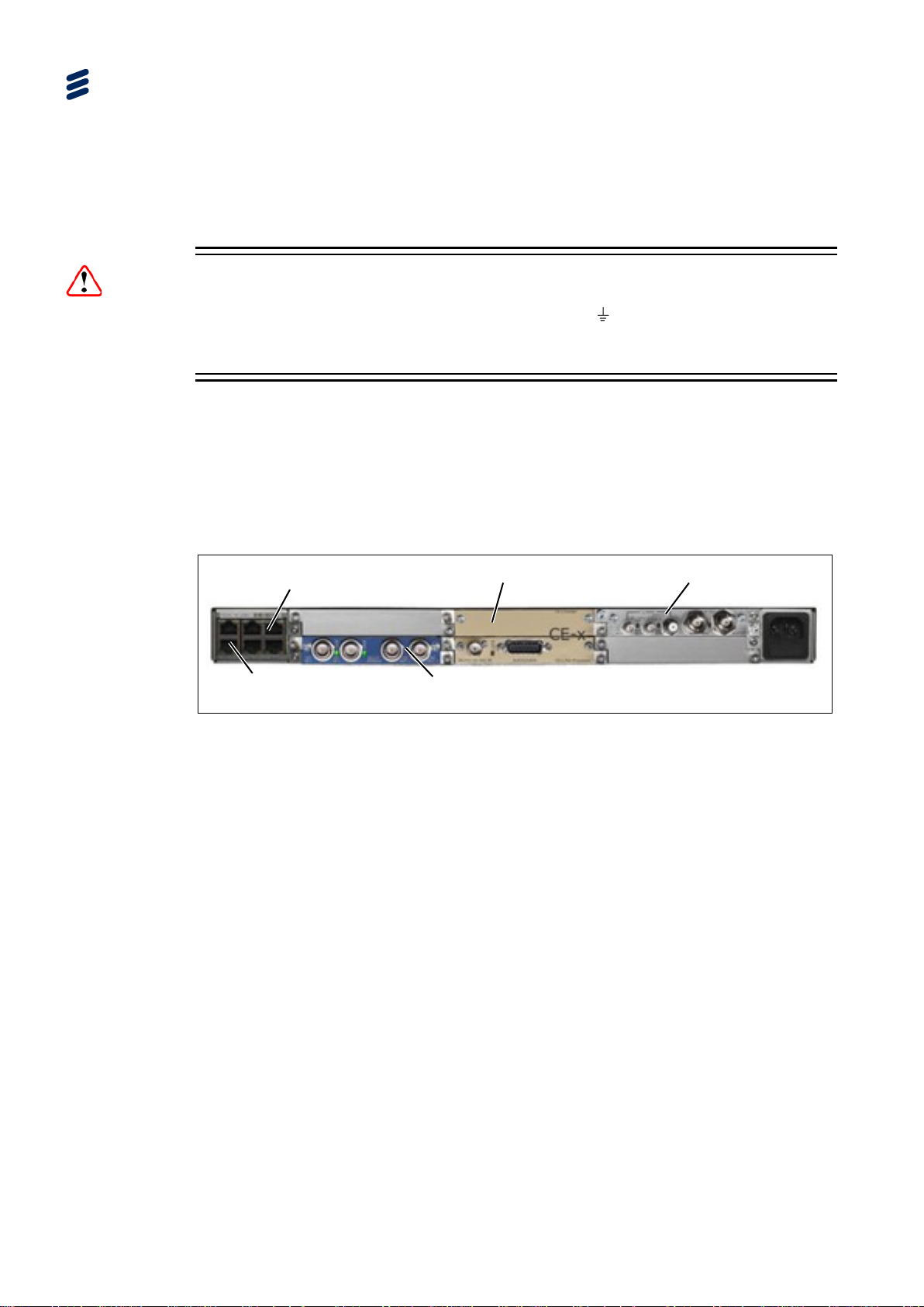
Data Ethernet (x4)
Control Ethernet (x2)
SatMod
ASI I/O Module
CE-x VCM
Installing the Equipment
2.3 Signal Connections
2.3.1 Rear Panel Signal Connectors
It is strongly recommended that the terminal marked at the rear panel of the
equipment is connected to a site Technical Earth before any external connections
are made and the equipment is powered. This limits the migration of stray charges.
Signal connections are made via the rear panel. The rear panels, which are
available are shown below. Full technical specifications for the connections are
given in Annex B.
Only the Data and Control Ethernet connectors and the PSU connectors are
mounted on the chassis. All other connections at the rear panel are provided with
the option modules that may be fitted. Examples are shown below.
Caution!
Figure 2.2 Rear Panel With CE-x VCM, SatMod and ASI I/O Options Fitted
EN/LZT 790 0023/1 R16A
2-5
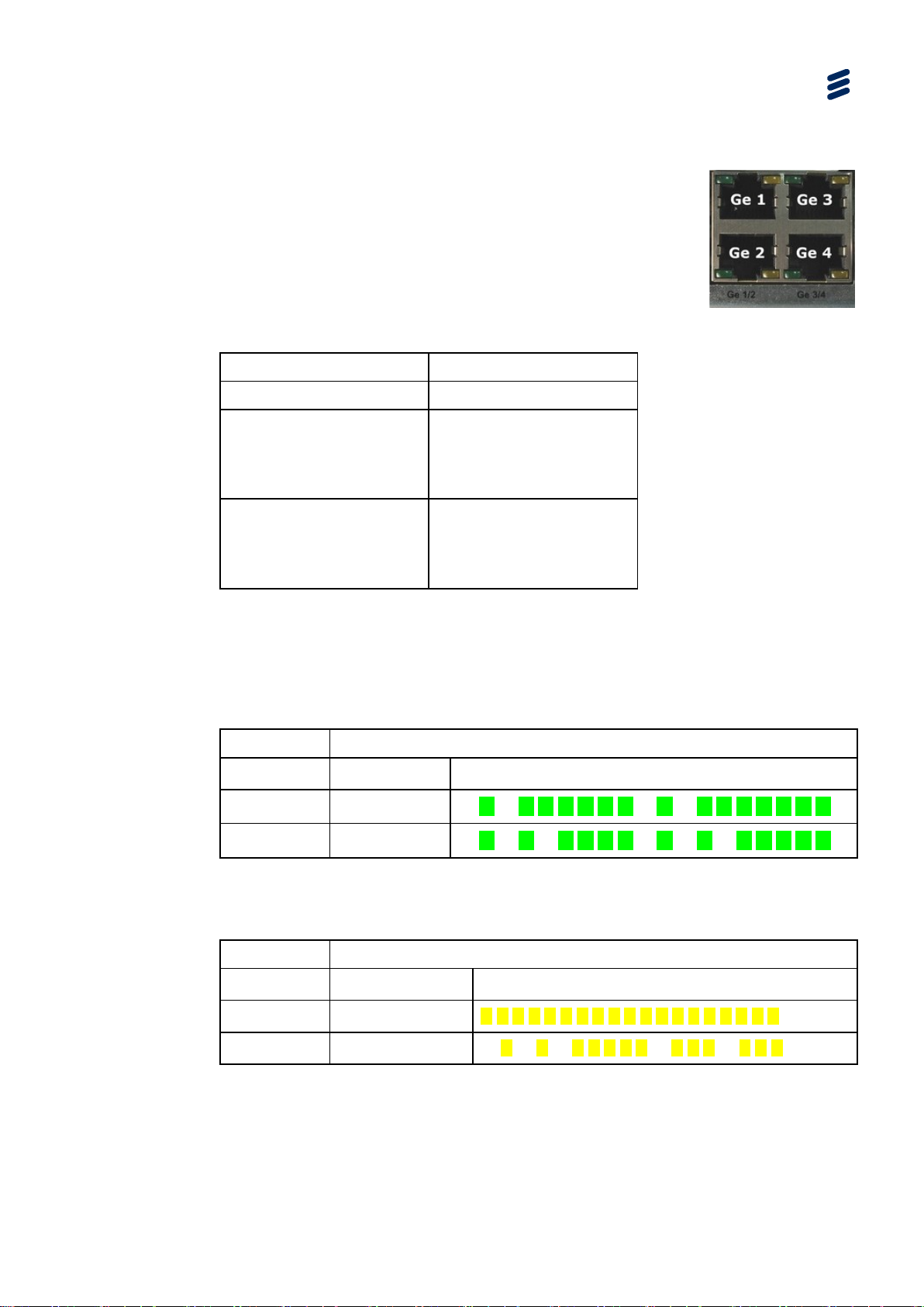
2.3.2 Data Ethernet Connector
The unit has four Ethernet ports - two for data input, and
two for data output and will respond to ARPs, pings and
other low-level Ethernet traffic. The ports are accessible
via RJ-45 connectors on the rear panel of the chassis.
These are labeled Ge 1, Ge 2, Ge 3 and Ge 4. Ge 1 and
Ge 2 are used for data input, while Ge 3 and Ge 4 are
data output.
Table 2.1 Data Ethernet Connector
Item Specification
Connector type RJ-45 (100/1000 Base T)
Connector designation Ge 1 (data input)
Installing the Equipment
Ge 2 (data input)
Ge 3 (data output)
Ge 4 (data output)
Pin outs
(Unused pins are not connected)
Pin 1 - T x Out (+)
Pin 2 - Tx Out (-)
Pin 3 - Rx In (+)
Pin 6 - Rx In (-)
Status and Activity Indication
Each Ethernet Data Port has a rear panel mounted status LED associated with it to
indicate link status, activity and speed as follows:
Table 2.2 Link Speed: Left (Green) LED
Link Speed LED Status
No Link Off
100 Mbps Flash Off x 2
1000 Mbps Flash Off x 3
— — — — — — — — — — — — — — — — — —
— ☐ — ☐ ☐ ☐ ☐ ☐ ☐ — ☐ — ☐ ☐ ☐ ☐ ☐ ☐ ☐
— ☐ — ☐ — ☐ ☐ ☐ ☐ — ☐ — ☐ — ☐ ☐ ☐ ☐ ☐
The left LED flash sequence period is 1 s, with a short flash duration of 100 ms.
Table 2.3 Link Ac tivity: Right (Yellow) LED
Link Speed LED Status
No Link Off
Link On
Activity Flash
— — — — — — — — — — — — — — — — — —
☐ ☐ ☐ ☐ ☐ ☐ ☐ ☐ ☐ ☐ ☐ ☐ ☐ ☐ ☐ ☐ ☐ ☐ ☐
— ☐ — ☐ — ☐ ☐ ☐ ☐ ☐ — ☐ ☐ ☐ — ☐ ☐ ☐
2-6
EN/LZT 790 0023/1 R16A
Installing the Equipment
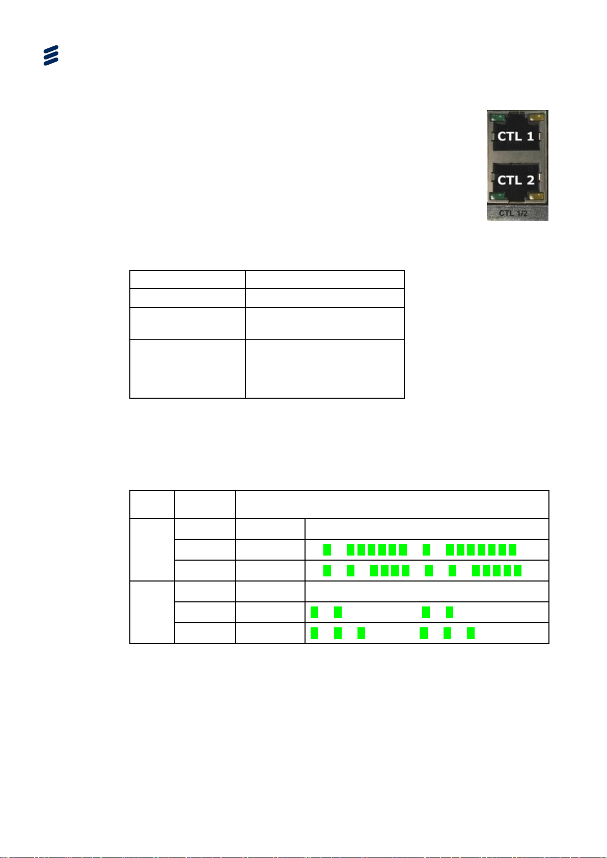
2.3.3 Control Ethernet Connector
The Ethernet control ports are used to connect the
equipment to a PC for access with a web browser. Both
connectors share the same IP address, CTL 1 is the
Primary control port, and is by default the active control
port. Control Port CTL 2 should be considered as the
secondary control network as it will not respond to the
Control Port IP Address unless control has been passed
to it either as a result of a redundancy switch, or via a
user command. The active control port switches when
CTL 1 has no link (e.g. carrier), and CTL 2 has the link.
Table 2.4 Control Et hernet Connector
Item Specification
Connector type RJ-45 (100/1000 Base T)
Connector designation CT L 1
CTL 2
Pin outs
(Unused pins are not
connected)
Pin 1 - Tx Out (+)
Pin 2 - Tx Out (-)
Pin 3 - Rx In (+)
Pin 6 - Rx In (-)
Status and Activity Indication
Each Ethernet Control Port has rear panel mounted status LEDs to indicate link
status, activity and speed as follows:
Table 2.5 Port Status: Left (Green) LED
Port
Status
Active
Port
Spare
Port
Link Speed LED Status
No Link Off
100 Mbps Flash Off x 2
1000 Mbps Flash Off x 3
No Link Off
100 Mbps Flash On x 2
1000 Mbps Flash On x 3
— — — — — — — — — — — — — — — — — —
— ☐ — ☐ ☐ ☐ ☐ ☐ ☐ — ☐ — ☐ ☐ ☐ ☐ ☐ ☐ ☐
— ☐ — ☐ — ☐ ☐ ☐ ☐ — ☐ — ☐ — ☐ ☐ ☐ ☐ ☐
— — — — — — — — — — — — — — — — — —
☐ — ☐ — — — — — — ☐ — ☐ — — — — — —
☐ — ☐ — ☐ — — — — ☐ — ☐ — ☐ — — — —
The left LED flash sequence period is 1 s, with a short flash duration of 100 ms.
 Loading...