

Page 1

Unlicensed LPWA Gateway 5780
Technical information
USER GUIDE
1/1553-KRC 161 673 UEN Rev PB9
Page 2

Unlicensed LPWA Gateway 5780
1/1553-KRC 161 673 UEN Rev PB9 2017-03-24
Ericsson AB 2017
2 (45)
Commercial in confidence
Contents
1 Introduction ................................................................................. 4
1.1 Connectors ................................................................................... 5
2 Safety Information ...................................................................... 6
3 Preparing for Installation ............................................................ 6
3.1 Required Tools ............................................................................. 6
3.2 Conditions ..................................................................................... 8
4 Unpack and Check Materials...................................................... 8
5 Installation Alternatives Overview ........................................... 10
5.1 Accessories for Gateway 5780 .................................................... 10
6 Install Gateway .......................................................................... 17
6.1 Wall Installation ........................................................................... 17
6.2 Pole Installation for Wall plate and Support ................................. 23
6.3 Install Support 6501 .................................................................... 24
6.4 Connecting the Cables ................................................................ 26
6.5 Connecting Antennas .................................................................. 34
7 Management .............................................................................. 35
7.1 SNMP Management Interface ..................................................... 35
7.2 Gateway 5780 Configuration management ................................. 35
7.3 Mobile network subscription (WWAN backhaul option) ............... 37
7.4 Fault management ...................................................................... 37
7.5 Performance management .......................................................... 39
7.6 Hardware management............................................................... 39
7.7 Software management ................................................................ 40
7.8 Security Management ................................ ................................. 40
8 References ................................................................................ 41
9 Terminology .............................................................................. 41
10 Document History ..................................................................... 41
11 Appendix A. FCC/ISED Regulatory notices ............................. 42
12 Appendix B. European Union, EU Declaration of
Conformity ................................................................................. 44
Page 3

Unlicensed LPWA Gateway 5780
1/1553-KRC 161 673 UEN Rev PB9 2017-03-24
Ericsson AB 2017
3 (45)
Commercial in confidence
Copyright
© Ericsson AB 2017. All rights reserved. No part of this document may be
reproduced in any form without the written permission of the copyright owner.
Disclaimer
The contents of this document are subject to revision without notice due to
continued progress in methodology, design and manufacturing. Ericsson shall
have no liability for any error or damage of any kind resulting from the use of
this document.
Page 4
Unlicensed LPWA Gateway 5780
1/1553-KRC 161 673 UEN Rev PB9 2017-03-24
Ericsson AB 2017
4 (45)
Commercial in confidence
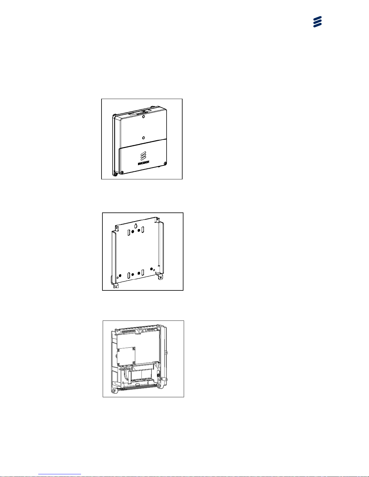
1 Introduction
This document describes how to install the Unlicensed LPWA Gateway 5780
on site. The Gateway 5780 can be installed on a wall or on a mast, using a
Support 6501 with built-in AC power supply or a wall plate.
Figure 1 Gateway 5780
Figure 2 Wall plate
Figure 3 Support 6501
Page 5
Unlicensed LPWA Gateway 5780
1/1553-KRC 161 673 UEN Rev PB9 2017-03-24
Ericsson AB 2017
5 (45)
Commercial in confidence
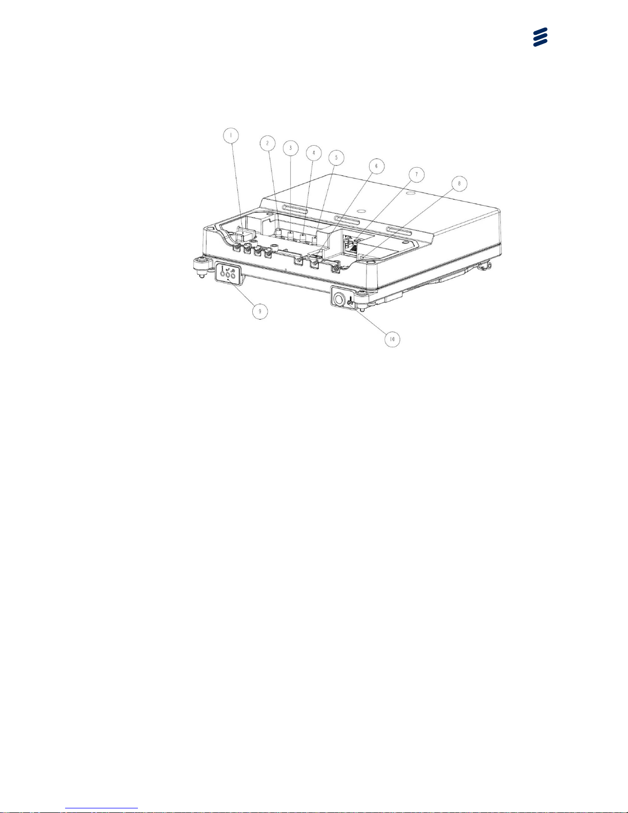
1.1 Connectors
Figure 4 Connectors
Item Description
1 Local Management Port (Local O&M), USB type B
2 WWAN Diversity antenna port (Backhaul)
3 WWAN Main antenna port (Backhaul)
4 GNSS antenna port (GPS)
5 LoRaWAN™ antenna port
6 SIM card slot (WWAN backhaul option)
7 RJ45 Socket for Ethernet (ETH backhaul) and optional PoE input.
8 3-wire DC supply (DC/I), to be connected to the optional Support
6501 (including PSU)
9 LED indicator display (3 LEDs)
10 Chassis grounding point
Page 6

Unlicensed LPWA Gateway 5780
1/1553-KRC 161 673 UEN Rev PB9 2017-03-24
Ericsson AB 2017
6 (45)
Commercial in confidence
2 Safety Information
Make sure that the information in the below documents has been read and
understood by the persons performing the procedures:
Personal Health and Safety Information [1]
System Safety Information [2]
3 Preparing for Installation
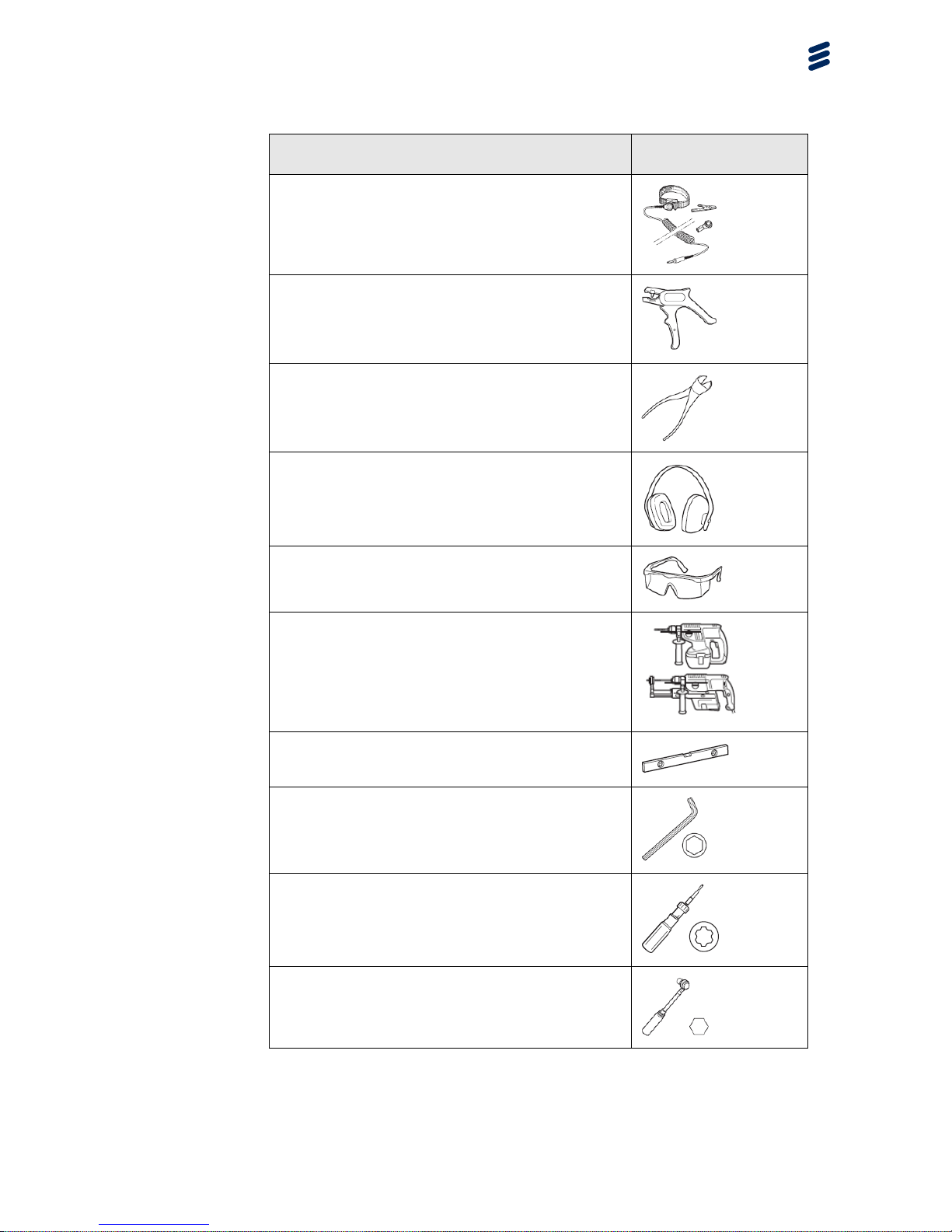
3.1 Required Tools
Required tools for installing the gateway are listed in Figure 5 Tools
requiredFigure 5 below.
Page 7
Unlicensed LPWA Gateway 5780
1/1553-KRC 161 673 UEN Rev PB9 2017-03-24
Ericsson AB 2017
7 (45)
Commercial in confidence
Product Name
Tool
Electrostatic Discharge (ESD) wrist strap (static
control wrist strap)
Wire stripper 0.2–6.0 mm
Side cutter
Ear protection
Eye protectors
One of the following (Wall mounting):
• Hammer drill 230 V AC
• Cordless hammer drill, with 230 V AC charger
Hammer drills for voltages other than 230 V AC
cannot be ordered from Ericsson
Spirit level
Allen key, 5 mm
Torque wrench (0.5 Nm), flat screwdriver 2 mm
Torque wrench 0.5–4 Nm,
TORX® T10, TORX® T20 TORX® T30
Torque wrench 5–25 Nm, socket 13 mm
Figure 5 Tools required
Page 8

Unlicensed LPWA Gateway 5780
1/1553-KRC 161 673 UEN Rev PB9 2017-03-24
Ericsson AB 2017
8 (45)
Commercial in confidence
3.2 Conditions
The conditions in this section must be fulfilled before work starts.
3.2.1 Before Going to the Site
Before going to site, make sure below items are available:
Site access permission has been received.
Documentation stated in section 2, ‘Safety Information’ is available.
All applicable tools stated in section, 3.1 ‘Required Tools’ are available
3.2.2 Before Starting the Installation
Before starting the installation, make sure below list is completed:
The site is prepared per the Site Installation Documentation.
The ordered hardware is available.
The power supply for the gateway is installed and tested at the
gateway site.
The site grounding system is installed and tested.
Either of the following alternatives must be installed and tested:
- A main switch and an external fuse
- A circuit breaker
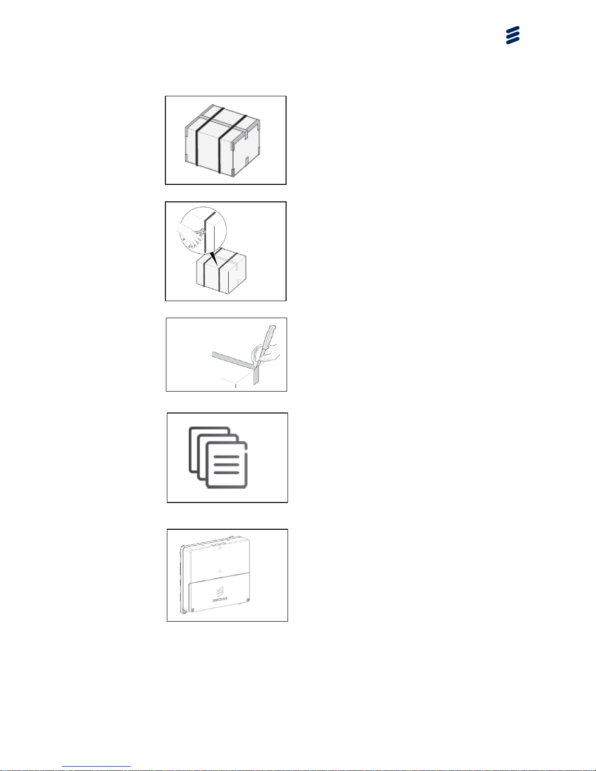
4 Unpack and Check Materials
The gateway components are transported in corrugated boxes. Do not
dispose of the packaging as it can be required to return faulty equipment.
Steps
To unpack and check the materials, do the following:
Page 9
Unlicensed LPWA Gateway 5780
1/1553-KRC 161 673 UEN Rev PB9 2017-03-24
Ericsson AB 2017
9 (45)
Commercial in confidence
1. Examine the packaging for damage. If
it is damaged, immediately register a
complaint with the transport company. It
is recommended that a photo of the
damages be taken to improve the
claim process.
2. Remove the straps from the
corrugated box.
3. Remove the tape from the
corrugated box.
Note:
Make sure that the items in the
corrugated box is not damaged.
4. Check that the items delivered
correspond to the packing list.
5. Carefully place the gateway
components on the ground on a clean,
soft surface, or on the packaging material.
Note:
Make sure to keep the gateway
components clean from moisture and dirt.
Page 10
Unlicensed LPWA Gateway 5780
1/1553-KRC 161 673 UEN Rev PB9 2017-03-24
Ericsson AB 2017
10 (45)
Commercial in confidence
5 Installation Alternatives Overview
The installation alternatives for the gateway are shown in below sections and
pictures.
Note: Antennas and equipment must be installed in a location protected from
direct lightning strikes which means it must be installed inside a lightning
protective zone formed of lightning conductors, buildings, antenna tower, and
so on. For more information, see document Grounding Guidelines for RBS
Sites, 23/1551-LZA 701 6009, reference [3].
The GNSS active antenna and the RF cable must not be installed close to
lightning conductors, which can carry currents from direct lightning strikes.
The regulatory testing for Gateway 5780 was conducted with the stated
antennas in Table 1 installed and present. To be in compliance with regulatory
requirements Ericsson state that installers and users of this Gateway 5780
must only use antennas of a similar type and with the same or lower gain.
Note that the antenna gain must be configured during installation for correct
maximum output power. See also chapter 7.2.4.
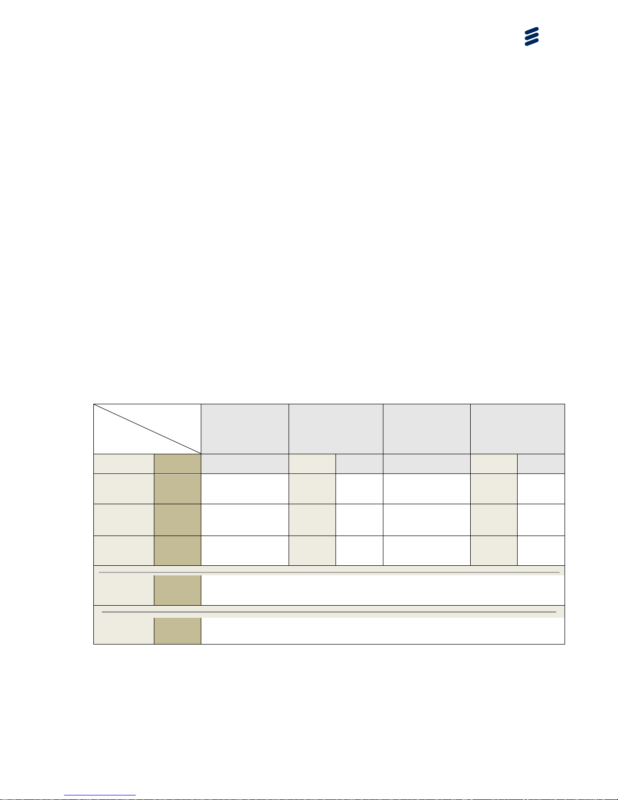
5.1 Accessories for Gateway 5780
Table 1, overview summary of Gateway 5780 and electrical accessory
combinations
Gateway 5780,
KRC161673/10
(EU without
WWAN)
Gateway 5780,
KRC161673/11
(EU with EM7305,
WWAN module, RYT
142 7016/1)
Gateway 5780,
KRC161673/20
(US without
WWAN)
Gateway 5780,
KRC161673/21
(US with EM7355,
WWAN module, RYT
142 7017/1))
Name
Part No
@LoRa®
RF port
@LoRa®
RF port
@WWAN
port
@LoRa®
RF port
@LoRa®
RF port
@WWAN
port
Omni
antenna, 11
dBi gain
KRE 101
1399/1
N/A
(US band)
N/A
(US
band)
N/A
Yes
Yes
N/A
Omni
antenna, 11
dBi gain
KRE 101
1685/1
Yes
Yes
N/A
N/A
(EU band)
N/A
(EU
band)
N/A
Omni
antenna,
2dBi gain
KRE 101
2233/1
Yes
Yes
Yes
Yes
Yes
Yes
GPS active
antenna,
35±5dBi
KRE 101
2182/1
Yes, supported for all variants @ GNSS antenna RF port.
Support
Frame 6501
KRY 901
345/1
Yes, supported Power option for all variants. (including mechanical mounting).
Page 11
Unlicensed LPWA Gateway 5780
1/1553-KRC 161 673 UEN Rev PB9 2017-03-24
Ericsson AB 2017
11 (45)
Commercial in confidence
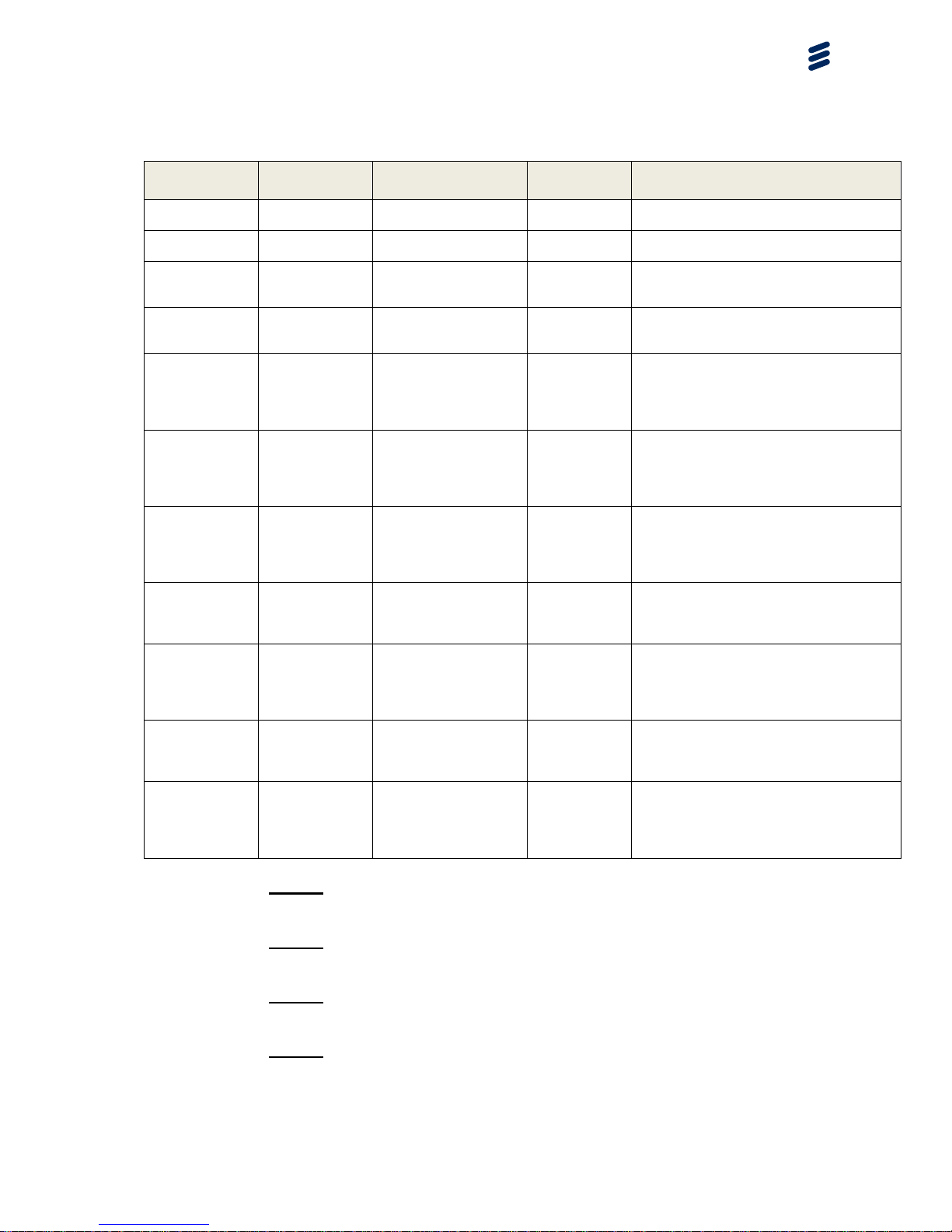
Table 2, Component list with product numbers
Name
Ericsson
number
Technical summary
Description
Note:
Omni antenna,
11 dBi gain
KRE 101 1399/1
Omni, V-pol, 870-960
MHz, 11 d
LoRa® RX
and TX
Omni antenna,
11 dBi gain
KRE 101 1685/1
Omni, V-pol, 806-894
MHz, 11 d
LoRa® RX
and TX
Omni antenna,
2dBi gain
KRE 101 2233/1
V-pol, 790-960+16952700 MHz
LoRa® RX
and TX OR
WWAN
Dual band low gain antenna, LoRa® and
WWAN capable. (2 pcs needed for both
LoRa® and WWAN)
GPS active
antenna,
35±5dBi
KRE 101 2182/1
1565.42MHz
~1585.42MHz*
GPS RX (LNA
included)
*) Note that the GNSS receiver included in
Gateway 5780 is supporting 1551MHz to
1614MHz.
EM7305,
WWAN Module
(sub part of
Gateway 5780,
KRC161673/11)
RYT 142 7016/1
Embedded module,
3G/4G bands
Sierra
Wireless,
EM7305
backhaul
option
LTE Bands: B1 (2100), B3 (1800), B7
(2600), B8 (900), B20 (800D)
UMTS Bands: 2100, 1900, 850, 900
GSM/EDGE Bands: 850, 900, 1800, 1900
EM7355,
WWAN Module
(sub part of
Gateway 5780,
KRC161673/21)
RYT 142 7017/1
Embedded module,
3G/4G bands
Sierra
Wireless,
EM7355
backhaul
option
LTE Bands: B2 (1900), B4 (AWS), B13
(700c), B17 (700bc), B5 (850), B25 (1900)
UMTS Bands: 2100, 1900, 850, 900, 1700
GSM/EDGE Bands: 850, 900, 1800, 1900
Support Frame
6501
KRY 901 345/1
AC to DC unit:
115/230V AC to
+36VDC
AC/DC
converter and
mechanical
mounting
interface
Gateway 5780,
EU,
without WWAN
KRC161673/10
LoRa® capable
Gateway for EU
unlicensed band
Ethernet LAN backhaul.
Gateway 5780
unit
LoRa® :863-870 MHz
GNSS receiver: 1551-1614MHz.
Gateway 5780,
EU with WWAN
KRC161673/11
LoRa® capable
Gateway for EU
unlicensed band
Ethernet LAN backhaul
OR WWAN backhaul.
Gateway 5780
unit
LoRa® :863 -870 MHz
GNSS receiver: 1551-1614MHz.
WWAN: see EM7305 above in table
Gateway 5780,
US
without WWAN
KRC161673/20
LoRa® capable
Gateway for US
unlicensed band
Ethernet LAN backhaul.
Gateway 5780
unit
LoRa® :902-928 MHz
(Channel frequencies, see LoRaWAN
specification)
GNSS receiver: 1551-1614MHz.
Gateway 5780,
US with WWAN
KRC161673/21
LoRa® capable
Gateway for US
unlicensed band
Ethernet LAN backhaul
OR WWAN backhaul.
Gateway 5780
unit
LoRa® :902-928 MHz
(Channel frequencies, see LoRaWAN
specification)
GNSS receiver: 1551-1614MHz.
WWAN: see EM7355 above in table
Note 1: The Gateway 5780 receiver is classified as a category 2 receiver as
per definition in ETSI EN 300 220-1, ref. [4].
Note 2: Sierra Wireless module “model: 7355” has already been certified in
USA and Canada, under FCC ID: N7NEM7355 and IC: 2417C-EM7355.
Note 3: Sierra Wireless module “model: 7305” has already been CE marked
for the EU.
Note 4: Simultaneous transmission between the cellular WWAN module and
the LoRa® transmitter is possible.
Page 12

Unlicensed LPWA Gateway 5780
1/1553-KRC 161 673 UEN Rev PB9 2017-03-24
Ericsson AB 2017
12 (45)
Commercial in confidence
Page 13
Unlicensed LPWA Gateway 5780
1/1553-KRC 161 673 UEN Rev PB9 2017-03-24
Ericsson AB 2017
13 (45)
Commercial in confidence
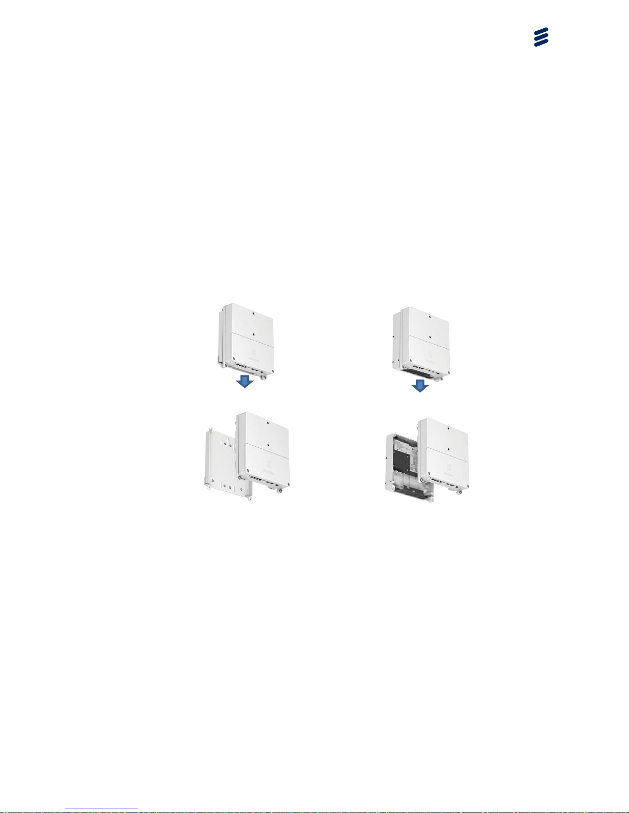
5.1.1 Mounting and power
The Gateway 5780 has 2 different power feeding options:
1. Integrated 115/230V AC power is possible with Support Frame 6501
(Ericsson product number KRY 901 345/1) and Gateway 5780 main unit.
I.e. DC input on Gateway 5780 is fed from the Support frame 6501
(including a PSU).
Note: This installation requires external fuse and circuit breaker. The
recommended melting fuse type is gG-gL-gD in accordance with
IEC 60269-1. Circuit breakers must comply with at least Curve 3 tripping
characteristics, in accordance with IEC 60934. Minimum fuse rating 6A.
2. Power over Ethernet (PoE), per IEEE 802.3af.
Note: It is required that fusing and over voltage protection is covered via
the installation of the Power over Ethernet (PoE) injector.
Figure 6 Power alternatives, PoE configured and support 6501 AC-configured
site
The support 6501 is designed to fit both mechanically and electrically together
with Gateway 5780.
The wall plate for either mast or Wall installation option will utilize a simple and
highly integrated mechanical solution.
Page 14
Unlicensed LPWA Gateway 5780
1/1553-KRC 161 673 UEN Rev PB9 2017-03-24
Ericsson AB 2017
14 (45)
Commercial in confidence
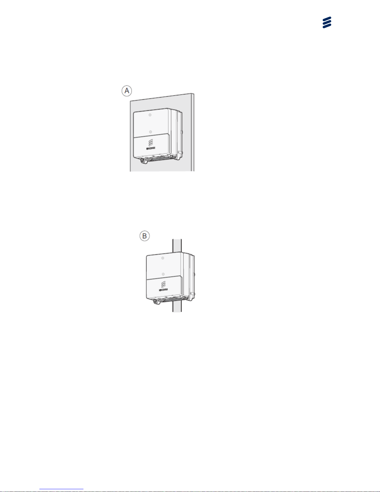
5.1.2 Mechanical Gateway Installation
5.1.2.1 Wall mount installation
Figure 7 Wall Mount
5.1.2.2 Pole mount installation
Figure 8 Pole Mount
Page 15

Unlicensed LPWA Gateway 5780
1/1553-KRC 161 673 UEN Rev PB9 2017-03-24
Ericsson AB 2017
15 (45)
Commercial in confidence
5.1.3 Antenna Alternatives
The examples below show some typical form factor antennas.
Always follow the guidelines from Ericsson regarding the supported antenna
solutions.
5.1.3.1 Small Form Factor Antennas, e.g. 2 dBi LoRa® antenna
Figure 9 Dual 2 dBi antennas, LoRa®(A) and WWAN Backhaul
5.1.3.2 Large Form Factor antennas, e.g. 11 dBi LoRa® antenna.
Figure 10 LoRa® feeder cable, antenna and surge protector according to
recommended site material kit NTC 101 02/1 to be connected to B
Page 16

Unlicensed LPWA Gateway 5780
1/1553-KRC 161 673 UEN Rev PB9 2017-03-24
Ericsson AB 2017
16 (45)
Commercial in confidence
5.1.4 Power Alternatives
5.1.4.1 Support 6501
Figure 11 115/230 AC power alternative
5.1.4.2 Power over Ethernet
Figure 12 Power over Ethernet alternative
Page 17

Unlicensed LPWA Gateway 5780
1/1553-KRC 161 673 UEN Rev PB9 2017-03-24
Ericsson AB 2017
17 (45)
Commercial in confidence
6 Install Gateway
6.1 Wall Installation
6.1.1 Using Support 6501
The drilling overview for wall installation is shown below
Figure 13 Drilling Overview for wall installation
Steps
To install the gateway using a wall installation, do the following
1. Mark a hole in the wall for the upper hole
position on the gateway, and drill a hole. The
size and type of drill are specified in the site
installation plan. The maximum screw diameter
size is 6 mm.
Note: Wear protective equipment when drilling
Page 18

Unlicensed LPWA Gateway 5780
1/1553-KRC 161 673 UEN Rev PB9 2017-03-24
Ericsson AB 2017
18 (45)
Commercial in confidence
2. Insert a plug or an expander bolt into the
hole. Plugs or expander bolts are not
delivered with the unit. They must be
specified by the site installation plan.
3. Insert a screw in the hole, leaving
10 mm of the screw pointing out from the
wall. Use a flat washer.
5. Mark the holes using the two bottom
holes in the Support. Use a spirit level to
make sure the Support is in horizontal
level.
6. Unhook the Support from the wall.
4. Hook the Support onto the screw.
7. Drill holes in the wall at the markings
Page 19

Unlicensed LPWA Gateway 5780
1/1553-KRC 161 673 UEN Rev PB9 2017-03-24
Ericsson AB 2017
19 (45)
Commercial in confidence
Continue installation on 6.3 6.3Install Support
8. Insert a plug or an expander bolt into the
hole. Plugs or expander bolts are not delivered
with the unit. They must be specified by the site
installation plan.
9. Hook the Support onto the screw.
10. Insert screws in the holes.
11. Tighten the screws according to the
recommendations given by the site installation
plan.
Page 20

Unlicensed LPWA Gateway 5780
1/1553-KRC 161 673 UEN Rev PB9 2017-03-24
Ericsson AB 2017
20 (45)
Commercial in confidence
6.1.2 Using Wall plate
The drilling overview for wall installation is shown below
Figure 14 Drilling Overview
Steps
To install the gateway using a wall installation, do the following
1. Mark a hole in the wall for the upper hole
position on the gateway, and drill a hole. The
size and type of drill are specified in the site
installation plan. The maximum screw diameter
size is 6 mm.
Note: Wear protective equipment when drilling
2. Insert a plug or an expander bolt into the
hole. Plugs or expander bolts are not
delivered with the unit. They must be
specified by the site installation plan.
3. Insert a screw in the hole, leaving
10 mm of the screw pointing out from the
wall. Use a flat washer.
4. Hook the Wall Plate onto the screw.
Page 21

Unlicensed LPWA Gateway 5780
1/1553-KRC 161 673 UEN Rev PB9 2017-03-24
Ericsson AB 2017
21 (45)
Commercial in confidence
5. Mark the holes using the two bottom
holes in the Wall plate. Use a spirit level
to make sure the Support is in horizontal
level.
6. Unhook the Wall plate from the wall.
8. Insert a plug or an expander bolt into each
hole. Plugs or expander bolts are not delivered
with the unit. They must be specified by the site
installation plan.
7. Drill holes in the wall at the markings
9. Hook the wall plate onto the screw.
Page 22

Unlicensed LPWA Gateway 5780
1/1553-KRC 161 673 UEN Rev PB9 2017-03-24
Ericsson AB 2017
22 (45)
Commercial in confidence
Continue installation on 6.4 Connecting the Cables
10. Insert screws with flat washers in the
holes.
11. Tighten the screws per the
recommendations given by the site installation
plan.
12. Hook the gateway onto the wall plate.
13. Fold down the gateway.
14. Tighten the screws to secure the gateway
to the wall plate.
Page 23

Unlicensed LPWA Gateway 5780
1/1553-KRC 161 673 UEN Rev PB9 2017-03-24
Ericsson AB 2017
23 (45)
Commercial in confidence
6.2 Pole Installation for Wall plate and Support
Steps
To install the gateway using a pole installation, do the following:
1. Fit the pole clamps to the Support or wall
plate.
2. Mount the pole clamps around the pole in
the desired position.
3. Close the latch on the pole clamps.
4. Tighten the screws.
5. If applicable, cut off extra clamp material.
For wall plate continue from chapter 6.1.2 Using Wall plate
For Support 6501 continue from chapter 6.3 Install Support 6501
Page 24

Unlicensed LPWA Gateway 5780
1/1553-KRC 161 673 UEN Rev PB9 2017-03-24
Ericsson AB 2017
24 (45)
Commercial in confidence
6.3 Install Support 6501
“For permanently connected equipment, a readily accessible disconnect
device shall be incorporated external to the equipment”.
“The equipment shall be supplied from an external power supply source in
compliance with the clause 2.5 of the standard IEC 60950-1”.
Steps
To install the Support 6501, do the following:
1. Connect the grounding cable.
This step is not mandatory if the
gateway is already grounded. See
chapter 6.4.
2. Loosen the screws on the installation
hatch on the support 6501, and remove
the installation hatch.
3. Loosen the screw in the strain relief.
4. Remove the protective plug and loosen
the connector screws for the power cable
wires on the socket connector. Insert the
power cable wires and tighten the screws
Page 25

Unlicensed LPWA Gateway 5780
1/1553-KRC 161 673 UEN Rev PB9 2017-03-24
Ericsson AB 2017
25 (45)
Commercial in confidence
5. Close the installation hatch, and tighten
the screws.
6. Hook the gateway onto the support.
7. Fold down the gateway.
8. Tighten the screws to secure the
gateway to the support.
Page 26

Unlicensed LPWA Gateway 5780
1/1553-KRC 161 673 UEN Rev PB9 2017-03-24
Ericsson AB 2017
26 (45)
Commercial in confidence
6.4 Connecting the Cables
This section describes how to connect the power cable, antenna cables, and
PoE cables to the gateway.
The cable connecting order is as follows:
1. Grounding Cable
2. Power Cable
3. Antenna Cables
4. PoE Cables (if applicable)
6.4.1 Connecting the Grounding Cable
Figure 15 Grounding the gateway
1. Connect the grounding cable to the gateway.
2. Connect the other end of the grounding cable to mast ground.
Page 27

Unlicensed LPWA Gateway 5780
1/1553-KRC 161 673 UEN Rev PB9 2017-03-24
Ericsson AB 2017
27 (45)
Commercial in confidence
6.4.2 Connecting the Cables
1. Remove the front cover:
a) Loosen the two screws holding the front cover in place.
Torque of 200 +/- 15 Ncm shall be applied for the screws
when lid is replaced.
b) Lift the near end of the front cover
Page 28

Unlicensed LPWA Gateway 5780
1/1553-KRC 161 673 UEN Rev PB9 2017-03-24
Ericsson AB 2017
28 (45)
Commercial in confidence
c) Remove the cover by pulling it towards you
d) Lift the cover out of the way and let it hang on the rubber
strap
Page 29

Unlicensed LPWA Gateway 5780
1/1553-KRC 161 673 UEN Rev PB9 2017-03-24
Ericsson AB 2017
29 (45)
Commercial in confidence
6.4.3 Connecting Backhaul
Ethernet connection or 3G/LTE to be used as backhaul. For WWAN backhaul
WWAN antenna and SIM card must be used.
See 6.4.4 for SIM card and 6.4.5 Ethernet LAN.
6.4.4 3GPP SIM card
SIM card to be installed according to picture below.
Figure 16, Gateway SIM card slot
Note: Gateway shall be powered OFF when SIM-card is inserted.
Alternatively, power cycle gateway after SIM is properly inserted.
6.4.5 Ethernet
RJ45 for outdoor usage.
Note: ETH needed if ETH backhaul or PoE is to be used.
Figure 17, Gateway Ethernet connector
Page 30

Unlicensed LPWA Gateway 5780
1/1553-KRC 161 673 UEN Rev PB9 2017-03-24
Ericsson AB 2017
30 (45)
Commercial in confidence
6.4.6 Connect the power cable:
a) On the right-hand strain relief, undo the right-hand screw
Page 31

Unlicensed LPWA Gateway 5780
1/1553-KRC 161 673 UEN Rev PB9 2017-03-24
Ericsson AB 2017
31 (45)
Commercial in confidence
b) Loosen the left-hand screw.
c) Turn the strain relief clockwise.
Page 32

Unlicensed LPWA Gateway 5780
1/1553-KRC 161 673 UEN Rev PB9 2017-03-24
Ericsson AB 2017
32 (45)
Commercial in confidence
d) Insert the power cable connector into the PWR port.
e) Press down the cable into the opening A in the gasket.
Page 33

Unlicensed LPWA Gateway 5780
1/1553-KRC 161 673 UEN Rev PB9 2017-03-24
Ericsson AB 2017
33 (45)
Commercial in confidence
f) Turn the strain relief counter clockwise
g) Fasten the right-hand screw, making sure that the strain relief holds
the cable in place and then fasten the left-hand screw.
Page 34

Unlicensed LPWA Gateway 5780
1/1553-KRC 161 673 UEN Rev PB9 2017-03-24
Ericsson AB 2017
34 (45)
Commercial in confidence
6.5 Connecting Antennas
Antenna connections for the gateway as picture below indicates
Figure 18 Antenna connection for jumper cable
Connector Description
2 WWAN Diversity antenna port (Backhaul)
3 WWAN Main antenna port (Backhaul)
4 GNSS antenna port (GPS)
5 LoRaWAN™ antenna port
Page 35

Unlicensed LPWA Gateway 5780
1/1553-KRC 161 673 UEN Rev PB9 2017-03-24
Ericsson AB 2017
35 (45)
Commercial in confidence
7 Management
7.1 SNMP Management Interface
The Gateway 5780 has support for Simple Network Management Protocol
(SNMP) versions SNMPv2 and SNMPv3. This SNMP support enables
integration with any SNMP-based network management system (NMS). The
SNMP interface of the Gateway 5780 uses standard MIBs and enterprise
MIBs. The Gateway 5780 supports fetching the following types of information:
General managed objects (MOs): Basic, Environmental and Inventory
Alarm and event data: Historical alarms and events
Performance data: Performance counter values
NW controller address setting – what NW server to connect to
Set FW update credentials – FW version to be fetched update of Gateway
5780
Notifications from the Gateway 5780 are sent using SNMP v2 and SNMP v3
traps.
SNMP can be accessed both locally and remotely:
SNMP via LMT (Local Management Terminal)
SNMP via ETH backhaul
7.2 Gateway 5780 Configuration management
The Gateway 5780 must be configured with a set of configuration parameters
in order to function in the correct way
7.2.1 Gateway 5780 General Configuration settings
The Gateway 5780 is pre-configured at factory with a set of default settings
e.g. radio parameters settings, O&M behavior etc. In this state the Gateway
5780 is non-operational.
Parameters need to be set depending on the actual deployment scenario.
Examples in a new Gateway 5780 network installation, re-configuration due to
added and changed capability, repair of HW etc.
Only qualified installers are to be used for installation of the Gateway 5780.
They are given the required technical information as well as special access to
be able to configure the Operation and Maintenance interface. Access to this
is only possible by using a private encryption key.
Page 36

Unlicensed LPWA Gateway 5780
1/1553-KRC 161 673 UEN Rev PB9 2017-03-24
Ericsson AB 2017
36 (45)
Commercial in confidence
The private encryption keys are controlled by the LoRa network operator, who
controls the distribution of the keys to the intended installation personnel only.
From the factory, Gateway 5780 is not active and cannot operate until it is
configured by a qualified installer with the required security access. To enable
the Gateway 5780 and to put it into operational mode, including enabling
transmit power capability, the correct radio configuration including site
configuration details such as antennas and antennas gain information must be
actively set via the Operation and Maintenance configuration.
The Users of Gateway 5780 are the physical sensors that connect to it and as
such they will never have any access to be able to change any configuration
of Gateway 5780 so that it can operate outside of the radio parameters under
which the Gateway has been certified and approved for correct use.
The total antenna gain (including eventual feeder cable loss) in dB for the
actual antenna used shall be configured at installation for correct maximum
output power capability.
7.2.2 Backhaul settings
Some general examples of areas that must be configured are listed below. For
actual installation details refer to Gateway 5780 installation documentation.
Type of IP network including ports and network settings must be
configured at installation. E.g. firewall/zoned network must be configured
for the Gateway 5780 network settings.
The operation and maintenance communication settings for SNMP
handling to the Gateway 5780 must be configured.
NTP (Network Time Protocol) server must be reachable in the network.
The RTT (Round Trip Time)/latency shall be kept as low as possible to
avoid performance degradation.
7.2.3 GNSS antenna compensation
Compensation of the length (meters) of the cable, GNSS port to the GNSS
antenna port (e.g. GPS). This is used to compensate for the electrical time
delay from antenna into the receiver on the Gateway 5780.
Page 37

Unlicensed LPWA Gateway 5780
1/1553-KRC 161 673 UEN Rev PB9 2017-03-24
Ericsson AB 2017
37 (45)
Commercial in confidence
7.2.4 Main antenna compensation
The total antenna gain (including eventual feeder cable loss) in dB for the
actual antenna used shall be configured at installation for correct maximum
output power capability.
The configured antenna gain must be the same or higher than the actual
antenna gain for the Gateway to operate within the limits for conducted and
radiated output power. The Gateway will transmit the maximum conducted
output power to respect the following limits in USA and Canada of conducted
output power maximum 27.5dBm and EIRP maximum 36dBm. The actual
maximum EIRP values of Gateway 5780 are therefore defined by the
maximum conducted output value + the compensation value (antenna gain +
feeder cable path loss,) which is input during installation.
Antenna Gain
(dBi)
Maximum
Conducted Output
power at Antenna
Reference Point.
(dBm)
Maximum
EIRP (dBm)
2
27.5
29.5
11
25
36
Figure 19 Antenna compensation
Note that the antenna gain used must be within the maximum and minimum
gain of the antennas listed in Table 1 to be in compliance with regulatory
requirements.
7.3 Mobile network subscription (WWAN backhaul option)
WCDMA/LTE subscription (LTE recommended for performance)
SIM shall be unlocked (No PIN enabled)
7.4 Fault management
Under normal operation a control system monitors software and hardware of
the Gateway 5780.
The practical fault management is based around alarm and event notifications.
Reporting of some alarms is turned off by default, but can be reconfigured
when there is a need for a larger set of monitoring.
Furthermore, alarm filter persistency is set for some types of alarms by
default. This may prevent reporting of some types of alarms by default.
Alarm notifications can be enabled or disabled for the entire system. Disabling
alarm notifications means that no new alarm or event notifications are sent to
the management system.
Page 38

Unlicensed LPWA Gateway 5780
1/1553-KRC 161 673 UEN Rev PB9 2017-03-24
Ericsson AB 2017
38 (45)
Commercial in confidence
7.4.1 Remote fault handling
Via SNMP O&M the Gateway 5780 unit can be accessed for fault analysis and
trouble shooting.
Examples of supported trouble shooting functionality:
Operational state
Alarm state
Local logs
7.4.2 LED handling
Three LEDs indicating current operational state of the Gateway 5780. All
operational states are also available via SNMP. It is possible to disable LED
via management if wanted. Note that power on will always enable LED, but if
LED is disabled, the LED will follow the current settings after restart, enabled,
or disabled.
Figure 20, LED display
Red color indicates a major fault. It is used to show that there is a fault that
must be handled on this unit.
Green color indicates normal operation. I.e. is used for LEDs that will be lit
when the Gateway 5780 is working normally.
Blue color indicates a warning. It is used to show that something, (a unit or
the Node), is not working correctly.
LED start up sequence
At power on all LEDs will be turned on for 1 s.
Fault LED and Maintenance LED will be turned off (i.e. 1 s from start)
Operation LED will flash fast during software load
Operation LED will flash slowly after software load (~0.5 Hz) until network
connection is established. (i.e. successful backhaul connection)
Operational LED will be steady on when Successful start and Gateway
5780 is operational.
Page 39

Unlicensed LPWA Gateway 5780
1/1553-KRC 161 673 UEN Rev PB9 2017-03-24
Ericsson AB 2017
39 (45)
Commercial in confidence
LED detailed description
Table 3, LED symbols
Symbol
Name
LED Color
Fault LED
Red
Operational LED
Green
Maintenance LED
Blue
Fault LED have two states:
1. Major fault: Slow flashing ~0.5 Hz.
2. No fault: Steady OFF.
Operation LED :
1. Power off: Steady OFF
2. Normal operation: Steady ON
3. Software loading: Double flashing, followed by a longer steady state
LED indication of the current operational state (i.e. for the steady state
the LED can be either ON or OFF reflecting the actual state)
4. No network connection (no IP Backhaul): Slow flashing 0.5 Hz
Maintenance LED :
1. Power off: Steady OFF
2. On or flashing: Maintenance needed.
7.5 Performance management
The purpose of Performance Management is to gather information about
Gateway 5780 hardware performance, backhaul and to provide Performance
Measurements for LoRaWAN™ network performance. The Performance data
sent upstream to network performance monitoring system.
7.6 Hardware management
The Gateway 5780 is a single hardware unit and is also the replaceable part.
Page 40

Unlicensed LPWA Gateway 5780
1/1553-KRC 161 673 UEN Rev PB9 2017-03-24
Ericsson AB 2017
40 (45)
Commercial in confidence
7.7 Software management
Gateway 5780 supports remote Software Upgrade.
A Software upgrade is initiated via SNMP commands in which case the
Gateway 5780 will download an upgrade package and perform upgrade.
On successful upgrade the Gateway 5780 automatically will restart with
the new software enabled.
If the upgrade fails an alarm will be sent and automatically roll back will be
triggered.
7.8 Security Management
The Gateway 5780 is tamper protected for a secure and trustworthy
deployment in a network. The Gateway 5780 network data service and the
operation and maintenance is highly secure to protect from unauthorized
access.
Page 41

Unlicensed LPWA Gateway 5780
1/1553-KRC 161 673 UEN Rev PB9 2017-03-24
Ericsson AB 2017
41 (45)
Commercial in confidence
8 References
[1] Personal Health and Safety Information 124 46-2885 Uen
[2] System Safety Information 124 46-2886 Uen
[3] Grounding Guidelines for RBS Sites, 23/1551-LZA 701 6009
[4] ETSI EN 300 220-1, Short Range Devices (SRD) operating in the
frequency range 25 MHz to 1 000 MHz; Part 1: Technical
characteristics and methods of measurement
9 Terminology
AC Alternating current
ETH Ethernet
DC Direct Current
GNSS Global Navigation Satellite System
GPS Global Positioning System
LED Light-Emitting Diode
LPWA Low Power Wide Area
LoRa® Long Range Radio, see also https://www.lora-alliance.org/
PoE Power over Ethernet
PSU Power Supply Unit
RJ45 Modular connector used for Ethernet
WWAN Wireless Wide Area Network
10 Document History
Version
Comment
A
Initial Release
B
Improved with details for accessories.
FCC/ISED Appendix updated.
Page 42

Unlicensed LPWA Gateway 5780
1/1553-KRC 161 673 UEN Rev PB9 2017-03-24
Ericsson AB 2017
42 (45)
Commercial in confidence
11 Appendix A. FCC/ISED Regulatory notices
Modification statement
Ericsson has not approved any changes or modifications to this device by the
user. Any changes or modifications could void the user’s authority to operate
the equipment.
Ericsson n’approuve aucune modification apportée à l’appareil par l’utilisateur,
quelle qu’en soit la nature. Tout changement ou modification peuvent annuler
le droit d’utilisation de l’appareil par l’utilisateur.
Interference statement
This device complies with Part 15 of the FCC Rules and Industry Canada
licence-exempt RSS standard(s). Operation is subject to the following two
conditions: (1) this device may not cause interference, and (2) this device
must accept any interference, including interference that may cause undesired
operation of the device.
Le présent appareil est conforme aux CNR d'Industrie Canada applicables aux
appareils radio exempts de licence. L'exploitation est autorisée aux deux
conditions suivantes : (1) l'appareil ne doit pas produire de brouillage, et (2)
l'utilisateur de l'appareil doit accepter tout brouillage radioélectrique subi,
même si le brouillage est susceptible d'en compromettre le fonctionnement.
Wireless notice
This device complies with FCC/ISED radiation exposure limits set forth
for an uncontrolled environment and meets the FCC radio frequency
(RF) Exposure Guidelines and RSS‐102 of the ISED radio frequency
(RF) Exposure rules. This transmitter must not be co-located or
operating in conjunction with any other antenna or transmitter.
This device needs to be installed and used on distance greater than 50
cm from human body.
Le présent appareil est conforme à l'exposition aux radiations FCC /
ISED définies pour un environnement non contrôlé et répond aux
directives d'exposition de la fréquence de la FCC radiofréquence (RF)
et RSS‐102 de la fréquence radio (RF) ISED règles d'exposition.
L'émetteur ne doit pas être colocalisé ni fonctionner conjointement avec
à autre antenne ou autre émetteur.
Cet appareil doit être installé et utilisé à une distance supérieure à 50
cm du corps humain.
Page 43

Unlicensed LPWA Gateway 5780
1/1553-KRC 161 673 UEN Rev PB9 2017-03-24
Ericsson AB 2017
43 (45)
Commercial in confidence
FCC Class B digital device notice
This equipment has been tested and found to comply with the limits for
a Class B digital device, pursuant to part 15 of the FCC Rules. These
limits are designed to provide reasonable protection against harmful
interference in a residential installation. This equipment generates, uses
and can radiate radio frequency energy and, if not installed and used in
accordance with the instructions, may cause harmful interference to
radio communications. However, there is no guarantee that interference
will not occur in a particular installation. If this equipment does cause
harmful interference to radio or television reception, which can be
determined by turning the equipment off and on, the user is encouraged
to try to correct the interference by one or more of the following
measures:
Reorient or relocate the receiving antenna.
Increase the separation between the equipment and receiver.
Connect the equipment into an outlet on a circuit different from that to which
the receiver is connected.
Consult the dealer or an experienced radio/TV technician for help.
CAN ICES-3 (B) / NMB-3 (B)
This Class B digital apparatus complies with Canadian ICES-003.
Cet appareil numérique de classe B est conforme à la norme canadienne
NMB-003.
Page 44

Unlicensed LPWA Gateway 5780
1/1553-KRC 161 673 UEN Rev PB9 2017-03-24
Ericsson AB 2017
44 (45)
Commercial in confidence
12 Appendix B.
European Union, EU Declaration of
Conformity
European Union, R&TTE Compliance Statement
Bulgarian
С настоящето Ericsson AB декларира, че Gateway 5780
отговаря на съществените изисквания и другите приложими
изисквания на Директива 1999/5/ЕС.
Croatian
Ovime Ericsson AB, izjavljuje da je ovaj mobilni širokopojasni
modul u skladu s osnovnim zahtjevima i drugim relevantnim
odredbama Direktive 1999/5/EC.
Czech
Ericsson AB tímto prohlašuje, že tento Gateway 5780 je ve shodě
se základními požadavky a dalšími příslušnými ustanoveními
směrnice 1999/5/ES.
Danish
Undertegnede Ericsson AB erklærer herved, at følgende udstyr
Gateway 5780 overholder de væsentlige krav og øvrige relevante
krav i direktiv 1999/5/EF.
Dutch
Hierbij verklaart Ericsson AB dat het toestel Gateway 5780 in
overeenstemming is met de essentiële eisen en de andere
relevante bepalingen van richtlijn 1999/5/EG.
English
Hereby, Ericsson AB, declares that this Gateway 5780 is in
compliance with the essential requirements and other relevant
provisions of Directive 1999/5/EC.
Estonian
Käesolevaga kinnitab Ericsson AB seadme Gateway 5780
vastavust direktiivi 1999/5/EÜ põhinõuetele ja nimetatud
direktiivist tulenevatele teistele asjakohastele sätetele.
German
Hiermit erklärt Ericsson AB, dass sich das Gerät Gateway 5780 in
Übereinstimmung mit den grundlegenden Anforderungen und den
übrigen einschlägigen Bestimmungen der Richtlinie 1999/5/EG
befindet.
Greek
ΜΕ ΤΗΝ ΠΑΡΟΥΣΑ Ericsson AB ΔΗΛΩΝΕΙ ΟΤΙ Gateway 5780
ΣΥΜΜΟΡΦΩΝΕΤΑΙ ΠΡΟΣ ΤΙΣ ΟΥΣΙΩΔΕΙΣ ΑΠΑΙΤΗΣΕΙΣ ΚΑΙ ΤΙΣ
ΛΟΙΠΕΣ ΣΧΕΤΙΚΕΣ ΔΙΑΤΑΞΕΙΣ ΤΗΣ ΟΔΗΓΙΑΣ 1999/5/ΕΚ.
Hungarian
Alulírott, Ericsson AB nyilatkozom, hogy a Gateway 5780 megfelel
a vonatkozó alapvetõ követelményeknek és az 1999/5/EC irányelv
egyéb elõírásainak.
Finnish
Ericsson AB vakuuttaa täten että Gateway 5780 tyyppinen laite on
direktiivin 1999/5/EY oleellisten vaatimusten ja sitä koskevien
direktiivin muiden ehtojen mukainen.
French
Par la présente Ericsson AB déclare que l'appareil Gateway 5780
est conforme aux exigences essentielles et aux autres dispositions
pertinentes de la directive 1999/5/CE.
Icelandic
Hér með lýsir Ericsson AB yfir því að Gateway 5780 er í samræmi
við grunnkröfur og aðrar kröfur, sem gerðar eru í tilskipun
1999/5/EC
Page 45

Unlicensed LPWA Gateway 5780
1/1553-KRC 161 673 UEN Rev PB9 2017-03-24
Ericsson AB 2017
45 (45)
Commercial in confidence
Italian
Con la presente Ericsson AB dichiara che questo Gateway 5780 è
conforme ai requisiti essenziali ed alle altre disposizioni pertinenti
stabilite dalla direttiva 1999/5/CE.
Latvian
Ar šo Ericsson AB deklarē, ka Gateway 5780 atbilst Direktīvas
1999/5/EK būtiskajām prasībām un citiem ar to saistītajiem
noteikumiem.
Lithuanian
Šiuo Ericsson AB deklaruoja, kad šis Gateway 5780 atitinka
esminius reikalavimus ir kitas 1999/5/EB Direktyvos nuostatas.
Maltese
Hawnhekk, Ericsson AB, jiddikjara li dan Gateway 5780
jikkonforma mal-ħtiġijiet essenzjali u ma provvedimenti oħrajn
relevanti li hemm fid-Dirrettiva 1999/5/EC.
Norwegian
Ericsson AB erklærer herved at utstyret Gateway 5780 er i
samsvar med de grunnleggende krav og øvrige relevante krav i
direktiv 1999/5/EF.
Polish
Niniejszym Ericsson AB oświadcza, że Gateway 5780 jest zgodny
z zasadniczymi wymogami oraz pozostałymi stosownymi
postanowieniami Dyrektywy 1999/5/EC
Portuguese
Ericsson AB declara que este Gateway 5780 está conforme com
os requisitos essenciais e outras disposições da Directiva
1999/5/CE.
Serbian
Ovim putem kompanija Ericsson AB izjavljuje da je ovaj
širokopojasni mobilni modul u saglasnosti sa osnovnim zahtevima
i ostalim relevantnim odredbama Direktive 1999/5/EC
Slovak
Ericsson AB týmto vyhlasuje, že Gateway 5780 spĺňa základné
požiadavky a všetky príslušné ustanovenia Smernice 1999/5/ES.
Slovenian
Ericsson AB izjavlja, da je ta Gateway 5780 v skladu z bistvenimi
zahtevami in ostalimi relevantnimi določili direktive 1999/5/ES.
Spanish
Por medio de la presente Ericsson AB declara que el Gateway
5780 cumple con los requisitos esenciales y cualesquiera otras
disposiciones aplicables o exigibles de la Directiva 1999/5/CE.
Swedish
Härmed intygar Ericsson AB att denna Gateway 5780 står I
överensstämmelse med de väsentliga egenskapskrav och övriga
relevanta bestämmelser som framgår av direktiv 1999/5/EG.
 Loading...