

Page 1
LBI-38935
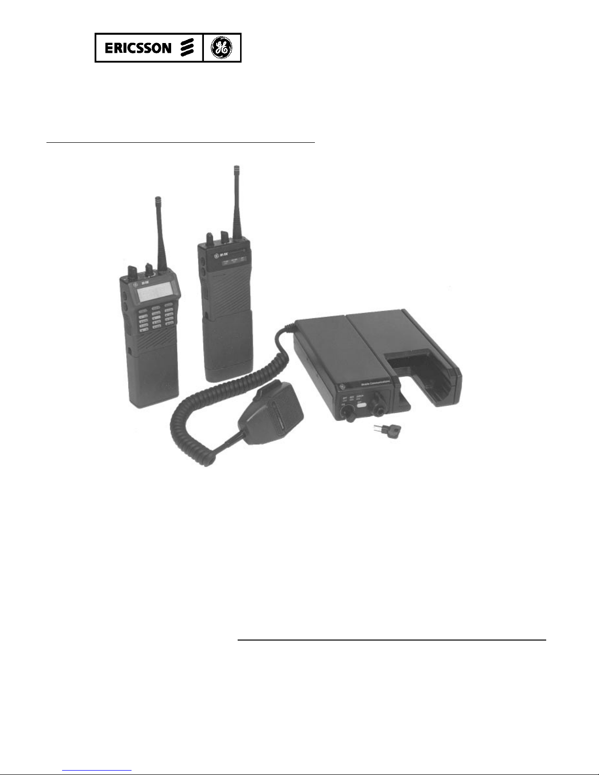
Installation/
Operator’s Manual
Mobile Communications
STANDARD M-RK
VEHICULAR CHARGER
344A4616P1
ENHANCED M-RK
VEHICULAR CHARGER
344A4616P2
Page 2

2
TABLE OF CONTENTS
Page
SAFETY INFORMATION......................................................... 3
SAFE DRIVING RECOMMENDATIONS FOR USERS
OF MOBILE RADIOS RECOMMMENDED BY AAA..... 5
OPERATING RULES AND REGULATIONS.......................... 5
OPERATING TIPS..................................................................... 6
INTRODUCTION....................................................................... 7
OPERATION.............................................................................. 9
MOBILE CHARGER OPERATION.................................. 9
Standard Vehicular Charger (Repeater Control)
(344A4616P1)................................................................. 9
Enhanced Vehicular Charger (344A4616P2)...................10
FRONT PANEL SWITCHES AND INDICATORS............12
Standard Vehicualr Charger (344A4616P1) ....................12
Enhanced Vehicular Charger (344A4616P2)...................12
BATTERY CHARGER DETAILS......................................15
INSTALLATION........................................................................16
UNPACKING AND CHECKING THE EQUIPMENT......16
PLANNING THE INSTALLATION...................................17
TOOLS REQUIRED............................................................18
SETTING THE DIP SWITCHES........................................18
Copyright© February 1994, Ericsson GE Mobile Communications Inc.
Figure 7 - P2 Enhanced Charger Interconnection Diagram Using
Page 3

3
TABLE OF CONTENTS (Continued)
Page
OPERATIONAL MODES - DIP SWITCH CONTROL
STD/REPEATER ..........................................................19
OPERATIONAL MODES - DIP SWITCH CONTROL
ENHANCED CHARGER............................................. 19
MOUNTING THE UNIT ....................................................21
INTERCONNECT CABLE.................................................23
Power Leads....................................................................24
Speaker Leads (For P2 Enhanced Vehicular
Charger Only).................................................................24
Antenna Connections (For P2 Enhanced Vehicular
Charger Only).................................................................24
Other Connections .........................................................24
SAFETY INFORMATION
The operator of any mobile radio should be aware of certain
hazards common to the operation of vehicular radio transmissions. A
list of several possible hazards is given:
1. Explosive Atmospheres - Just as it is dangerous to fuel a vehicle
with the motor running, similar hazards exist when operating a
mobile radio, be sure to turn the radio off while fueling the
vehicle. Do not carry containers of fuel in the trunk of the vehicle
if the radio is mounted in the trunk.
2. Interference to Vehicular Electronics Systems - Electronic fuel
injection systems, electronic anti-skid braking systems, electronic
cruise control systems, etc., are typical electronic systems that may
malfunction due to the lack of protection from radio frequency
energy present when transmitting. If the vehicle contains such
equipment, consult the dealer and enlist his aid in determining the
expected performance of electronic circuits when the radio is
transmitting.
Page 4

4
3. Dynamite Blasting Caps - Dynamite blasting caps may be caused
to explode by operating a radio within 500 feet of the blasting
caps. Always obey the "Turn Off Two-Way Radios" signs
posted where dynamite is being used.
When transporting blasting caps in your vehicle:
a. Carry the blasting caps in a closed metal box with a soft
lining.
b. Leave the radio OFF whenever the blasting caps are
being put into or removed from the vehicle.
4. Radio Frequency Energy - To prevent burns or related physical
injury from radio frequency energy, do not operate the transmitter
when anyone outside of the vehicle is within two feet of the
antenna.
5. Liquefied Petroleum (LP) Gas Powered Vehicles - Mobile radio
installations in vehicles powered by liquefied petroleum gas with
the LP gas container in the trunk or other sealed-off space within
the interior of the vehicle must conform to the National Fire
Protection Association standard (NFPA) 58 requiring:
a. The space containing the radio equipment shall be
isolated by a seal from the space containing the LP gas
container and its fittings.
b. Outside filling connections shall be used for the LP gas
container.
c. The LP gas container shall be vented to the outside of the
vehicle.
CAUTION
Before jump starting or changing the vehicle battery, it is strongly
suggested that the 3A fuse located in the Yellow lead (IGN A+) be
removed. This will insure that the radio is protected from damage
during the battery charging process. Replace fuse when charging is
completed.
Figure 5 - Interconnection Drawing For P2 Charger Using
Page 5

5
SAFE DRIVING RECOMMENDATIONS FOR
USERS OF MOBILE RADIOS RECOMMENDED BY
AAA
• Read the literature on the safe operation of the radio.
• Keep both hands on the steering wheel and the microphone in
its hanger whenever the vehicle is in motion.
• Place calls only when vehicle is stopped.
• When talking from a moving vehicle is unavoidable, drive in
the slower lane. Keep conversations brief.
• If a conversation requires taking notes or complex thought,
stop the vehicle in a safe place and continue the call.
• Whenever using a mobile radio exercise caution.
OPERATING RULES AND REGULATIONS
Two-way FM radio systems must be operated in accordance with
the rules and regulations of the Federal Communications Commission
(FCC). As an operator of two-way radio equipment, you must be
thoroughly familiar with the rules that apply to your particular type of
radio operation. Following these rules helps eliminate confusion,
assures the most efficient use of the existing radio channels, and
results in a smoothly functioning radio network.
When using your two-way radio, remember these rules:
1. It is a violation of FCC rules to interrupt any distress or
emergency message. As your radio operates in much the same
way as a telephone "party line", always listen to make sure
that the channel is clear before transmitting. Emergency calls
havepriority over all other messages. If someone is sending an
emergency message - such as reporting a fire or asking for
help in an accident - KEEP OFF THE AIR!
2. The use of profane or obscene language is prohibited by
Federal law.
Page 6

6
3. It is against the law to send false call letters or false distress
or emergency messages. The FCC requires that you keep
conversations brief and confine them to business. To save
time, use coded messages whenever possible.
4. Using your radio to send personal messages (except in an
emergency) is a violation of FCC rules. You may send only
those messages that are essential for the operation of your
business.
5. I t is against Federal law to repeat or otherwise make known
anything you overhear on your radio. Conversations between
others sharing your channel must be regarded as confidential.
6. The FCC requires that you identify yourself a t certain specific
times by means of your call letters. Refer to the rules that
apply to your particular type of operation for the proper
procedure.
7. No changes or adjustments shall be made to the equipment
except by an authorized or certified electronic technician.
IMPORTANT
OPERATING TIPS
The following conditions tend to reduce the effective range of two-
way radios and should be avoided whenever possible:
• Operating the radio in areas of low terrain, or while under
power lines or bridges.
• Obstructions such as mountains and buildings.
In areas where transmission or reception is poor, some
improvement may be obtained by insuring that the antenna is vertical.
Under U.S. law, operation of an unlicensed radio transmitter
within the jurisdiction of the United States may be punishable by
a fine of up to $10,000, imprisonment for up to two years, or
both!
INTERCONNECT CABLE
Power Leads
The power leads of the interconnect cable supplied with the
charger must be connected to the vehicle's battery (for the Part 2 and
ORION Control Head chargers). The vehicle must have a negative-
ground electrical system. Power leads are approximately 8 feet in
length. The YELLOW (positive) lead includes a fuse holder and 5-
ampere fuse located near the battery end.
The charger can be wired to an unswitched power source so the
charger can operate when the vehicle's ignition switch is turned off.
However, if desired, the charger can be controlled by a switched power
source by running a lead to the ignition switch power (be sure to
connect this lead behind the vehicle's fuse box so that the vehicle's fuse
protection is used). The other end of this lead must be connected to the
DB-25 connector at pin 10. The power source must have adequate
current supply capability. If the switched power connections are used
the Charger's DIP switch settings must be changed as shown under,
"SETTING THE DIP SWITCHES”, to Enable Ignition A+.
If the charger is wired directly to the vehicle's battery it will be
necessary to route the power leads through the vehicle's firewall. If a n
existing hole is not conveniently located in the firewall, drill a small
hole and install an appropriately sized rubber grommet before routing
the leads through the firewall. This grommet is required to prevent
lead chaffing. Additional grommets may be required if the leads must
pass through shields or guards in the engine compartment between th e
firewall and battery. Route the leads away from high heat sources in
the engine compartment that may cause lead damage and introduce a
fire hazard. In addition, the leads should not be routed near noise
sources such as electronic ignition modules or cruise control modules.
Use appropriate lacing techniques to secure the leads away from all
moving parts.
Connect the BLACK lead to the negative power source ("NEG" or
"-" battery post) and connect the YELLOW lead to the positive power
source ("POS" or "+" battery post).
Page 7

7
Moving a few yards in another direction or moving to a higher
elevation may also improve communication.
INTRODUCTION
The Ericsson GE M-RK Standard Vehicular Charger
(344A4616P1) and Enhanced Vehicular Charger (344A4616P2) units
can be used with both the M-RK I and M-RK II Personal radios with
swivel mount or belt clips attached. Any of the four batteries listed
below can be used with the MR-K I, or II radios and these chargers.
19A149838P1 1200 mAh
19A149838P2 1200 mAh (intrinsically safe)
344A3278P1 1700 mAh
344A3278P2 1700 mAh (intrinsically safe)
A vehicular charger enhances the operational versatility of an MRK radio in the mobile environment. See Table 1 for the features of
each unit.
The Standard Vehicular Charger (Repeater) (344A4616P1) is
designed to provide recharge of M-RK radio batteries without
provision for operation while in the charger. With this model charger,
M-RK radio operation is only possible outside of the charger. The
vehicular repeater is automatically disabled when the M-RK radio is
placed in the Charger and the unit performs the charging function.
The Charger has an ON/OFF repeater enable switch for operation with
the M-RK radio outside the Charger. Both fast and slow charge rates
are built into the charger that operate automatically based upon battery
pack voltage and temperature.
The Enhanced Vehicular Charger (344A4616P2) simultaneously
charges the M-RK's battery pack while allowing the radio to operate as
a mobile radio with an external antenna, speaker, and microphone.
The same fast and slow charge rates are provided (as in Part 1) that
depend upon the battery pack voltage and temperature conditions.
Mobile radio operation is accomplished through the use of an external
speaker, external microphone and external antenna connections. A
speaker amplifier in the charger unit provides u p to 10 watts of audio
output power to an external speaker. A volume control o n the charger
Page 8

8
provides audio level adjustment for the external speaker. The MRK's
volume setting does not affect the audio level of the charger.
With the Enhanced charger, operation of the M-RK radio while
inserted in the charger is possible even though the NICAD battery is
completely discharged.
Table 1 gives feature comparisons for the two vehicular chargers
and Figure 1 shows the Front Panels of both units.
TABLE 1 - FEATURES
FEATURE
STANDARD ENHANCED
Fast Charge Yes Yes
Slow Charge Yes Yes
Dead Battery Pack Operation No Yes
Charge and Ready Indicator Lights Yes Yes
Transmitter Enabled Indicator
Light
No Yes
Vehicular Repeater Enabled
Indicator Light
Yes No
10-Watt External Speaker
Amplifier with Volume Control
No Yes
External Microphone Control No Yes
External Antenna Connector No Yes
3. REMOTE CONTROL OPERATION
The enhanced charger can be operated under remote control of an
ORION control head. For interconnection details see the
applicable maintenance manual (LBI). When operating in the
remote control mode the following functions must be sent using
the dip switches.
IGNITION A+ Inhibited SW3-1 Set to "ON"
FRONT OPTION Inhibited SW3-4 Set to "OFF"
SWITCH
REMOTE Enabled SW3-7 Set to "ON"
CONTROL
SWITCH SW5 Enabled SW5-1 Set to "ON"
MOUNTING THE UNIT
The unit can be mounted on the underside of the dash panel of the
vehicle or in a DIN-size opening in the dash panel. It can also be
mounted to the vehicle's floor "hump" using an optional hump-mount
bracket. The following instructions outline the mechanical installation
details.
1. Select a mounting location. Confirm that the location is
appropriate as outlined in the section entitled
"PLANNING THE INSTALLATION".
2. Using the mounting bracket as a template, mark six (6) mounting
screw hole locations on the mounting surface (dash panel, floor
board, etc).
3. Using a No. 28 drill bit, drill holes i n the mounting surface at the
marked locations.
Page 9

9
Figure 1- -Standard and Enhanced Vehicular Chargers
OPERATION
MOBILE CHARGER OPERATION
Operation of the Charger is possible in three configurations. (1)
As a standard vehicular charger and repeater control, (2) as and
Enhanced Charger providing added operational features, and (3) as an
Ehanced Charger operating via the ORION Control Head. For
operation in configuration (3) see the applicable Operator's Manual.
Standard Vehicular Charger (with Repeater) (344A4616P1)
Operation of the chargers is automatic when the M-RK personal
radio is inserted. The radio is inserted i n the charger when the battery
needs recharging. With the charger standard model, no operation of
the radio is possible while the radio battery is charging. Operation of
the radio with this model charger is done after the personal radio
battery is charged, it is removed from the charger and (normally) is
taken outside the vehicle and operated via a repeater radio. Note that
the vehicular repeater is automatically disabled when the radio is in
STANDARD/REPEATER CONTROL
ENHANCED
Page 10

10
the charger unit for recharging. Charging commences immediately,
whether or not the UDC INTERFACE is engaged.
The radio is normally operated via a vehicular repeater with this
charger to improve communication range. For this operation, the
operator takes the following steps:
1. Remove the radio from the charger.
2. Turn on the radio.
3. Turn on the vehicular repeater using the small knob at the lower
left corner of the radio front panel. The RPT indicator light, in the
upper left corner of the front panel, glows AMBER when the
repeater is ON.
4. After monitoring the channel for activity and finding it free, press
PTT and make your call.
Enhanced Vehicular Charger (344A4616P2)
The Enhanced Vehicular Charger (344A4616P2) allows the
M-RK Personal radio to operate in the charger while the battery pack
is simultaneously being charged. The procedure is as follows:
1. Before attempting to insert the M-RK personal radio in the
charger, verify that the ROTARY LATCH KNOB is in the
released position. If not, unlock if necessary and press down on
the RELEASE BUTTON until the knob snaps to the released
position.
NEVER insert nor remove the radio from the charger
unit by pulling on the antenna, or using it as a handle,
as this may damage the antenna.
NOTE
1-POSITION SWITCH
VEH REPEATER
ENHANCED VEH
* SW5-1 Not inclued in 344A4616P1 (all revision)
Included in 344A4616P2, Rev A (Not included in Rev. - )
OPERATIONAL MODES - DIP SWITCH CONTROL
STD/REPEATER
1. IGNITION A+ CONTROL
To control the power to the charger by the ignition switch, a
control wire must be connected from the rear DB-25 connector,
Pin 10 to the ignition switch.
Connect this added wire to the ignition "ON" sense point
(preferably an "accessory" point on the fuse panel that is
switched on when the ignition switch is in the accessory position
and in the "RUN" position).
The ignition control logic inside the charger must be enabled by
setting the following SW3 dip switch positions:
2. FRONT PANEL CONTROL
This function is not applicable in the STD/REPEATER.
3. REMOTE CONTROL OPERATION
This function is not applicable in the STD/REPEATER.
Page 11

11
2. Insert the M-RK Personal Radio into the charger by sliding it
down into the slot. The radio should be inserted so that the front
of it faces the top of the charger unit (as shown in Figure 2).
When fully inserted, the radio extends approximately 1/8" inch
above the front of the charger. The fast charge begins immediately
and the yellow charge indicator is illuminated.
4. Engage the UDC INTERFACE connector by turning the
ROTARY LATCH KNOB approximately 1/4 turn in a clockwise
direction until it clicks into the latched position. This onnects the
M-RK radio to the Vehicular Charger's audio circuits and to the
external antenna. The radio cannot be removed from this position
until the UDC INTERFACE connector is unlatched using the
RELEASE BUTTON in the center of the ROTARY LATCH
KNOB.
Figure 2 - Charger with M-RK II Personal Radio Inserted
Page 12

12
UDC Released
UDC Engaged
Figure 3 - UDC Connector Rotary Latch Knob
5. If desired, the radio can now be locked into the charger to prevent
unauthorized removal. To lock the radio in the charger, insert the
key in the hole in the RELEASE BUTTON, turn in a clockwise
direction until it stops and remove the key. To unlock the radio,
insert the key and turn it in a counterclockwise direction.
6. Turn the radio on by rotating its power on-off/VOLUME knob
clockwise out of the detent (OFF) position.
7. The charger and radio are now set for mobile operation. Use the
charger's VOLUME CONTROL KNOB to adjust the external
speaker volume level and use the MICROPHONE's PTT button to
transmit. The red TRANSMIT INDICATOR lights when the
radio is transmitting.
8. When removal of the M-RK is necessary, disengage the UDC
INTERFACE by pressing down o n the RELEASE BUTTON until
the ROTARY LATCH KNOB snaps to the released position. (If
the Rotary Latch Knob is locked, it must be unlocked before it will
snap release. See step 5. above.) Grip the radio on its sides and
pull it out of the charger.
NOTE
NEVER insert nor remove the radio from the charger unit by
pulling on the antenna, or using it as a handle, as this may
damage the antenna.
¨
¨
PLANNING THE INSTALLATION
The installation of the Standard Vehicular Charger or the
Enhanced Vehicular Charger should be carefully planned, before work
actually begins.
Mechanical installation guidelines include mounting the unit:
• in a location that is safe for the operator and any passengers
• in a location that is convenient for the operator to use
• in a location that allows the operator to easily slip the radio
• in a location that allows easy operator access to the external
• in a location that is protected from water damage
• in a location that is out-of-the-way of auto mechanics
• in a location that is out-of-the-way of any passengers
• in a location that provides adequate clearance for attaching
• so it can be easily removed for cleaning and servicing
• securely so that it is not likely to break loose in the event of a
Page 13

13
FRONT PANEL SWITCHES AND INDICATORS
Standard Vehicular Charger (344A4616P1)
This front panel contains three (3) indicator lights; RPT,
RDY, and CHRG, an ON/OFF switch for the Repeater Radio and
the UDC ROTARY LATCH KNOB.
(1) Indicator Lights -
RPT (Amber) - Lights if the Repeater Radio is
enabled.
RDY (Green) - Lights if the Battery is 90 to 100
percent charged and the charger
reverts to "trickle" charge.
CHRG (Yellow) - Lights when radio is first inserted in
the charger. Indicates Radio is being
"fast" charged.
(2) Repeater ON/OFF switch -
Turning this switch ON any time the M-RK personal
radio is out of the charger enables the repeater radio and
lights the Amber Indicator light.
(3) UDC Rotary Latch Knob -
This knob latches the M-RK personal radio in the
charger and connects the UDC connector to all circuits
within the charger to allow radio operation as a mobile
radio. It should always be latched when the radio is in
the charger and the vehicle is moving.
Enhanced Vehicular Charger (344A4616P2)
This front panel contains three (3) indicator lights; TX, RDY,
and CHRG, an ON/OFF volume control switch for operation of
the M-RK Personal radio as a mobile radio, an Option pushbutton,
and the UDC ROTARY LATCH KNOB.
(1) Indicator Lights -
TX (Red) - Lights if the M-RK transmitter is
active.
RDY (Green) - Lights if the Battery is 90 to 100
percent charged and the charger
reverts to "trickle" charge.
Page 14

14
CHRG (Yellow) - Lights when radio is first inserted in
the charger. Indicates Radio is being
"fast" charged.
(2) ON/OFF Volume Control Switch -
This switch powers the radio for operation as a mobile.
Check to assure that the UDC LATCH KNOB is in the
"engaged" position.
(3) Option Pushbutton -
This button can be programmed for many functions, but
factory programming causes the same action as the MRK "Clear" function. (See the M-RK Operator's Manual
LBI-38732 or LBI-38733).
(4) UDC Rotary Latch Knob -
This knob latches the M-RK personal radio in the
charger and connects the UDC connector to all circuits
within the charger to allow M-RK radio operation as a
mobile radio. It should always be latched when the radio
is in the charger and the vehicle is moving.
BATTERY CHARGER DETAILS
To maximize nickel cadmium battery life, the M-RK vehicular
chargers are designed with automatic controls which limit the rapid
charging of M-RK batteries if the internal battery temperature is
below 0° C (+32° F) or above +45° C (+113° F). The charger
indicates this high or low internal temperature condition by a yellow
LED which blinks at a slow rate.
If a slow blinking, yellow LED is observed, the operator must
wait until the internal battery temperature stabilizes within the
allowable range before restarting the charging procedure by
removing and re-inserting the radio into the charger.
In a vehicular application, with either high ambient temperature
inside or outside of the vehicle, the automatic charging control will
often prevent rapid charging or limit the time of rapid charging.
In other situations, where the operator inserts and removes the
radio many times during a short period of time, the automatic control
will sense a high internal battery temperature (due to start-up rapid
charging of the battery) and will prevent further rapid charging of
the battery until the internal temperature of the battery stabilizes
within the acceptable range.
When the M-RK radio (with its battery pack) is placed in the
charger, the radio's battery pack is charged. The fast or "rapid" charge
feature, normally is applied immediately, and is controlled by the
microprocessor circuits within the charger. The following details apply
to the battery charge feature:
• Normally, when initially placed in the charger, the battery pack is
fast charged and the yellow charge indicator glows continuously
until it is near a full charge (between 90% and 100% full charge).
At this time the charger switches to a slow or "trickle" charge rate
and completes the charge. During the "trickle" charge the green
ready indicator is illuminated.
Page 15

15
BATTERY CHARGER DETAILS
NOTE
To maximize nickel cadmium battery life, the M-RK vehicular
chargers are designed with automatic controls which limit the rapid
charging of M-RK batteries if the internal battery temperature is
below 0° C (+32° F) or above +45° C (+113° F). The charger
indicates this high or low internal temperature condition by a yellow
LED which blinks at a slow rate.
If a slow blinking, yellow LED is observed, the operator must
wait until the internal battery temperature stabilizes within the
allowable range before restarting the charging procedure by
removing and re-inserting the radio into the charger.
In a vehicular application, with either high ambient temperature
inside or outside of the vehicle, the automatic charging control will
often prevent rapid charging or limit the time of rapid charging.
In other situations, where the operator inserts and removes the
radio many times during a short period of time, the automatic control
will sense a high internal battery temperature (due to start-up rapid
charging of the battery) and will prevent further rapid charging of
the battery until the internal temperature of the battery stabilizes
within the acceptable range.
When the M-RK radio (with its battery pack) is placed in the
charger, the radio's battery pack is charged. The fast or "rapid" charge
feature, normally is applied immediately, and is controlled by the
microprocessor circuits within the charger. The following details apply
to the battery charge feature:
• Normally, when initially placed in the charger, the battery pack is
fast charged and the yellow charge indicator glows continuously
until it is near a full charge (between 90% and 100% full charge).
At this time the charger switches to a slow or "trickle" charge rate
and completes the charge. During the "trickle" charge the green
ready indicator is illuminated.
Page 16

16
•
The yellow CHARGE INDICATOR lights when the unit is fast
charging.
•
If the CHARGE INDICATOR flashes, the battery is not being fast
charged. Several factors may cause this to occur. These include,
dirty battery pack contacts, an extremely hot or cold battery pack,
or a defective battery pack.
•
The yellow CHARGE INDICATOR turns off and the green
READY INDICATOR turns on when the unit has completed the
fast charge and the "trickle" charge commences.
•
If the battery pack is completely dead, M-RK mobile mode
operation can continue normally (with a P2 Enhanced Charger
unit). To do this, insert the radio (with the dead battery pack) into
the charger and engage the UDC INTERFACE for operation.
•
Normal engagement of the UDC INTERFACE is not necessary for
battery charge operation, but is required to operate an M-RK
Personal in the enhanced vehicular charger during the charging
cycle. The UDC INTERFACE ROTARY LATCH KNOB should
also be in the "engaged" position whenever the vehicle is moving,
for both the standard and enhanced models, to firmly hold the
radio in the charger in case of an accident.
INSTALLATION
UNPACKING AND CHECKING THE EQUIPMENT
Before starting the installation, carefully unpack the equipment i n
the shipping container and identify each item as listed below. If any
damage has occurred to the equipment during shipment, file a claim
with the carrier immediately.
¨
M-RK Standard Vehicular Charger 344A4616P1
or
¨
M-RK Enhanced Vehicular Charger 344A4616P2
¨
Interconnect Cable 344A4616P10
(For Vehicular Repeater Control operation, optional power
cable 344A4616P12 must be used)
FRONT PANEL SWITCHES AND INDICATORS
Standard Vehicular Charger (344A4616P1)
RDY, and CHRG, an ON/OFF switch for the Repeater Radio and
the UDC ROTARY LATCH KNOB.
Enhanced Vehicular Charger (344A4616P2)
and CHRG, an ON/OFF volume control switch for operation of
the M-RK Personal radio as a mobile radio, an Option pushbutton,
and the UDC ROTARY LATCH KNOB.
Page 17

17
¨
Mounting Bracket and Mounting Hardware 344A4616P11
(mounting hardware includes four machine screws, four lock
washers, six self-tapping screws and one cable tie)
¨
Operator's/Installation Manual LBI-38935 (this manual)
PLANNING THE INSTALLATION
The installation of the Standard Vehicular Charger or the
Enhanced Vehicular Charger should be carefully planned, before work
actually begins.
Mechanical installation guidelines include mounting the unit:
• in a location that is safe for the operator and any passengers
in the vehicle
• in a location that is convenient for the operator to use
• in a location that allows the operator to easily slip the radio
into and out of the unit
• in a location that allows easy operator access to the external
microphone or other options that can be attached (Enhanced
Vehicular Charger unit only)
• in a location that is protected from water damage
• in a location that is out-of-the-way of auto mechanics
• in a location that is out-of-the-way of any passengers
• in a location that provides adequate clearance for attaching
cables and connectors
• so it can be easily removed for cleaning and servicing
• securely so that it is not likely to break loose in the event of a
collision
Page 18

18
Electrical installation guidelines include:
• wiring the unit in accordance with the diagrams and
instructions provided in this manual
• observing quality wiring techniques
Ericsson GE recommends that the unit be installed by one of the
many authorized General Electric Service Stations located throughout
the United States. Personnel at these centers are experienced in
installations of this type of equipment and can provide a safe, neat and
functional installation.
TOOLS REQUIRED
• Electric Drill
• No. 28 Drill Bit
• Hole Saw
• Phillips and Flat-Blade Screwdrivers
• POZIDRIV Driver
SETTING THE DIP SWITCHES
A DIP (Dual-Inline-Package) switch is located inside the unit that
allows it to be configured for several different operational modes.
DIP SWITCH POSITION FACTORY SETTINGS
SW 3
(7-POSITION
SWITCH)
1
234567
P1
VEH REPEATER
CHARGER
ON OFF ON OFF OFF OFF OFF
P2
ENHANCED VEH
CHARGER
ON OFF ON ON ON OFF OFF
2. Insert the M-RK Personal Radio into the charger by sliding it
down into the slot. The radio should be inserted so that the front
of it faces the top of the charger unit (as shown in Figure 2).
When fully inserted, the radio extends approximately 1/8" inch
above the front of the charger. The fast charge begins immediately
and the yellow charge indicator is illuminated.
4. Engage the UDC INTERFACE connector by turning the
ROTARY LATCH KNOB approximately 1/4 turn in a clockwise
direction until it clicks into the latched position. This onnects the
M-RK radio to the Vehicular Charger's audio circuits and to the
external antenna. The radio cannot be removed from this position
until the UDC INTERFACE connector is unlatched using the
RELEASE BUTTON in the center of the ROTARY LATCH
KNOB.
Figure 2 - Charger with M-RK II Personal Radio Inserted
Page 19

19
SW5
1-POSITION SWITCH
1
P1
VEH REPEATER
CHARGER
N/A *
P2
ENHANCED VEH
CHARGER
ON
* SW5-1 Not inclued in 344A4616P1 (all revision)
Included in 344A4616P2, Rev A (Not included in Rev. - )
OPERATIONAL MODES - DIP SWITCH CONTROL
STD/REPEATER
1. IGNITION A+ CONTROL
To control the power to the charger by the ignition switch, a
control wire must be connected from the rear DB-25 connector,
Pin 10 to the ignition switch.
Connect this added wire to the ignition "ON" sense point
(preferably an "accessory" point on the fuse panel that is
switched on when the ignition switch is in the accessory position
and in the "RUN" position).
The ignition control logic inside the charger must be enabled by
setting the following SW3 dip switch positions:
SW3-1 Set to "OFF"
SW3-2 Set to "ON"
2. FRONT PANEL CONTROL
This function is not applicable in the STD/REPEATER.
3. REMOTE CONTROL OPERATION
This function is not applicable in the STD/REPEATER.
Page 20

20
OPERATIONAL MODES-DIP SWITCH CONTROL
ENHANCED CHARGER
1. IGNITION A+ CONTROL
To control the power to the charger by the ignition switch, a
control wire must be connected from the rear DB-25 connector,
Pin 10 to the ignition switch.
Connect this added wire to the ignition "ON" sense point
(preferably an "accessory" point on the fuse panel that is
switched on when the ignition switch is in the accessory position
and in the "RUN" positions:
The ignition control logic inside the charger must be enabled by
setting the following SW3 dip switch positions:
SW3-1 Set to "ON"
SW3-6 Set to "OFF"
SW5-1 Set to "OFF"
2. DISPLAY INVERT CONTROL
To M-RK II display may either be placed in the normal mode or
the inverted mode by setting the following SW3 dip switch
positions:
DISPLAY NORMAL SW3-5 Set to "ON"
SW3-6 Set to "OFF"
SW3-7 Set to "OFF"
SW5-1 Set to "OFF"
DISPLAY INVERTED SW3-5 Set to "OFF"
SW3-6 Set to "ON"
SW3-7 Set to "OFF"
SW5-1 Set to "OFF"
Figure 1- -Standard and Enhanced Vehicular Chargers
MOBILE CHARGER OPERATION
Operation of the Charger is possible in three configurations. (1)
As a standard vehicular charger and repeater control, (2) as and
Enhanced Charger providing added operational features, and (3) as an
Ehanced Charger operating via the ORION Control Head. For
operation in configuration (3) see the applicable Operator's Manual.
Standard Vehicular Charger (with Repeater) (344A4616P1)
Operation of the chargers is automatic when the M-RK personal
radio is inserted. The radio is inserted i n the charger when the battery
needs recharging. With the charger standard model, no operation of
the radio is possible while the radio battery is charging. Operation of
the radio with this model charger is done after the personal radio
battery is charged, it is removed from the charger and (normally) is
taken outside the vehicle and operated via a repeater radio. Note that
the vehicular repeater is automatically disabled when the radio is in
STANDARD/REPEATER CONTROL
ENHANCED
Page 21

21
3. REMOTE CONTROL OPERATION
The enhanced charger can be operated under remote control of an
ORION control head. For interconnection details see the
applicable maintenance manual (LBI). When operating in the
remote control mode the following functions must be sent using
the dip switches.
IGNITION A+ Inhibited SW3-1 Set to "ON"
SW3-2 Set to "OFF"
FRONT OPTION Inhibited SW3-4 Set to "OFF"
SWITCH
REMOTE Enabled SW3-7 Set to "ON"
CONTROL
SWITCH SW5 Enabled SW5-1 Set to "ON"
MOUNTING THE UNIT
The unit can be mounted on the underside of the dash panel of the
vehicle or in a DIN-size opening in the dash panel. It can also be
mounted to the vehicle's floor "hump" using an optional hump-mount
bracket. The following instructions outline the mechanical installation
details.
1. Select a mounting location. Confirm that the location is
appropriate as outlined in the section entitled
"PLANNING THE INSTALLATION".
2. Using the mounting bracket as a template, mark six (6) mounting
screw hole locations on the mounting surface (dash panel, floor
board, etc).
3. Using a No. 28 drill bit, drill holes i n the mounting surface at the
marked locations.
Page 22

22
Before drilling any hole, verify that no damage will occur to any
vital part of the vehicle. Fuel tanks, transmission housings, fuel
lines, brake lines and wiring harnesses are typical items that can
be damaged when a drill bit or screw penetrates through the
mounting surface.
If mounting on a surface covered with carpet, punch holes in the
carpet with a small punch, make a small incision in the carpet,
insert a short piece of metal tubing and then drill through the
tubing. This prevents twisting the carpet with the drill flukes.
4. Using the six (6) self-tapping screws, secure the mounting bracket
to the mounting surface.
5. Using the four (4) machine screws and lock washers, secure the
unit to the mounting bracket. It can be fastened in any of three (3)
different positions: parallel to the mounting surface or tilted ±20
degrees from the parallel position. See Figure 4.
Figure 4 - Mounting the Charger
CAUTION
NOTE
Moving a few yards in another direction or moving to a higher
elevation may also improve communication.
The Ericsson GE M-RK Standard Vehicular Charger
(344A4616P1) and Enhanced Vehicular Charger (344A4616P2) units
can be used with both the M-RK I and M-RK II Personal radios with
swivel mount or belt clips attached. Any of the four batteries listed
below can be used with the MR-K I, or II radios and these chargers.
A vehicular charger enhances the operational versatility of an M-
RK radio in the mobile environment. See Table 1 for the features of
each unit.
The Standard Vehicular Charger (Repeater) (344A4616P1) is
designed to provide recharge of M-RK radio batteries without
provision for operation while in the charger. With this model charger,
M-RK radio operation is only possible outside of the charger. The
vehicular repeater is automatically disabled when the M-RK radio is
placed in the Charger and the unit performs the charging function.
The Charger has an ON/OFF repeater enable switch for operation with
the M-RK radio outside the Charger. Both fast and slow charge rates
are built into the charger that operate automatically based upon battery
pack voltage and temperature.
The Enhanced Vehicular Charger (344A4616P2) simultaneously
charges the M-RK's battery pack while allowing the radio to operate as
a mobile radio with an external antenna, speaker, and microphone.
The same fast and slow charge rates are provided (as in Part 1) that
depend upon the battery pack voltage and temperature conditions.
Mobile radio operation is accomplished through the use of an external
speaker, external microphone and external antenna connections. A
speaker amplifier in the charger unit provides u p to 10 watts of audio
output power to an external speaker. A volume control o n the charger
Page 23

23
INTERCONNECT CABLE
Power Leads
The power leads of the interconnect cable supplied with the
charger must be connected to the vehicle's battery (for the Part 2 and
ORION Control Head chargers). The vehicle must have a negativeground electrical system. Power leads are approximately 8 feet in
length. The YELLOW (positive) lead includes a fuse holder and 5ampere fuse located near the battery end.
The charger can be wired to an unswitched power source so the
charger can operate when the vehicle's ignition switch is turned off.
However, if desired, the charger can be controlled by a switched power
source by running a lead to the ignition switch power (be sure to
connect this lead behind the vehicle's fuse box so that the vehicle's fuse
protection is used). The other end of this lead must be connected to the
DB-25 connector at pin 10. The power source must have adequate
current supply capability. If the switched power connections are used
the Charger's DIP switch settings must be changed as shown under,
"SETTING THE DIP SWITCHES”, to Enable Ignition A+.
If the charger is wired directly to the vehicle's battery it will be
necessary to route the power leads through the vehicle's firewall. If a n
existing hole is not conveniently located in the firewall, drill a small
hole and install an appropriately sized rubber grommet before routing
the leads through the firewall. This grommet is required to prevent
lead chaffing. Additional grommets may be required if the leads must
pass through shields or guards in the engine compartment between th e
firewall and battery. Route the leads away from high heat sources in
the engine compartment that may cause lead damage and introduce a
fire hazard. In addition, the leads should not be routed near noise
sources such as electronic ignition modules or cruise control modules.
Use appropriate lacing techniques to secure the leads away from all
moving parts.
Connect the BLACK lead to the negative power source ("NEG" or
"-" battery post) and connect the YELLOW lead to the positive power
source ("POS" or "+" battery post).
Page 24

24
Speaker Leads (For P2 Enhanced Vehicular Charger Only)
Other leads on the interconnect cable include the external speaker
leads that are approximately 18 inches in length. Route and connect
these leads to the external speaker. Since the charger has differentialtype speaker amplifier output lines, use speaker option 19A149590P1,
or do not ground either speaker lead if another speaker is used. The
speaker must be rated for at least 10 watts and a 4-ohm impedance is
recommended.
The external speaker normally supplied with the charger is option
H2LS1F (19A149590P1). This speaker has a 20-watt rating and a 4ohm impedance.
Antenna Connection (For P2 Enhanced Vehicular Charger Only)
The TNC connector at the back of the Enhanced Vehicular
Charger must be connected to the external antenna. For optimum
performance, the antenna should be installed in accordance with the
installation instructions provided with the antenna package.
Other Connections
See the Interconnection Diagrams in the following pages for
specific details on other connections that may be required. Standard
cable wiring is shown in these diagrams for the Part 2 and ORION
Control Head connections that include power connections. For the Part
1 Charger, power is supplied via the Repeater as shown by
identification of leads in that connection.
SAFE DRIVING RECOMMENDATIONS FOR
USERS OF MOBILE RADIOS RECOMMENDED BY
AAA
• Read the literature on the safe operation of the radio.
• Keep both hands on the steering wheel and the microphone in
• Place calls only when vehicle is stopped.
• When talking from a moving vehicle is unavoidable, drive in
• If a conversation requires taking notes or complex thought,
• Whenever using a mobile radio exercise caution.
OPERATING RULES AND REGULATIONS
Two-way FM radio systems must be operated in accordance with
the rules and regulations of the Federal Communications Commission
(FCC). As an operator of two-way radio equipment, you must be
thoroughly familiar with the rules that apply to your particular type of
radio operation. Following these rules helps eliminate confusion,
assures the most efficient use of the existing radio channels, and
results in a smoothly functioning radio network.
When using your two-way radio, remember these rules:
1. It is a violation of FCC rules to interrupt any distress or
2. The use of profane or obscene language is prohibited by
Page 25

25
Figure 5 - Interconnection Drawing For P2 Charger Using
344A4616P10 Cable
Page 26

26
Figure 6 - P1 STD/Repeater Interconnection Diagram Using
344A4616P12 Cable
OPERATIONAL MODES - DIP SWITCH CONTROL
OPERATIONAL MODES - DIP SWITCH CONTROL
MOUNTING THE UNIT ....................................................21
INTERCONNECT CABLE.................................................23
The operator of any mobile radio should be aware of certain
hazards common to the operation of vehicular radio transmissions. A
list of several possible hazards is given:
1. Explosive Atmospheres - Just as it is dangerous to fuel a vehicle
with the motor running, similar hazards exist when operating a
mobile radio, be sure to turn the radio off while fueling the
vehicle. Do not carry containers of fuel i n the trunk of the vehicle
if the radio is mounted in the trunk.
2. Interference to Vehicular Electronics Systems - Electronic fuel
injection systems, electronic anti-skid braking systems, electronic
cruise control systems, etc., are typical electronic systems that may
malfunction due to the lack of protection from radio frequency
energy present when transmitting. If the vehicle contains such
equipment, consult the dealer and enlist his aid in determining the
expected performance of electronic circuits when the radio is
transmitting.
Page 27

27
Figure 7 - P2 Enhanced Charger Interconnection Diagram Using
Optional ORION Control Head Cable
Page 28

28
Ericsson GE Mobile Communications Inc.
Mountain View Road • Lynchburg, Virginia 24502
Printed in U.S.A.
 Loading...