

Ericsson LBI-39060, 344A4189, 19B802884P1-P3 Maintenance Manual
LBI-39060
MAINTENANCE MANUAL
SPEAKER/MICROPHONE
344A4189
EARPHONE
19B802884P1-P3
TABLE OF CONTENTS
Page
DESCRIPTION ............................................................................................................................................................1
MAINTENANCE............................................................................................................................................................2
Back Cover, All Versions..................................................................................................................................2
Front Cover, All Versions .................................................................................................................................2
Cable Assembly, All Versions...........................................................................................................................2
PCB, All Versions.............................................................................................................................................2
Emergency Dome Switch, All Versions ............................................................................................................2
PTT Dome Switch, All Versions.......................................................................................................................3
PTT Button, All Versions..................................................................................................................................3
Thumbscrew, All Versions................................................................................................................................3
DESCRIPTION
The following speaker/microphones and earphone are
covered in this manual:
344A4189P1 M-RK , coiled cord, Ericsson GE logo
344A4189P2 M-RK, straight cord, antenna connector,
Ericsson GE logo
344A4189P3 M-RK, coiled cord, Ericsson logo
344A4189P4 M-RK, straight cord, antenna connector,
Ericsson logo
344A4189P11 M-PA, coiled cord, Ericsson GE logo
344A4189P12 M-PA, straight cord, antenna connector,
Ericsson GE logo
344A4189P13 M-PA, coiled cord, Ericsson logo
344A4189P14 M-PA, straight cord, antenna connector,
Ericsson logo
344A4189P21 PCS, coiled cord, Ericsson GE logo
344A4189P23 PCS, coiled cord, Ericsson logo
19B802884P1 Earphone complete
19B802884P2 Earphone only
19B802884P3 Eartip, earphone adapter, earloop and
cable
The speaker/microphones have a push-to-talk switch
which can be activated from any position. A HI/LO/OFF
switch located on the front permits the user to select a
high or low volume level or when using an earphone, to
mute the speaker in the microphone. A miniature earphone
jack located on the bottom of the case permits the use of
an external earphone.
The Universal Device Connector (UDC) on the end of the
speaker/microphone cable provides the connections to the
radio unit UDC.
The speaker/microphones equipped with an antenna
connector permits an antenna to be connected and used in
place of or in addition to the radio unit antenna.
The following specifications apply:
SPEAKER
Impedance 16 ohms
Power Output 0.5 watts
Audio Response 300 to 3000 Hz
MICROPHONE
Impedance 2K ohms
Frequency Response 100 to 8000 Hz
Sensitivity -35 dBv (94 dB sp<)
Supply Voltage 3 Vdc
1
LBI-39060
EARPHONE
Impedance 2K ohms
Frequency Response 300 to 3000 Hz
ENVIRONMENTAL
Operating -30°C to +60°C
Storage -40°C to +85°C
CABLE ASSEMBLY, ALL VERSIONS
1. Remove back cover by removing four (4) screws
securing housing.
2. Unsolder connections to PCB as indicated in
paragraph "PCB" and remove the PCB.
MAINTENANCE
The following procedures should be followed when
replacing or repairing any of the major replaceable
components such as the back cover, cord, front cover, etc.
It is recommended that only major assemblies as
identified on the drawings be replaced in order to maintain
the dust and waterproof integrity.
BACK COVER, ALL VERSIONS
1. Ensure O-rings are seated against screw heads before
installing.
2. Ensure main (large) O-ring is seated in groove in
cover before installing.
3. Ensure cover is oriented properly (recess for label on
top) before installing.
4. Tighten four (4) screws by hand just until cover is
seated. Then tighten each screw in turn to ensure even
compression of O-ring.
3. Remove all traces of epoxy from around cable and
pull cable out of hole. Remove all traces of epoxy
from the inside and around the cross-shaped hole.
Discard the used U-shaped clamp(s) and O-ring.
4. Install cable assembly into housing, ensuring that the
strain relief crimp tab is up (facing away from the
front of the housing) and strain relief is aligned with
cross-shaped hole. The strain relief should be flush
with inside surface of the housing when correctly
installed. If necessary, a small amount (1 drop) of
lubricating oil may be applied to O-ring to help seat
the cable assembly.
5. Use whatever combination of U-shaped clamps is
required to retain assembly.
PCB, ALL VERSIONS
1. Unsolder wires from cable assembly, microphone,
speaker and dome switches.
2. Remove four (4) screws securing the PCB to the front
housing.
CAUTION
Over tightening will result in a stripped housing
and/or broken fastener, either of which will
compromise seal.
FRONT COVER, ALL VERSIONS
1. Remove back cover by removing four (4) screws
securing housing.
2. Unsolder all printed circuit board (PCB ) connections
and remove PCB as indicated in paragraph "PCB".
3. Remove and re-install cable assembly as indicated in
the paragraph "Cable Assembly".
4. Install PCB as indicated in paragraph "PCB" and
resolder all connections.
5. Re-install back cover as indicated previously.
Copyright© April 1994, Ericsson GE Mobile Communications Inc.
3. Before re-installing the PCB, set rotary switch
(HI/LO/OFF) to position 4 (a white line on switch
shaft will align with No. 4 on the switch base). Also
ensure that HI/LO/OFF knob pointer is in the 3
o'clock position, as viewed from the front.
4. Ensure that leads from microphone assembly are
routed through the hole on the PCB and that the
rotary switch shaft engages with the HI/LO/OFF knob
before securing the PCB with the four (4) screws
removed in Step 2.
5. Resolder all connections and replace back cover
assembly using the four (4) screws removed in Step 1.
EMERGENCY DOME SWITCH, ALL
VERSIONS
1. Remove back cover by removing four (4) screws
securing housing.
2. Unsolder switch leads and remove solder from PCB
holes.
2

3. Drop dome switch into slot and then press white shim
behind dome switch.
LBI-39060
5. Re-install back cover using the four (4) screws
previously removed in Step 1.
4. Bend switch terminals back and onto the PCB. Solder
terminals to PCB.
5. Re-install back cover using the four (4) screws
previously removed in Step 1.
PTT DOME SWITCH, ALL VERSIONS
1. Remove back cover by removing four (4) screws
securing housing.
2. Unsolder switch leads and remove solder from PCB
holes.
3. Drop dome switch into slot and then press gray shim
behind dome switch.
4. Bend switch terminals back and onto the PCB. Solder
terminals to PCB.
PTT BUTTON, ALL VERSIONS
1. Remove old button or if missing, proceed to Step 2.
2. Note that one side of the button has a wall along its
edge. With the wall toward the front of the
speaker/microphone, press the button through the
silicon boot with a twisting motion.
3. Continue to press until the PTT button snaps into
place.
THUMBSCREW, ALL VERSIONS
Thread the new thumbscrew into the cable UDC
connector.
Ericsson GE Mobile Communications Inc.
Mountain View Road • Lynchburg Virginia 24502
Printed in U.S.A.
3
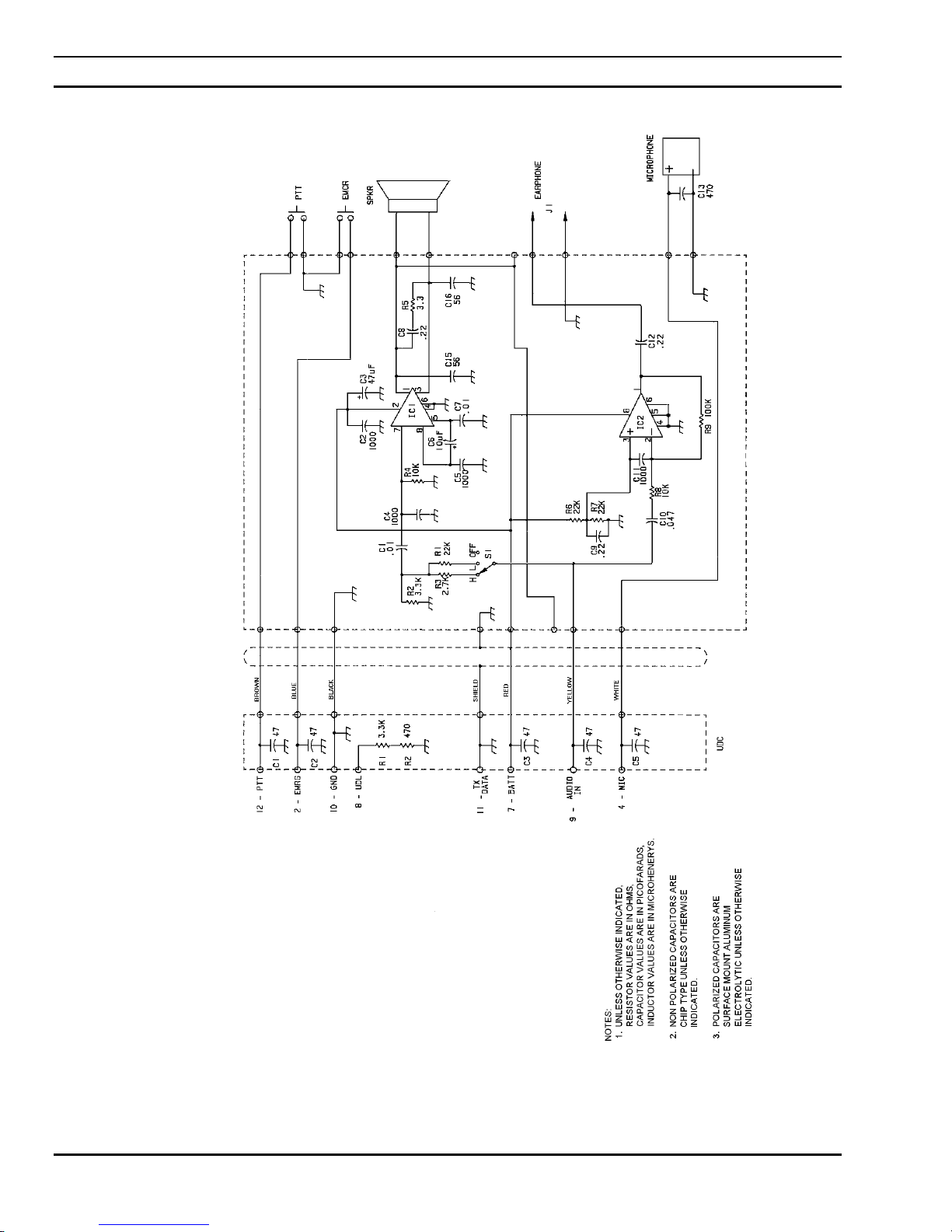
LBI-39060 SCHEMATIC DIAGRAM
M-RK SPEAKER/MIC
344A4189P1 & P3
(818002, Rev. D)
4
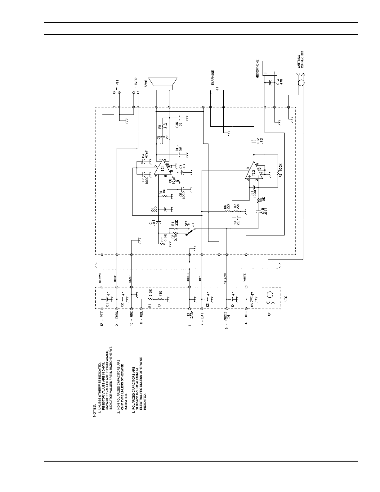
SCHEMATIC DIAGRAM LBI-39060
M-RK SPEAKER/MIC/ANTENNA
344A4189P2 & P4
(818003, Rev. D)
5
 Loading...