

Ericsson 344A3072P8, 344A3072P9 Maintenance Manual
LBI-38708A
Maintenance Manual
Universal
Multi-Unit Charger
Rapid-344A3072P8
Standard-344A3072P9
CA UTION
THESE SERVICING INSTRUCTIONS ARE FOR USE BY QUALIFIED
PERSONNEL ONLY. TO AVOID ELECTRIC SHOCK DO NOT PERFORM ANY SERVICING OTHER THAN THAT CONTAINED IN THE
OPERA TING INSTRUCTIONS UNLESS YOU ARE QU ALIFIED TO DO
SO. REFER ALL SER VICING TO QU ALIFIED SER VICE PERSONNEL.
WARNING:
NOT EXPOSE THIS PRODUCT TO RAIN OR MOISTURE.
CAUTION:
IZED) PLUG WITH AN EXTENSION CORD, RECEPTACLE OR OTHER OUTLET
UNLESS THE BLADES CAN BE FULLY INSERTED TO PREVENT BLADE EXPOSURE.
TO PREVENT FIRE OR ELECTRIC SHOCK HAZARD. DO
TO PREVENT ELECTRIC SHOCK DO NOT USE THIS (POLAR-
ericssonz

LBI-38708
TABLE O F CONT ENT S
IMPORTANT SAFETY INFORMATION .......................................................................................... 3
SPECIFICATIONS............................................................................................................................... 4
DESCRIPTION..................................................................................................................................... 5
INSTALLA TION .................................................................................................................................. 7
INDICATORS....................................................................................................................................... 7
OPERATION......................................................................................................................................... 8
MAINTENANCE INSTRUCTIONS................................................................................................... 9
TROUBLESHOOTING PROCEDURES .............................................. .............................. ................ 14
INTERCONNECT DIAGRAMS
STANDAR D MULTI-UNIT CHARGER ........................................... .......................................... 17
RAPID MULTI-UNIT CHAR GER .............................................................................................. 20
SCHEMATIC DIAGRAMS
STANDAR D MULTI-UNIT CHARGER ........................................... .......................................... 18
RAPID MULTI-UNIT CHAR GER .............................................................................................. 21
ILLUSTRATED PARTS BREAKDOWN
STANDAR D MULTI-UNIT CHARGER ........................................... .......................................... 24
RAPID MULTI-UNIT CHAR GER .............................................................................................. 25
PARTS LIST........ .. .... .. .... .. .... .. .... .. .... .. .... .. .... .. .... .. .... .. .... .. .... .. .... .. .... .. .... .. .... .. .... .. .... .. .... .. .... .. .... .. .... .. .. 26
NOTICE!
This manual covers Ericsson and General Electric products manufactured and sold by Ericsson Inc.
NOTICE!
Repairs to this equipment should be m ade only by an authorized service technician or facility designated by the supplier.
Any repairs, alterations or substitution of recommended parts made by the user to this equipment not approved by the
manufacturer could void the user’s authority to operate the equipment in addition to the manufacturer’s warranty.
This manual is published by
cies of current information, or improvements to programs and/or equipment, may be made by
will be incorporated into new editions of this manual. No part of this manual may be reproduced or transmitted in any form or by any means, electronic or
mechanical, including photocopying and recording, for any purpose, without the express written permission of
NOTE: The Universal Chargers 344A3072 P1 & P8 have been tested and found to comply with the limits for a Class B digital device, p urs ua nt to part 15 of the FCC rules. The se limits are des ign ed to provide reasonable portection against harmful interfere nc e in a residential installation. This e quipment generates, uses and can radiate radio frequ ency energy and, if not insta lled and used in accorda nc e with
the instructions, may ca us e harmful interference to radio communications. However, there is no guarantee that interference w ill not occur in a particular insta llation. If this equipment does c au se ha rmful interference to radio or televis ion reception, which ca n be determined by turning the equipment off and on, the user is encouraged to try to correct the interference by one or more of the following measures:
•
Reorient or relocate the receiving antenna.
•
Increase the separation between the equipment and receiver.
•
Connect the equipment into an outlet on a circuit different from that to which the receiver is connected.
•
Consult the dealer or an experienced radio/TV technician for help.
Copyright© September 1992, Ericsson GE Mobile Communications Inc.
2
Ericsson Inc.,
without any warranty. Improvements and changes to this manual necessitated by typographical errors, inaccura-
Ericsson Inc.,
at any time and without notice. Such changes
Ericsson Inc.

LBI-38708
IMPORTANT SAFETY
INFORMATION
SAVE THIS MANUAL
1.
and operating instructions for Universal Multi-unit
Charger.
2. Before using the battery charger, read all instructions and
cautionary markings on (1) the battery charger, (2) the
battery, and (3) the product using the battery.
CAUTION
3.
Ericsson battery packs using the proper battery sleeve.
Charging any other battery pack or batteries may cause
the battery to burst and cause person al injury or damage.
4. Do not expose charger to rain or snow.
5. Do not use auxiliary equipment not recommended or sold
by the manufactu rer. To d o so ma y r esu lt i n a ri sk of fir e,
electric shock, or injury to persons.
6 To reduce risk of damage to electric plug and cord, pull
by the plug rather than the cord when disconnecting the
charger.
7. Make sure the cord is located so that it will not be stepped
on, tripped over, or otherwise subjected to damage or
stress.
8. An extension cord should not be used unless absolutely
necessary. Use of an improp er extension cor d could result
in a risk of fire and electric shock. If an extension cord
must be used, make sure:
a. That pins on the plug of the extension cord are the
b. That the extensio n cord is properly wir ed and in good
c. That the wire size is large enough for the AC ampere
- To reduce the risk of injury, charge only
same number, size, and shape as those on the
charger’s plug;
condition; and
rating of the charger as specified in Table 1.
- It contains important safety
9. Do not operate charger with damaged cord or plug replace them immediately.
10. Do not operate charger if it has received a sharp blow,
been dropped, or other wise dam aged in a ny way; ret urn it
to a qualified service shop.
11. Do not disassemble the charger; return it to a qualified
service shop when service or repair is required. Incorrect
reassembly may result in a risk of electrical shock or fir e.
12. To reduce risk of electric shock, unplug the ch arger from
the outlet before attempting any maintenance or c leaning.
13. GROUNDING AND AC POWER CORD CONNECTION - To reduce the risk of electrical shock use only a
properly grounded outlet. The charger is e quipped with an
electric cord having an equipment-grounding conductor
and a grounding plug. Be sure that the outlet is properly
installed and grounded in accordance with all local codes
and ordinance s .
DANGER
14.
fit in the outlet, have a proper outlet installed by a qualified
electrician. Improper connection can result in risk of an
electric shock.
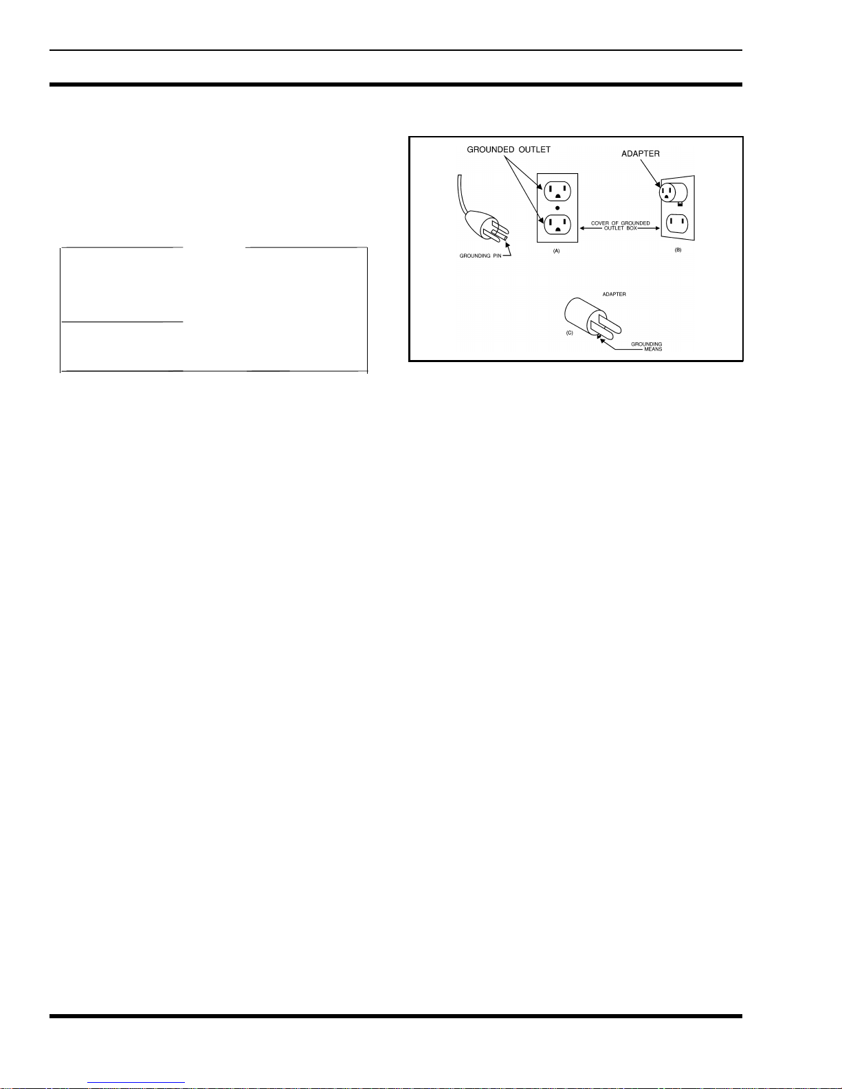
15. The Rapid Charger 120 Vac line cord has a grounding
plug that looks like the plug illustrated in Figure 1. A
temporary adapter, which looks like the adapter illustrated
in sketches B and C, may be used to connect this plug to
a two-pole receptacle as shown in sketch B if a properly
grounded outlet is not available. The temporary adapter
should be used only until a properly grounded outlet can
be installed by a qualified electrician.
DANGER
16.
certain that the center screw of the outlet plate is grounded.
The green-color rigid ear or lug extending from the adapter must be connected to a properly grounded outlet--make
certain it is grounded. If necessary, replace the outlet
cover plate screw with a longer screw that will secure
adapter ear or lug to outlet plate and make ground connection to grounded outlet.
- Never alter the AC cord or plug. If it will not
- Before using an adapter as illustrated, be
LENGTH OF EXTENSION CORD (Ft.)
AWG SIZE OF EXTENSION CORD
TABLE 1
RECOMMENDED MINIMUM SIZE FOR
EXTENSION CORDS
25 50 100 150
18 18 18 16
3
LBI-38708
IMPORTANT SAFETY INFORMATION
17. Care should be taken when placing the charger in service
to insure proper top and bottom ventilation. A minimum
of 1/4" is required between the bottom of the charger and
the surface on which it sits.
NOTE
Due to the temperature characteristics of nickelcadmium batteries, the batteries will not accept a
full charge at temperature extremes. For maximum
capacity, recharge the battery pack at a room tem-
perature of 65° to 85°F, whenever possible.
SPECIFICATIONS
Figure 1 - Grounding Methods
VOLTAGE SOURCE
120 volt switch position 96-144 Vac, 50/60 Hz
230 volt switch position 176-264 Vac, 50/60 Hz
POWER CONSUMPTION
Rapid Charger 170 watts
Standard Charger 30 watts
FUSE RATING
Rapid Charger F1 - 5 Amp 250 volt, fast blow
Standard Charger F1 - 315 mAmp 250 volt, fast blow
F2 - 600 mAmp 250 volt, slow blow
RECHARGE TIME
Rapid Charger 1 hour
Standard Charger 14 hours
OPERATING TEMPERAT URE RANGE +5° to +45°C
(+41° to +113°F)
DIMENSIONS(HxWxD)
Height 4.6 inches (117 mm)
Width 12.4 inches (315 mm)
Depth 18.2 inches (461 mm)
WEIGHT
Rapid Charger 15.7 lb. (7.1 kg)
Standard Charger 15.1 lb. (6.8 kg)
4
LBI-38708
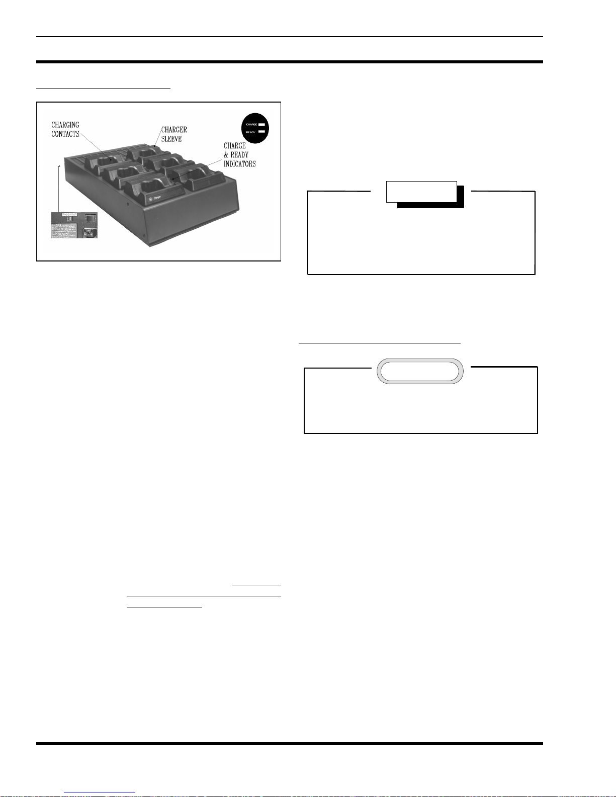
DESCRIPTION
The Universal Multi-unit Charger is designed to charge
Ericsson personal ra dio ba tter y pac ks. Th e c harger is capa ble of charging up to six battery packs at one time and is
available as a Standard or Rapid Charger.
The use of interchangeable battery sleeves permits
charging different battery pack families at the same time (i.e.
two M-RK and four M-PD sleeve inserts in the same
charger). The sleeves allow charging a battery pack alone or
attached to a radio and can be easily installed or removed
from the charger.
Each sleeve has spring loaded electrical charging contacts and contains circuitry unique to charging a pa rticular
family of battery packs. The sleeve is designed to plug easily
into the charger base using guides in the base for self alignment.
Battery Pack sleeves are available for most Ericsson
personal radios including M-PA, M-PD, PCS etc. The following listing identifies the sleeve required for each radio.
RADIO TYPE SLEEVE NUMBER
M-PA, M-PD, 344A3072P5
MTL, PLS, & TPX
PCS 344A3072P6
M-RK 344A3072P7
STANDARD CHARGER
A constant current is developed through the use of
various series resistance combinations. In connection with
the sleeve circuitry, the proper selection of series resistors
controls the current needed for the particular battery pack
being charged. This also includes series resistors selected by
the long or short battery pack microswitch. A portion of the
current flows through the
battery pack is connected and is being charged.
CHARGE
LED indicating the
RAPID CHARGER
The Rapid Multi-unit Charger may also be powered by
either a 120 Vac or 230 Vac 50/6 0 Hz power sour ce. En sur e
the charger’s voltage selection switch is set to the proper
voltage before applying power. Switching on the Charger’s
ON/OFF power switch applies input power to the built-in
power supply board.
The power supp ly board (PS-8) rectif ies the input power
to produce a stable DC voltage for the constant current
regulator PC Bs (CC-8). The po wer supply’ s output is 13 Vdc
at 10 amps which is supplied to the three constant current
regulators.
Each constant current regulator provides a constant current of 1.9 or 1.3 amps for two battery packs via the charge
control PCB (CHG-1). This constant current is selected by a
control signal from the charge control board.
The Rapid Charger is microprocessor controlled and
uses switching current regulators to regulate the charge current. Battery voltage and temperature are monitored by the
microprocessor which controls the
LEDs and the charge enable transistor.
CHARGE
and
READY
The Standard Multi-unit Charger may be powered by
either a 120 Vac or 230 Vac 50/6 0 Hz power sour ce. En sur e
the charger’s voltage selection switch is set to the proper
voltage before applying power. Switching on the Charger’s
ON/OFF power switch applies input power to the built-in
power supply board.
The power supp ly board (PS-9) rectif ies the input power
and produces a stable DC voltage to the A1 printed circuit
board (PCB). Th e po wer su pply’s output is 15 Vdc and up to
1.14 amps which is supplied to the six A1 charger PCBs.
CAUTION
Recharging any battery pa ck or batteries ot her than
the ones your equipment was designed to charge
may result in damage to equipment, leakage, or
explosion.
5
LBI-38708
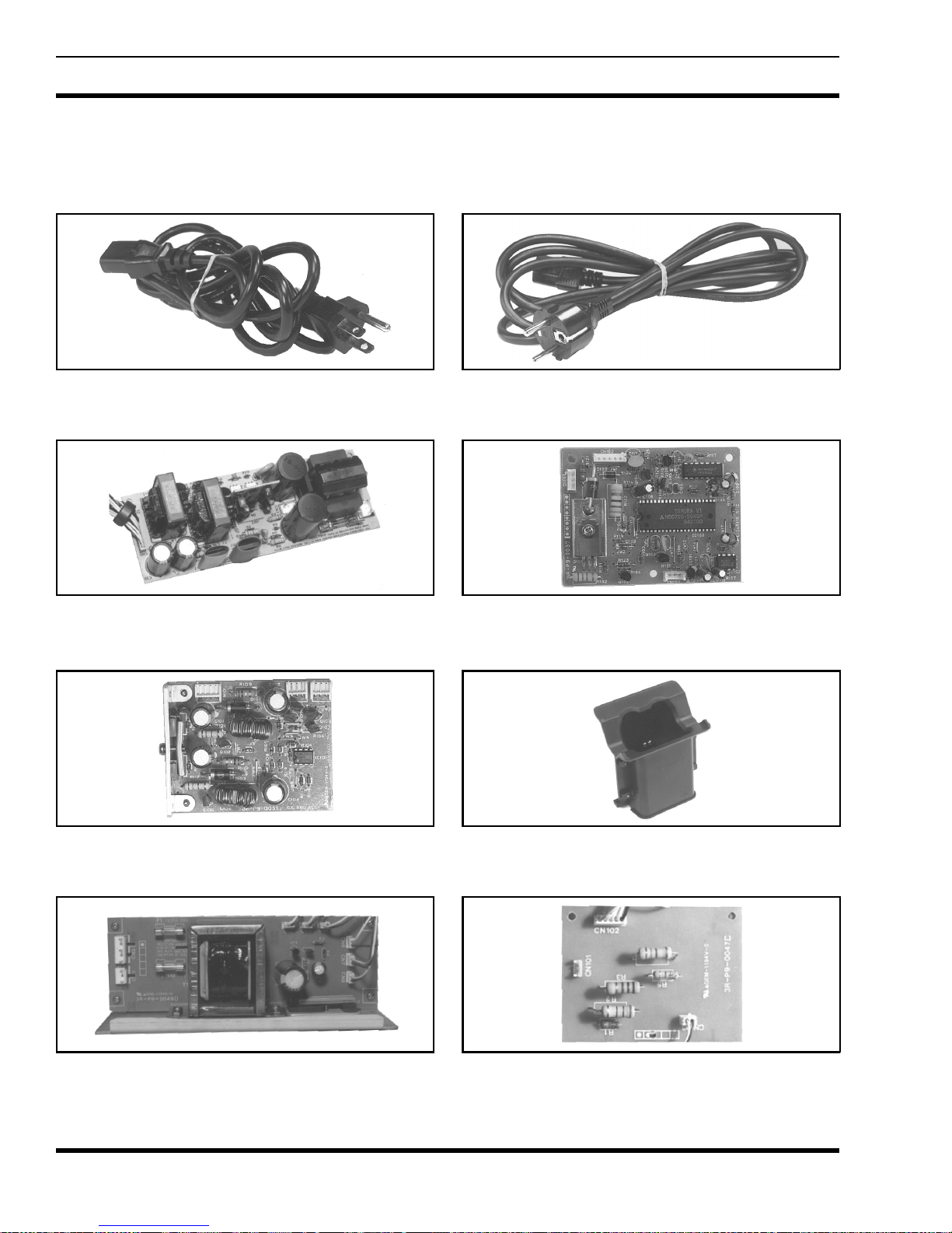
ACCESSORIES AND REPLACEMENT PARTS
The following accessories are available for the Universal Multi-unit Chargers:
120 Vac Line Cord
344A3072P10
Rapid Charger Powe r S up ply
F29/4R-A9-0091
230 Vac Line Cord
344A3072P11
Rapid Charger Control Board
F29/4R-A9-0083
Rapid Chgr Constant Current
F29/4R-A9-0092
STD Charger Power Supply
F29/4R-A9-0095
6
Charger Sleeve
STD Charger Control Board
F29/4R-A9-0096

LBI-38708
INSTALLATION
The Multi-unit Chargers may be located on a flat surface
or mounted on a vertical wall in a convenient location.
Ensure either a 120 V ac or 230 Vac 50/60 Hz source is located
near the charger. Switch charger’s voltage selection switch
to the match the source voltage. Plug the power cord into the
charger and plug the other end into the outlet. When locating
the charger on a flat surfac e be s ure to al low a min imu m of
1/4" clearance around the top and bottom covers to provide
adequate ventilation.
MOUNTING INSTRUCTIONS
When mounting the Universal Multi-unit charger on a
wall be sure the wall is strong enough to support the charger
and a full compliment of radios. Also, ensure either 120 V ac
or 230 Vac 50/60 Hz power is readily available for the
charger.
Hollow walls
be mounted directly to the wall due to the possible weight
(26 lbs max) involved. We suggest you mount the charger on
an 18" x 18" plywood pa nel secured to the wall studs. The
following steps describe the process for installing the panels
and mounting the charger.
-
It is not recommended that the charger
Solid walls
wall, first insert four wood dowels or four fiber, plastic, or
masonry mounting anchors. Use th e following procedure:
1. Using the mounting template provided, locate and
2. Screw the four N o. 8 x 1 1/2" sc rews and m ounting
3. Install charger on mounting spacers by pressing
- T o install the char ger on a brick or c oncrete
mark the charger keyhole mounting points. Drill
holes to match the anchor’s diameter and depth using
a carbide drill bit. Insert the mounting anchors into
the holes.
spacers (provided) into the anchors.
down on the charger allowing the mounting spacers
to seat into the charger keyhole slots. The weight of
the charger will hold it firmly to the wall.
INDICATORS
Standard Multi-unit Charger
1. Locate the studs, studs are n ormally 16" apart, me asured center-to-center.
2. Position the top of the panel at the desired height and
drill a 1/8" pilot hole through the panel into the studs.
Secure the plywood panel to the studs u sing four 2
1/2" long (min) screws.
3. Using the template, locate keyhole slots for the Multiunit charger mounting screws. Install the four No. 8
x 1 1/2" mounting screws and mounting spacers
(provided) . Install charger on mounting spacers by
pressing down on the charger allowing the mounting
spacers to seat into the charger keyh ole slots. The
weight of the charger will hold it firmly to the wall.
STANDARD Multi-unit Charger
(Shown with sleeve installed)
CHARGE (RED) CONTINUOUS
charging at the selected charging rate.
: Indicates battery is
7
LBI-38708
Rapid Multi-unit Charger
RAPID Multi-unit Charger
(Shown with sleeve installed)
STAND-BY Both indicators are OFF. Battery not
installed.
CHARGE (RED) CONTINUOUS: Indicates battery is
charging at the selected charging rate.
READY (GREEN) CONTINUOUS: Indicates charging
is complete and charger has switched
to trickle charge.
PROBLEM
(RED/GREEN)
If both RED and GREEN indicators are blinking
fast, immediately unplu g the charger and return it
for service. If left in this condition, the battery may
be severely overcharged causing personal injury or
damage.
BLINKING FAST: When both indicators are blinking fast, either the output has a short circuit or an abnormal
output condition exists.
WARNING
OPERATION
To Use The Multi-unit Charger
BLINKS SLOWLY: Indicates a
BATTERY FAULT condition which is
preventing an acceptable r apid charg e.
This condition may result if the battery is too hot or cold, weak or dead,
or defecti ve. If the bli nking CHARGE
indicator does not turn to a continuous
RED after 15 minutes, remove and
reinsert the battery.
W eak or Dead Battery - The CHARGE
indicator goes to continuous RED after the battery has an acceptable precharge (typically less than 10
minutes).
Cold or Hot Battery - The CHARGE
indicator stays in a blinking RED condition until the battery temperature
reaches acceptable limits
tery is removed and reinserted to clear
the fault condition.
Defective Ba tter y - Th e CHARGE indicator stays in a blinking RED condition after clearing the fault by
removing and reinserting the battery.
and the bat-
CAUTION
To reduce risk of injury, charge only nickel-cadmium batteries. Othe r types of batteries may burst
causing personal injury or damage.
1. Plug in the charger and turn the charger’s ON/OFF switch
on.
2. Turn the radio OFF and place the radio into the proper
charging sleeve with the speaker facing the front of the
charger. If only charging a battery pack, insert the battery
pack into the charger as indicated on the battery pack.
Make sure the ON-OFF switch on the battery pack is in
the OFF position (M-RK battery packs do not have an
ON/OFF switch).
3. STANDARD MULTI-UNIT CHARGER: The
CHARGE (red) indicator will light indicating the battery
is being charged. To charge the battery to maximum
capacity, let the battery pack charge for at least 14 hours.
4. RAPID MULTI-UNIT CHARGER: The CHARGE (red)
indicator will light indicating the battery is being charged.
(If the RED indicator is blinking slowly - the charger is in
the pre-charging mode. This mode results if the battery
temperature is either too
8
 Loading...