

Page 1
Operator’s Manual
UNIVERSAL MULTI-UNIT
CHARGER
STANDARD & RAPID
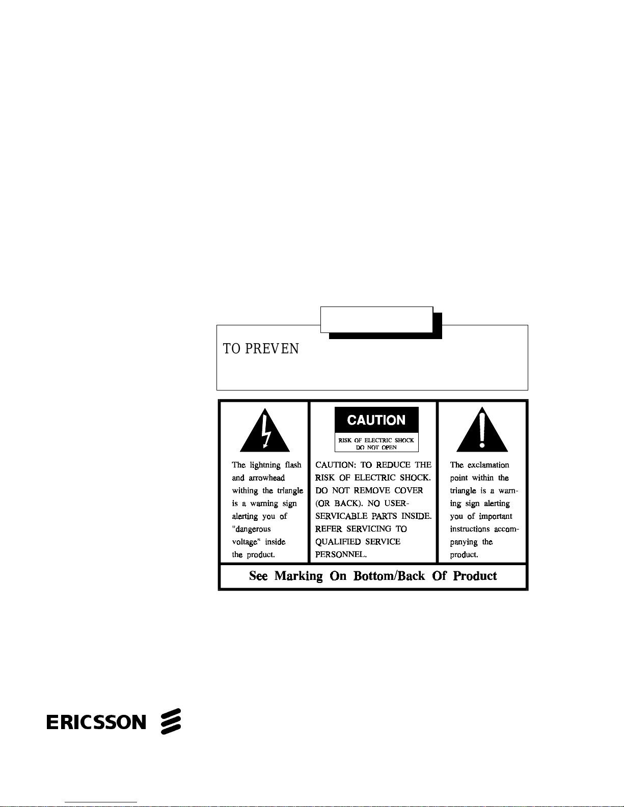
WARNING
TO PREVENT FIRE OR ELECTRIC SHOCK HAZARD DO NOT EXPOSE THIS PRODUCT TO
RAIN OR MOISTURE
ericssonz
Page 2

TABLE OF CONTENTS
Page
IMPORTANT SAFETY INFORMATION . . . . . . . . . . . 3
SPECIFICATIONS . . . . . . . . . . . . . . . . . . . . . . 7
DESCRIPTION . . . . . . . . . . . . . . . . . . . . . . . . 8
INSTALLATION . . . . . . . . . . . . . . . . . . . . . . . 9
INDICATORS . . . . . . . . . . . . . . . . . . . . . . . . . 10
OPERATION . . . . . . . . . . . . . . . . . . . . . . . . . 13
DEFINITIONS . . . . . . . . . . . . . . . . . . . . . . . . . 14
TROUBLESHOOTING CHART . . . . . . . . . . . . . . . 15
ACCESSORIES AND REPLACEMENT PARTS . . . . . . 17
WARRANTY . . . . . . . . . . . . . . . . . . . . . . . . . . 19
NOTE: The Universal Chargers BML 161 51/022 & /024 have been tested and found to comply with the limits for a Class B digital device, pursuant to part 15 of the FCC rules. These limits are designed to provide reasonable portection against harmful interference in a residential
installation. This equipment generates, uses and can radiate radio frequency energy and, if not
installed and used in accordance with the instructions, may cause harmful interference to radio
communications. However, there is no guarantee that interference will not occur in a particular
installation. If this equipment does cause harmful interference to radio or television reception,
which can be determined by turning the equipment off and on, the user is encouraged to try to
correct the interference by one or more of the following measures:
•
Reorient or relocate the receiving antenna.
•
Increase the separation between the equipment and receiver.
•
Connect the equipment into an outlet on a circuit different from that to which the
receiver is connected.
•
Consult the dealer or an experienced radio/TV technician for help.
NOTICE!
This manual covers Ericsson and General Electric products manufactured
and sold by Erics son Inc.
This manual is published by
by typographical errors, inaccuracies of current information, or improvements to programs and/or equipment, may be made
by
Ericsson Inc .
part of this manual may be reproduced or transmitted in any form or by any means, electronic or mechanical, including photocopying and recording, for any purpose, without the express written permission of
Copyright© May 1995, Ericsson Inc.
, at any time a nd w ithout no tice. Such c hanges will be incorportated into new editions of this manual. No
Ericsson Inc.
, without any warranty. Improvements a nd changes to this manual necessitated
Eric sson Inc.
2
Page 3

IMPORTANT SAFETY
INFORMATION
1. SAVE THIS MANUAL - It contains important safety and operating in-
structions for Universal Multi-Unit Charger.
2. Before using the battery charger, read all instructions and cautionary
markings on (1) the battery charger, (2) the battery, and (3) the product
using the battery.
3. CAUTION - To reduce the risk of injury, charge only Ericsson battery
packs using the prope r battery sleeve . Charging any other battery pack
or ba tteries may cause the battery to burst and cause personal injury or
damage.
4. Do not expose charger to rain or snow.
5. Do not use auxiliary equipment not recommended or sold by the manufacturer. To do so may result in a risk of fire, electric shock, or i n j ur y t o
persons.
6 To reduce risk of damage to electric plug and cord, pull by the plug
rather than the cord when disconnecting the charger .
7. Make sure the cord is located so that it will not be stepped on, tripped
over , or otherwise subj ect ed to dam a ge or stres s.
8. An extension cord should not be used unless absolutely necessary. Use
of an improper extension cord could result in a risk of fire and electric
shock. If an exten s ion cord must be used, make sure:
a. That pins on the plug of the extension cord are the same number,
size, and shape as those on the charger’s plug;
b. That the extension cord is properly wired and in good condition;
and
3
Page 4

IMPORTANT SAFETY
INFORMATION
c. That the wire size is large enough for the AC ampere rating of the
charger as specified in Table 1.
TABLE 1
RECOMMENDED MINIMUM SIZE FOR
EXTENSION CORDS
LENGTH OF EXTENSION CORD (ft.) 25 50 100 150
AWG SIZE OF EXTENSION CORD 18 18 18 16
9. Do not operate charger with damaged cord or plug - replace them immediately.
10. Do not operate charger if it has received a sharp blow, been dropped, or
otherwise damaged in any way; return it to a qualified service shop.
11. Do not disassemble the charger; return it to a qualified service shop
when service or re pair is re quired. Incorre ct reassembly may result in a
risk of electrical shock or fire.
12. To re duce risk of electric shock, unplug the charger from the outlet before attempting any maintenance or cleaning.
4
Page 5

IMPORTANT SAFETY
INFORMATION
13. GROUNDING AND AC POWER CORD CONNECTION - To reduce
the risk of electrical shock use only a properly grounded outlet. The
charger is equipped with an e lectric c ord having an equipment-grounding conductor and a grounding plug. Be sure the outlet is properly installed and grounded in accordan ce with all local codes and ord inan ces.
14. DANGER - Never alter the AC cord or plug. If it will not fit in th e outlet, have a proper outlet installed by a qualified electrician. Improper
connection can result in risk of an electric shock .
15. The Rapid Charger 120 Vac line cord has a grounding plug that looks
like the plug illustrated in Figure 1. A temporary adapter, which looks
like t he ada p te r illustrated in s ketches B and C, may be us ed to con nect
this plug to a two-pole receptacle as shown in sketch B if a properly
grounded outlet is not available. The temporary adapter should be used
only until a properly grounded outlet can be installed by a qualified
electrician.
16. DANGER - Be fore using an adapter as illustrated, be certain the center
screw of the outlet plate is grounded. The green- color rigid ear or lug
extending from the adapter must be connected to a properly grounded
outlet--make certain it is grounded. If necessary, replace the outlet
cover plate screw with a longer screw that will secure adapter ear or lug
to outlet plate and make ground connection to grounded outlet.
17. Care should be taken when placing the charger in service to insure
proper t op and bottom ven tilation. A minimum of 1/4" is required between the bottom of the charger and the surface on which it sits.
5
Page 6
IMPORTANT SAFETY
INFORMATION
Figure 1 - Grounding Methods
NOTE
Due to the temperature characteristics of nickel-cadmium batteries,
the batterie s wi ll not acc ept a full c harge at temperature extremes. For
maximum capacity, recharge the battery pack at a r oo m tem per atur e o f
65° to 85° Fahrenheit, whenever possible.
6
Page 7

VOLTAGE SOURCE
120 volt switch position 96-144 Vac, 50/60 Hz
230 volt switch position 176-264 Vac, 50/60 Hz
POWER CON S U MP TION
Rapid Charger 170 watts
Standard Charger 30 watts
FUSE RATING
Rapid Charger F1 - 5 Amp 250 volt
Standard Charger F1 - 315 mA, 250 volt
RECHARGE TIME
Rapid Charger 1 hour
SPECIFICATIONS
F2 - 600 mA, 250 volt
Standard Ch arger 14 hours
OPERATING
TEMPERATURE RANGE + 5° to +45°C
( + 41° to + 113°F)
DIMENSIONS (H x W x D)
Height 4.6 inches (117 mm)
W i dt h 12.4 inches (315 mm)
Depth 18.2 inches (4 61 mm)
WEIGHT
Rapid Charger 15.8 lb. (7.1 kg)
Standard Ch arger 15.2 lb. (6.8 kg)
7
Page 8

DESCRIPTION
The Universal Multi-unit Charger is designed to charge Ericsson personal radio battery packs. The charger is available either as a Standard or
Rapid Charger and is capable of charging up to six battery packs at one
time.
The Standard Multi-unit Charger is capable of fully charging battery
packs in 14 hours and Rapid Desk Charger charges most battery packs in
one hour or less. The use of interchangeable battery sleeves permits charging different battery pack families at the same time (i.e. two M-RK and four
M-PD sleeve inserts in the same charger).
Both the Standard and Rapid Multi-unit Chargers may be powered by
either a 120 Vac (50/60 Hz) or 230 Vac (50/60 Hz) power source. Power
source selection is made by switching the Voltage Selection switch to the
proper source voltage and using the correct power cable (see Accessories
and Replacement parts).
Battery Pack sleeves are available for the following Ericsson personal
radios:
RADIO TYPE SLEEVE NUMBER
M-PA, M-PD, MTL, PLS, & TPX BML 161 51/001
PCS BML 161 51/00 2
M-RK BML 161 51/00 3
MONOGRAM BML 161 51/004
CAUTION
Recharging any battery pack or batteries other than the ones your
equipment was designed to charge may result in damage to equipm ent,
leakage, or explosion.
8
Page 9

PRISM HP BML 161 51/005
INSTALLATION
The Multi-unit Charger may be located on a desk or other flat surface or
mounted on a vertical wall in a convenient location. Ensure either a 120 or
230 Vac 50/60 Hz power source is located near the charger. Check the
charger ’s voltage selection switch and v erify it matches the source voltage.
When locating it on a flat surface be sure to allow 1/4" clearance around the
top and bottom covers to provide adequate ventilation.
When mounting the Universal Multi-charger on a wall be sure the wall
is strong enough to support the charger and a full compliment of radios.
Hollow walls -
It is not recommended that the charger be mounted directly to the wall due to the possible weight (26 lbs max) involved. We suggest mounting the charger on an 18" x 18" plywood panel secured to the
wall st uds. The fo llowing steps describe the proces s for installing the panel
and mounting the charger.
1. Locate the studs, s tuds are normally 16" apart, measured center-to-cen-
ter.
2. Posit ion the top of the panel at the desired height and drill pilot holes
through the panel into the s tuds. Secure the panel to the studs using four
2 1/2" long screws.
3. Using the templat e, locate keyhole slots for the Multi-charger mounting
screws . Install the four No. 8 x 1 1/2" mounting screws and mounting
spacers (provided). Install charger on mounting spacers by pressing
down on the charger allowing the mounting spacers to seat into the
charger keyhole slots. The weight of the charge r w ill hold it firmly to
the wall.
9
Page 10

Solid walls - To install the charger on a brick or concrete wall, first in-
sert four wood dowels or fiber, plastic or masonry mounting anchors. Use
the following procedur e:
1. Using the mounting template provided, locate and mark the charger
keyhole mounting p oints. Drill the holes to match the anchor’s diameter
and depth using a carbide drill. Insert the anchor into the holes.
2. Screw the four No. 8 x 1 1/2" screws and mounting spacers (provided)
into the anchors.
3. Install the charger on the mounting spacers by pressing down on the
charger allowing the mounting spacers to seat into the charger keyhole
slots. The weight of the charger will hold it firmly to the wall.
10
Page 11

INDICATORS
STANDARD MULTI-UNIT CHARGER
CHARGE (RED) CONTINUOUS: Indicates battery is charging at the se-
lected charging rate
11
Page 12

12
RAPID MULTI-UNIT CHARGER
WARNING
If both CHARGE and READY indicators are blinking fast, immediately unplug the charger and return it for service. If left in this
condition, the battery may be severely overcharged causing personal injury or damage.
Page 13

STAND-BY Both indicators are OF F . Battery not installed.
CHARGE (RED) CONTINUOUS: Indicates battery is charging at the se-
lected charging rate.
BLINKS SLOWLY: Indicates a BATTERY FAULT
condition which is preventing an acceptable rapid
charge. This condition may result if the battery is too
hot or cold, weak or dead, or defective. If the blinking
CHARG E indicator does not turn to a continuous RED
after 15 minutes, remove and reinsert the battery.
Weak or Dead Battery - The CHARGE indicator goes
to continuous RED after the battery has an acceptable
pre-charge (typically less than 10 minutes).
READY
(GREEN)
PROBLEM
(RED/GREEN)
Cold or Hot Battery - The CHARGE indicator stays in a
blinking RED condition until the battery temperature
reaches acceptable limits
and the battery is removed
and reinserted to clear the fault condition.
Defective Battery - The CHARGE indicator stays in a
blinking RED condition after clearing the fault by removing and reinserting the battery .
CONTINUOUS: Indicates charging is complete and
charger has switched to trickle charge.
BLINKING FAST: When both indicators are blinking
fast, either the output has a short circuit or an abnormal
output condition exists.
13
Page 14

OPERATION
Using The Desk Charger
CAUTION
For indoor use only. To re duce risk of injury, charge only nickel cadmium type rechargable batteries. Other types of batteries may explode
causing personal injury or damage. Replace defective cords immediately.
1. Plug in the charger and turn it on using the ON/OFF power switch lo-
cated in the rear.
2. Turn the radio OFF and place it into the proper charging sleeve with
the speaker facing the front of the charger. If only charging a battery
pack, properly insert the battery pack into the charger as indicated on
the battery pack making sure the ON-OFF switch on the battery pack is
in the OFF position (M-RK, Monogram or Prism HP battery packs do
not have an ON/OFF switch).
3. STANDARD MULTI-UNIT CHARGER: The CHARGE (red) indica-
tor will light indicating the battery is being c harged The proper charge
current for long or short case battery packs is selected by the insert micro switch . To ch arge the battery to maximum capacity, let the battery
pack charge for at least 14 hours
4. RAPID MULTI-UNIT CHARGER: The CHARGE (red) indicator will
light indicating the battery is being charged. (If the CH ARGE indicator
is blinking slowly - the charger is in the pre-charging mode. The
charger should switch to normal charge within 10 minutes). When the
READY (green) indicator lights - charging is complete and the charger
is in trickle charge mode.
14
Page 15

NOTE
On occasion when charging a new battery or a battery which has been
out of use for a few months, the charger will prematurely switch to the
trickle charge before the battery has been fully charged. If this happens, allow the battery to continue trickle charging overnight. Then
remove and reinsert the battery and observe that the battery goes
through a normal rapid charge before putting it into service.
To Remove A Battery Pack
Simply reach into the cutouts provided in the sides of the ch arging insert
and lift the battery pack out.
DEFINITIONS
Dead Battery Battery pack with low voltage due to long term self
discharge or extreme discharge.
Hot Battery Battery Pack excessively warmed by char ging or en-
vironmental temperature conditions.
Cold Battery Battery pack excessively cooled by an environmental
condition.
Defective Battery Battery pack with one or more of th e internal cells
shorted.
15
Page 16

TROUBLESHOOTING CHART
SYMPTOM
1. RED LED indicator
does not light.
2. Pre-charge too long
RED LED blinks slowly
for over 10 minutes.
(Rapid charg er on ly)
CHECK FOR
1. Power cable not pl ug ged in
securely.
2. Power switch not turn ed on.
3. Battery pack not properly
installed in charger.
4. Defective charger. Return to a
qualified service shop for repair.
5. Charging contacts on the
battery or charg er are dirty.
Clean with soft eraser.
1. Defective battery with shorted
cells.
3. Red charge LED ON for
several seconds then
starts to blink slowly.
(Rapid Charger only)
4. RED and GREN LED’s
blink rapidly (Rapid
Charger only).
16
1.
2.
Hot battery (above 45° C).
Cold battery (below 0° C).
Remove battery and r e-insert
after temperature has stabilized.
1. Defective charger, return
charger to a qualified service
shop.
Page 17

ACCESSORIES AND REPLACEMENT PARTS
Accessories and replacement parts may be obtained from your local
dealer or by calling the Ericsson Inc. After Market Services 24-Hour Toll
Free Number 1-800-368-3277 (USA only) or FAX 1-800- 833-7592. Please
provide the description and part number when ordering [e.g. PCS sleeve,
BML 161 51/002] .
The following pages illustrate and identify the accessories and replacement p arts available. NOTE: Complete c hargers must be ordered using applicable package number.
120 Vac Line Cord
BML 161 51/043
230 Vac Line Cord
BML 161 51/044
NOTE
Only an authorized or certified electronic technician should attempt to
disassemble or service the charger.
Refer to U nive rsal M ult i-unit Charger M ainte nanc e Manu al if it is necessary to change the charger sleeve or to replace printed wiring boards,
components or assemblies.
17
Page 18

Standard Charger Contro l Board
Charger Sleeve
F29/4R-A9-0096
STD Charger Power Supply
F29/4R-A9-0095
See Pg. 8 for sleeve numbers
Rapid Charger Power Supply
F29/4R-A9-0091
Rapid Charger Control Board
F29/4R-A9-0083
18
Rapid Charger Constant Current
F29/4R-A9-0092
Page 19

WARRANTY
A Eric sso n Inc. (herein after "Selle r") warr ants to the or iginal pur chaser fo r use (herei nafter " Buyer") tha t
Equipment manufactured by Seller shal l be free from defects in material, workmanship and title, and
shall conform to its published specifications. With respect to any Eq uip me nt n ot m an ufactured by Seller
)except for integral parts of Seller ’s Equipment to which the warranties set forth above shall apply).
Seller gives no warranty, and only the warranty, if any, given by the manufac- turer shall a pply. Batte ries
are excluded from this war ranty but are warran te d under a separate Nickel- Cadmium Batt er y W ar ra nt y.
B Seller’s obligations set forth in Paragraph C below shall apply only to failures to meet the above warran-
ties ( exc ept a s to tit le) o cc urrin g w ithi n the fol lowi ng pe rio ds of ti me fro m da te of sale to the Buy er and
are conditioned on Buye r’s giving writte n no tice to Selle r with in th irt y (30) da ys of such occurre nce .
1. for fuses, incandescent lamps, vacuum tubes and non-rechargeable batteries, operable on arrival
only
2. for parts and accessories (except as noted in B.1) sold by Seller’s Service Parts Operation, ninety
(90) days.
3. for all other Equipment of Seller’s manufacture, one (1) year.
C If any Equipment fails to meet the foregoing warranties, Seller shall correct the failure at its option (i) by
repairing any defective or damaged part or parts thereof, or (ii) by making available at Seller ’s factory
any necessary repaired or replacement parts. Any repaired or replacement part furn ished hereunder
shall be warranted for the remainder of the warranty period of the Equipment in which it is installed.
Where such failure cannot be corrected by Seller’s reasonable efforts, the partie s will nego tiate an equitable adjustment in price. Labor to perform warranty service will be provided at no charge only for the
Equipment covered under Paragraph B.3, and only during the first three (3) months following the date of
sale to the Buyer. Thereafter, labor will be charged at prevailing rates. T o be eligible for no-ch arge labor ,
service must be performed by an Authorized Service Center or other Servicer approved for these purposes either at its place of business during norma l business hours, for mobile or personal equipment, or
at the Buyer’s location, for fixed location equipment. Service on fixed location equipment more than
thirty (30) miles fr om the Service Center or other approved Servicer ’s plac e of business will Include a
charge for transportation. Equipment located off-shore is not eligib le fo r no -ch ar ge labo r.
D. Seller’s obligation under Paragraph C shall not apply to any Equipment, or part thereof, which (i) has
been modified or otherwise altered other than pursuant to Seller’s written instr uction s or written approval
or, (ii) is normally consumed in operation or, (iii) has a normal l ife inherently shorter than the warranty
periods specified i n Paragraph B , or (iv) i s not properl y stored, installed, used, maintained or repaired.
or, (v) has been subjected to any other kind of misuse or detrimental exposure, or has been involved in
an accident.
E The preceding paragraphs set forth the ex clusive remedies for claims (ex cept as to title) based upon
defects in or nonconf ormity of the Eq uipment , whethe r the cl aim is in cont ract, wa rranty, tort (incl uding
negligence), strict liability or otherwise, and however instituted. Upon the expiration of the warranty period, all such liability shall terminate. The foregoing warranties are exclusive and in lieu of all other warranties, whether oral, written, expressed, implied or statutory. NO IMPLIED OR STATUTORY
WARRANTIES OP ME RC HA NTABILITY OR FITNESS FO R PARTICULAR PURPO SE SHALL APPLY.
IN NO EVENT SHALL THE SELLE R BE LIABLE FOR ANY INCIDENTAL, CONSEQUENTIAL, SPECIAL, INDIRECT OR EXEMPLARY DAMAGES.
This warranty applies only within the United States.
1-800-528-7711 (Outside USA, 804-528-7711)
Page 20

Ericsson Inc.
Private Radio Systems
Mountain V iew Road
Lynchburg,Virginia 24502
1-800-5 28-7711 (Outside USA, 804-528-7711)
AE/LZT 123 1871 R1A
Printed in U.S.A.
 Loading...