

Page 1

INSTRUCTIONS
FOR
MULTIPLE RECEIVER POWER SUPPLY 19E501707G4 & G5
TABLE OF CONTENTS
Page
DESCRIPTION ...........................................................................................................................................Front Page
MAINTENANCE........................................................................................................................................Front Page
CIRCUIT ANALYSIS .................................................................................................................................Front Pag e
OUTLINE DIAGRAMS
Multiple Receiver Power Supply ......................................................................................................................2
Amplifier Board A801 ............ ...... ...... ...... ...... .... ...... ...... ...... ...... .... ...... ...... ...... ...... ...... .... ...... ...... ...... ...... .... .....3
Battery Standby/Charger (19C320677).............................................................................................................4
SCHEMATIC DIAGRAMS (Includes Parts List and Production Changes)
Multiple Receiver Power Supply (19E501707G4, Rev. A)........................... ...................................................5
Multiple Receiver Power Supply (19E501707G5, Rev. A)........................... ...................................................7
Audio Amplifier (A804)..... .... .... .... ... ... .... .... .... .... ... ... .... .... .... .... ... ... .... .... .... ... ... .... .... .... .... ... ... .... .... .... .... ... ... ...9
Battery Standby Kits (19C320677G4 & G5).................................................................................................. 10
Battery Standby/Charger Kits (19E501707G3 & G6)....................................................................................11
Multiple Receiver Power Supply (19E501707G4)......................................................................................... 14
Multiple Receiver Power Supply (19E501797G5)......................................................................................... 16
TEST PROCEDURES.................................. ............................................................................................................ .. 1
INSTALLATION INSTRUCTIONS
Battery Standby/Charger Kits (19C320677G3-G6) ....................................................................................... 12
Power Supply Modification Kit (19A137630) ...............................................................................................13
DESCRIPTION
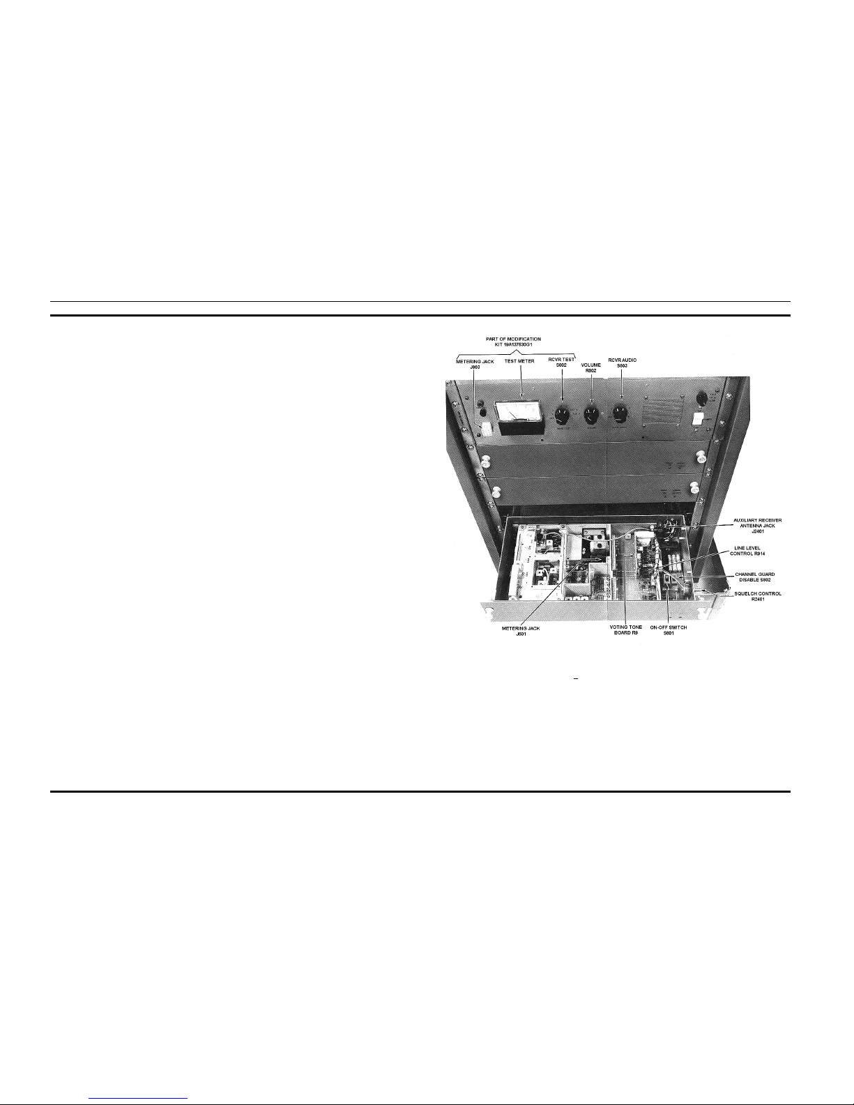
The MASTR® II Multiple Receiver Power Supply is
designed for supplying a maximum of eight MASTR II
auxiliary receivers. The supply will operate at 60 Hertz
(Model 19E501707G4) or 50 Hertz (Model 19E501707G5).
An audio power amplifier is included in the supply along with
a speaker mounted on the front panel. A switch is provided
for connecting each receiver line audio output to the amplifier
and speaker. The receiver audio PA is not used in multiple
auxiliary receiver applications.
Modification Kit 19A137630G1 (Option 9707) provides
a metering circuit and meter mounted to the front panel of the
supply. This kit allows functional checks of up to eight
receivers. The metering points are the same as in the MASTR
II station receivers.
MAINTENANCE
To insure high operating efficiency and to prevent mechanical and electrical failures from interrupting system operations, routine checks should be made of all mechanical and
electrical parts at regular intervals. To check the Auxiliary
Receiver functions, refer to the Test Procedure (see Table of
Contents).
CIRCUIT ANAL YSIS
Multiple Receiver Station Power SupplyWhen the power
supply ON-OFF switch S801 is in the ON position, 121 VAC
is connected across the primary of T801 (T802 in the 50 Hz
model). The power transformer is a ferro-resonant type which
has inherent good line regulation. C801 serves as a resonating
capacitor across the secondary taps of the transformer.
ERICSSONZM
Ericcson GE Mobile Commu nications Inc.
Mountain View Road•Lynchburg Virginia 24502
ERICSSONZM
Printed in U.S.A.
LBI-30731E
Copyright © 1977, Gene ral Electric Company
Page 2
The transformer steps the input voltage down to 12 volts and
this lower voltage is applied to the bridge rectifier composed of
CR1-CR4 mounted on heat sink A802. The rectified output of
the bridge is fed to the filter composed of C1 and C2 (mounted
on A802) and L801.The output of the filter is connected through
P802 to the printed board A801 which, in turn, connects the A+
to the receiver power jacks J3-J10. Fuse F1 serves to protect the
A+ circuit.
Multiple Receiver Audio Circuits
The audio from the Auxiliary Receiver line driver is connected through J2402-20 (LINE DRIVER MON) on the Auxiliary Receiver to pin 3 of each power plug (P2) on the station
harness. The audio is then coupled through the receiver jacks
(J3-J10) on the Power Supply to switch S803. The position of
S803 (RCVR AUDIO) determines which receiver audio is
selected.
The selected audio is then passed to VOLUME control R802
and the properly adjusted audio is then connected to the input
(pin 7) of the monolithic audio amplifier IC, AR1. This amplifier delivers 1.25 Watts to the station speaker LS801. The
discrete resistors and capacitors connected to AR1 insure the
proper roll-off characteristic of 300 to 3000 Hertz. The audio
power amplifier in the MASTR II Auxiliary Receiver is disabled
in this application.
Battery Standby (Option 9700)
The Battery Option provides a means for automatic transferring the receiver power supply to a customer furnished
standby battery when the primary AC power fails.
The supply is automatically transferred back to primary AC
power when power is restored. The MASTR II Receiver Battery
Standby Kit 19C320677G5 (Option 9700) consists of Battery
Standby printed board 19C320677G4 and a pair of connectors
(P1 & P2) for connecting the board into the power supply
circuit. Refer to the Installation Instructions (see Table of Contents).
When the station power supply is operating properly, approximately +15 V olts appears at P1-2. This voltage is rectified
at CR3 and CR4 to energize relay K1. When the power supply
is off, K1 is de-energized and the relay switches in the battery
as the power source.
121 VAC Battery Standby/Charger
(Option 9701)
The MASTR II Receiver Battery Standby/Charger Kit for
121 VAC operation (19C320677G3) consists of Battery
Standby/Charger printed board 19C320677G2, connectors P1
and P2 and 121 V AC transformer T1. The same transfer function
as in Option 9700 is performed, along with a battery charging
function that keeps the battery charged as long as the station is
on primary AC power (121 VAC, 60 Hz). The charging current
decreases as the standby battery reaches full charge. The maximum charge rate is 2 amperes DC.
Transformer T1 supplies +15 Volts to P1-2. This voltage is
rectified by CR1 and CR2 and applied to the current regulator
Q1 (pass transistor) and Q2 (driver transistor). R2 is a current
sensing resistor which limits the battery charging current to a
maximum of 2 amperes. A voltage divider, consisting of R3, R4
and R5, allows a variable voltage (adjusted by R4) to set the
base bias of Q2. This in turn controls the conduction of Q1. C1
provides filtering for the input voltage. The regulator output is
fused by F1, providing overload protections.
242 VAC Battery Standby/Charger
(Option 9702)
The MASTR II Receiver Battery Standby/Charger Kit for
242 VAC operation (19C320677G6) consists of Battery
Standby/Charger printed board 19C320677G2, connectors P1
and P2 and 242 VAC transformer T2. The transfer circuit and
charger circuit operate in the same manner as described for
Options 9700 and 9701.
1. SLIDE OUT RECEIVER TO BE TESTED.
2. APPLY A 1000 MICROVOLT ON-FREQUENCY S IGNAL MODULATED BY 1,000 HERTZ WITH
±3 kHz DE-
VIATION TO THE AUXILIARY RECEIVER ANTENNA
JACK J2402
3. SELECT THE RECEIVER AUDIO WITH SWITCH
S803 ON THE POWER SUPPLY. DISABLE CHANNEL
GUARD WITH S802 (ON THE RECEIVER SYSTEM
BOARD) IF PRESENT.
4. ADJUST VOLUME CONTROL (R802 ON POWER
SUPPLY) FOR DESIRED AUDIO LEVEL.
5. CONNECT METERING CABLE 19C321099G1 BETWEEN J803 (PART OF 19A137630G1 KIT ON POWER
SUPPLY) AND J601 (ON RECEIVER CHASSIS).
6. SWITCH S802 (PART OF 19A137630G1 ON POWER
SUPPLY) THROUGH THE METERING POSITIONS AND
OBSERVE TYPICAL READINGS ON METER.
7. WITH SWITCH S802 IN SUP V POSITION, METER
SHOULD READ SUPPLY VOLTAGE OUTPUT ±.05
VOLTS.
8. IF STANDBY BATTERY IS USED, CHECK FOR 12
VOLT BATTERY CONDITION BY PLACING RCVR
TEST SWITCH S802 IN BAT V POSITION.
9. FOLLOW STEPS 1 THROUGH 8 FOR ALL OTHER
RECEIVERS IN STATION.
TEST PROCEDURES
LBI-30731
1
Page 3
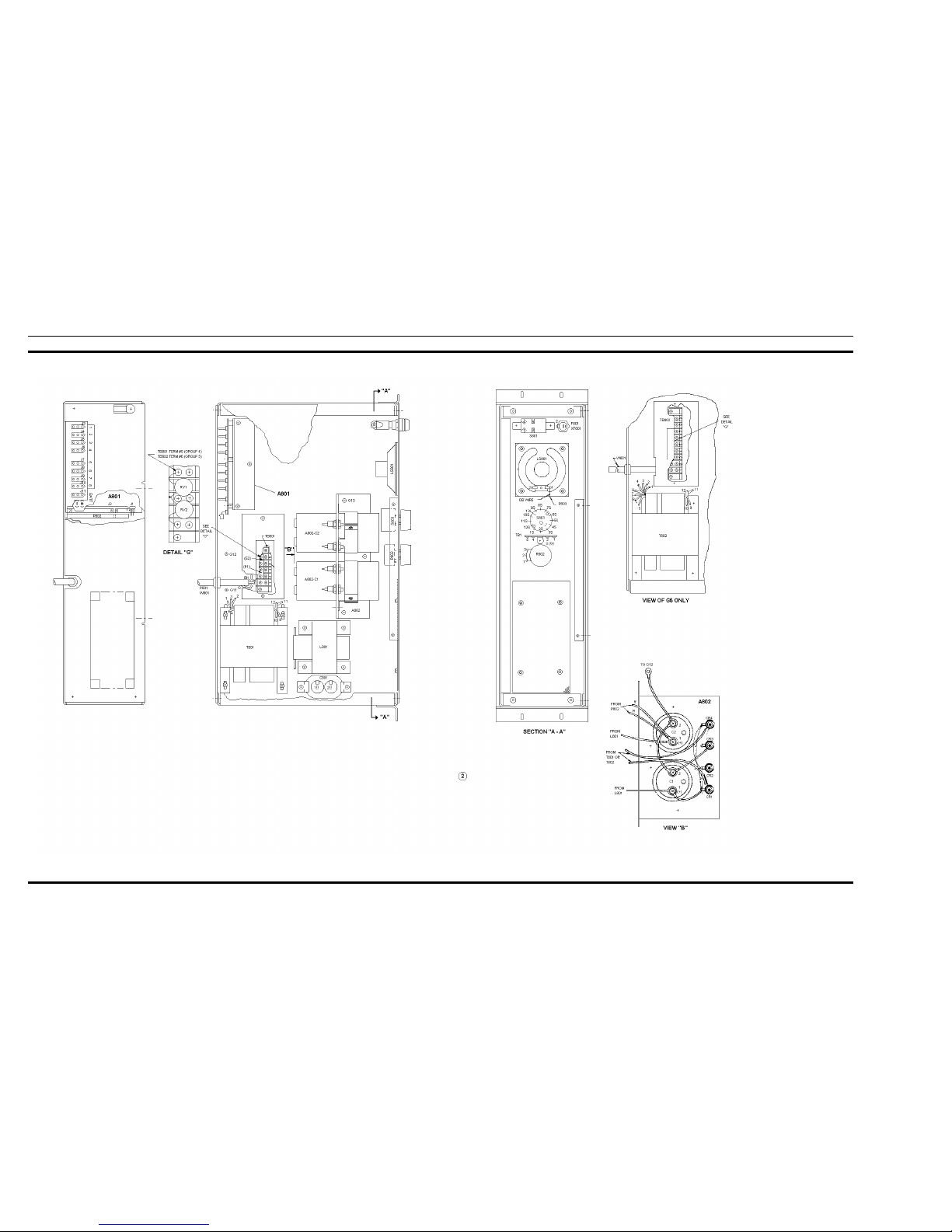
OUTLINE DIAGRAM
MULTIPLE RECEIVER POWER SUPPLY
19E501707G4 & G5
(19E501726, Sh. 2, Rev. 3)
LBI-30731
2
Page 4
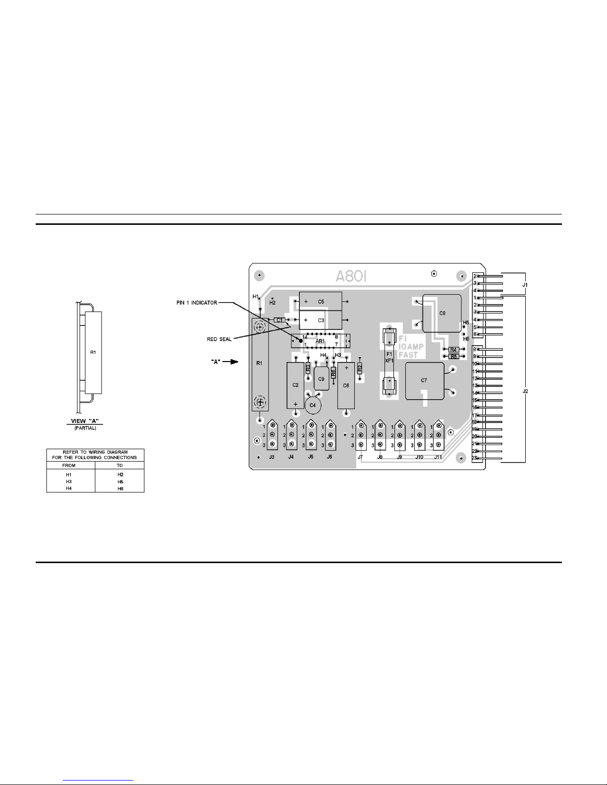
OUTLINE DIAGRAM
AMPLIFIER BOARD A801
(19D423418, Rev. 0)
(19D417724, Sh. 2, Rev. 1)
LBI-30731
3
Page 5
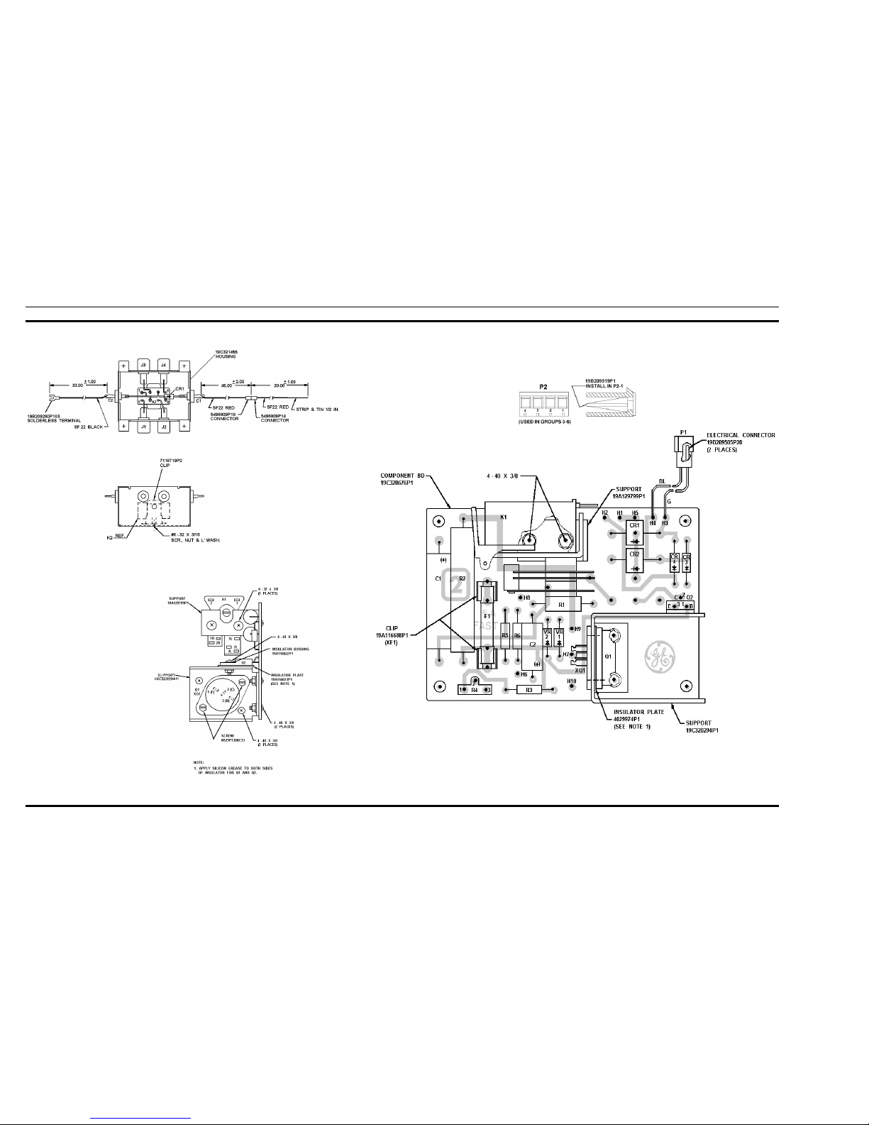
OUTLINE DIAGRAM
BATTERY STANDBY/CHARGER
19C320677
(19C321445, Rev. 2)
(19C320676, Sh. 2, Rev. 2)
(19C321634, Rev. 0)
LBI-30731
4
Page 6
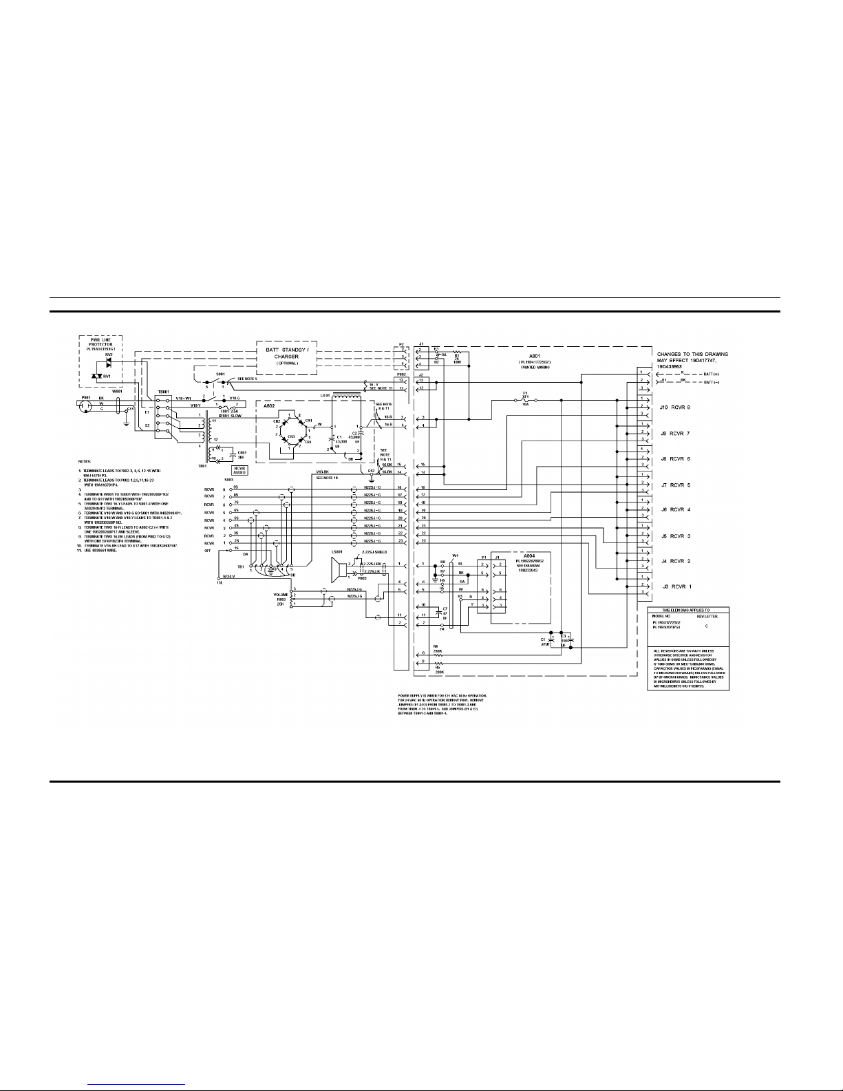
SCHEMATIC DIAGRAM
MULTIPLE RECEIVER POWER SUPPLY
19E501707G4, Rev. A
(19D433655 Sh. 1, Rev. 2)
LBI-30731
5
Page 7

PARTS LIST
LBI-30731
6
Page 8

MULTIPLE RECEIVER POWER SUPPLY
19E501707G5, Rev. A
(19D433656, Rev. 2)
SCHEMATIC DIAGRAM
LBI-30731
7
Page 9

PARTS LIST
LBI-30731
8
Page 10

AUDIO AMPLIFIER A804
SCHEMATIC DIAGRAM PARTS LIST
(19B233943, Sh. 1, Rev. 2)
LBI-30731
9
Page 11

PARTS LISTSCHEMATIC DIAGRAM
BATTERY STANDBY KIT
19C320667G4 & G5
(19C321114, Rev. 3)
LBI-30731
10
Page 12

SCHEMATIC DIAGRAM
BATTERY STANDBY/CHARGER KITS
19C320677G3 & G6
(19D417739, Rev. 7)
LBI-30731
11
Page 13

INSTALLATION INSTRUCTIONS
BATTERY STANDBY/CHARGER KITS
19C320677
PARTS LIST
(19E501708, Rev. 2)
LBI-30731
12
Page 14

INSTALLATION INSTRUCTIONS
PARTS LIST
MODIFICATION KIT 19A137630G1
(19B232690, Rev. 1)
LBI-30731
13
Page 15

SCHEMATIC DIAGRAM
MULTIPLE RECEIVER POWER SUPPLY
19E501707G4
(19D429560, Rev. 2)
LBI-30731
14
Page 16

PARTS LIST
LBI-30731
15
Page 17

SCHEMATIC DIAGRAM
MULTIPLE RECEIVER POWER SUPPLY
19E501707G5
(19D429561, Rev. 3)
LBI-30731
16
Page 18

PARTS LIST
LBI-30731
17
 Loading...