

Ericsson 19D902797G5 Maintenance Manual
Printed in U.S.A.
LBI-39127A
MAINTENANCE MANUAL
851-870 MHz, 110 WATT POWER AMPLIFIER
19D902797G5
TABLE OF CONTENTS
Page
DESCRIPTION . . . . . . . . . . . . . . . . . . . . . . . . . . . . . . . . . . . . . . . . . . F ront Page
SPECIFICATIONS . . . . . . . . . . . . . . . . . . . . . . . . . . . . . . . . . . . . . . . . . . . . . 1
CIRCUIT ANALYSIS . . . . . . . . . . . . . . . . . . . . . . . . . . . . . . . . . . . . . . . . . . . 1
POWER AMPLIFIER . . . . . . . . . . . . . . . . . . . . . . . . . . . . . . . . . . . . . . . . . 1
Small Signal Gain Stage . . . . . . . . . . . . . . . . . . . . . . . . . . . . . . . . . . . . . 1
Driver Module . . . . . . . . . . . . . . . . . . . . . . . . . . . . . . . . . . . . . . . . . . 1
Final Power Stag e . . . . . . . . . . . . . . . . . . . . . . . . . . . . . . . . . . . . . . . . 1
Power Sense and I solation Stages . . . . . . . . . . . . . . . . . . . . . . . . . . . . . . . . 1
POWER CONTROL . . . . . . . . . . . . . . . . . . . . . . . . . . . . . . . . . . . . . . . . . . . . 1
Theory of Operation . . . . . . . . . . . . . . . . . . . . . . . . . . . . . . . . . . . . . . . . . . 2
Signal Interface . . . . . . . . . . . . . . . . . . . . . . . . . . . . . . . . . . . . . . . . . . . . 2
BLOCK DIAGRAM . . . . . . . . . . . . . . . . . . . . . . . . . . . . . . . . . . . . . . . . . . . . 1
TROUBLESHOOTING GUIDE . . . . . . . . . . . . . . . . . . . . . . . . . . . . . . . . . . . . . . 3
POWER AMPLIFIER READ INGS . . . . . . . . . . . . . . . . . . . . . . . . . . . . . . . . . . . . 3
IC DATA . . . . . . . . . . . . . . . . . . . . . . . . . . . . . . . . . . . . . . . . . . . . . . . . . . 3
ASSEMBLY DIAGRAM . . . . . . . . . . . . . . . . . . . . . . . . . . . . . . . . . . . . . . . . . . 4
PARTS LIST . . . . . . . . . . . . . . . . . . . . . . . . . . . . . . . . . . . . . . . . . . . . . . . . 6
OUTLINE DIAGRAM . . . . . . . . . . . . . . . . . . . . . . . . . . . . . . . . . . . . . . . . . . . 7
ASSEMBLY DIAGRAM . . . . . . . . . . . . . . . . . . . . . . . . . . . . . . . . . . . . . . . . . . 7
SCHEMATIC DIAGRAM . . . . . . . . . . . . . . . . . . . . . . . . . . . . . . . . . . . . . . . . . 8
PARTS LIST . . . . . . . . . . . . . . . . . . . . . . . . . . . . . . . . . . . . . . . . . . . Back Cover
DESCRIPTION
The 800 MHz MASTR III Power Amplifier Assem-
bly is a wide band RF power amplifier operating over the
851-870 MHz range without tuning. Its main function is
to amplify the 10 mW FM signal from the Transmitter
Synthesizer to the rated RF output at the antenna port.
The output of the Power Amplifier Assembly is adjustable from rated power to 10dB below rated power at the
PA output J104.
The assembly consists of a printed wiring board (A1)
and associated components, including a power module
and an RF power transistor, mounted to the heat sink
assembly. The printed wiring board (A1) contains both
the power amplifier circuitry and the power control circuitry. The heatsink assembly includes a copper heat
spreader for the power transistor.
Unfiltered supply voltage, A+, for the power amplifier circuits enters the assembly via feedthrough capacitor, C1. Power cable W4 routes the A+ from C1 to J103
on the PWB. Filtered A+ voltage for the power control
circuit enters the assembly via control cable W13 which
connects to the PWB at J201.
ericssonz
Ericsson Inc.
Private Radio Systems
Mountain View Road
Lynchburg, V i r ginia 24502
1-800-528-7711 (Outside USA, 804-528-7711)
SYMBOL PART NO.
DESCRIPTION
4 SBS 123 01/10 Spring nut.
5 19A702339P510 Screw, thread forming,
flat head.
6 19A701312P5 Washer, plain steel, 3.5
mm.
7 19A702381P510 Screw, thread forming,
pan head.
9 19A700136P19 Sleeve
10 105 8567/1 Guard, fan.
11 19A701863P12 Clamp, loop.
13 19A700033P6 Washer, lock, ext tooth.
14 19A700034P5 Nut, hex, steel.
B1
and
B2
BKV 301 216/02 DC fan.
W1 344A3337P4 Cable.
WT1
and
WT2
7142645P1 Conductor, splice.
PA FAN PLATE ASSEMBLY
188D6127G1
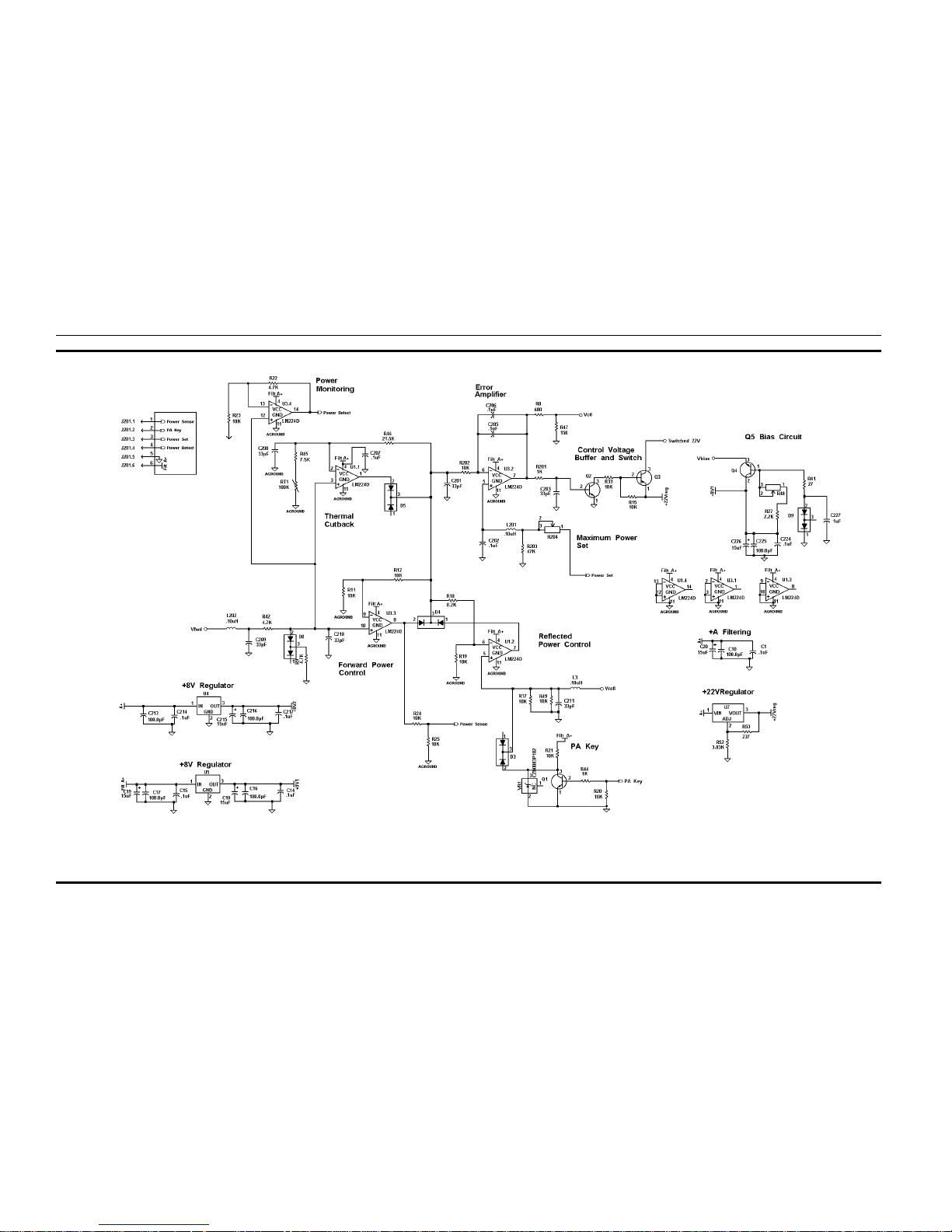
POWER AMPLIFIER BO A RD A1
19D902794G5
(188D5792, Sh.2, Rev. 1)
OUTLINE AND SCHEMATIC DIAGRAMS
LBI-39127A
9
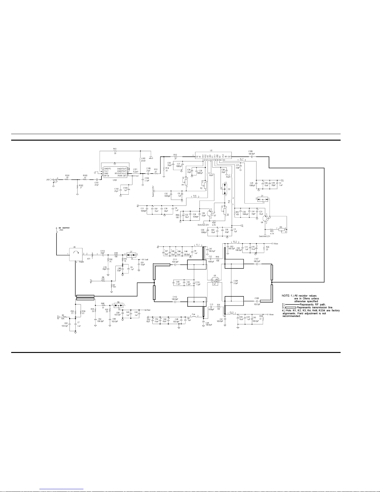
POWER AMPLIFIER ASSEMBL Y
19D902797G5
(188D5792, Sh. 1, Rev. 1)
SCHEMATIC DIAGRAM
LBI-39127A
8
 Loading...