

Ericsson 19B801507P1, 19B801507P4 Maintenance Manual

Maintenance Manual
LB I-31864D
Printed in U.S.A.
Mobile Communications
VEHICULAR
CHARGER UNIT
19B801507P1, P4

Copyright © September 1987, General Electric Company
TABLE OF CONTENTS
Page
SPECIFICATIONS . . . . . . . . . . . . . . . . . . . . . . . . . . . . . . . . . . . . . . . . . . . . . . . . . . . . 1
DESCRIPTION . . . . . . . . . . . . . . . . . . . . . . . . . . . . . . . . . . . . . . . . . . . . . . . . . . . . . . 2
OPERATION . . . . . . . . . . . . . . . . . . . . . . . . . . . . . . . . . . . . . . . . . . . . . . . . . . . . . . . 2
CHARGE ONLY . . . . . . . . . . . . . . . . . . . . . . . . . . . . . . . . . . . . . . . . . . . . . . . . . . 2
CHARGE AND MONITOR . . . . . . . . . . . . . . . . . . . . . . . . . . . . . . . . . . . . . . . . . . . . 2
MOBILE CONFIGURATION . . . . . . . . . . . . . . . . . . . . . . . . . . . . . . . . . . . . . . . . . . . 3
SPECIAL OPERATING PROCEDURES FOR THE TPX 8403/8603 RADIOS . . . . . . . . . . . . . . . . 3
CIRCUIT ANALYSIS . . . . . . . . . . . . . . . . . . . . . . . . . . . . . . . . . . . . . . . . . . . . . . . . . . . 3
CHARGER BOARD . . . . . . . . . . . . . . . . . . . . . . . . . . . . . . . . . . . . . . . . . . . . . . . . 3
DISPLAY FULL BOARD . . . . . . . . . . . . . . . . . . . . . . . . . . . . . . . . . . . . . . . . . . . . . . 5
EXTERNAL ANTENNA . . . . . . . . . . . . . . . . . . . . . . . . . . . . . . . . . . . . . . . . . . . . . . 5
INSTALLATION . . . . . . . . . . . . . . . . . . . . . . . . . . . . . . . . . . . . . . . . . . . . . . . . . . . . . 5
MAINTENANCE . . . . . . . . . . . . . . . . . . . . . . . . . . . . . . . . . . . . . . . . . . . . . . . . . . . . . 5
DISASSEMBLY PROCEDURES . . . . . . . . . . . . . . . . . . . . . . . . . . . . . . . . . . . . . . . . . . 5
ADJUSTMENT PROCEDURES . . . . . . . . . . . . . . . . . . . . . . . . . . . . . . . . . . . . . . . . . . 5
TROUBLESHOOTING PROCEDURES . . . . . . . . . . . . . . . . . . . . . . . . . . . . . . . . . . . . . . 5
TEST ADAPTER . . . . . . . . . . . . . . . . . . . . . . . . . . . . . . . . . . . . . . . . . . . . . . . . . . . . . 6
LIST OF TABLES
TABLE 1 - QUICK CHECKS . . . . . . . . . . . . . . . . . . . . . . . . . . . . . . . . . . . . . . . . . . . . . . . 6
TABLE 2 - EQUIPMENT STATUS . . . . . . . . . . . . . . . . . . . . . . . . . . . . . . . . . . . . . . . . . . . 6
TABLE 3 - V OLTAGE READINGS . . . . . . . . . . . . . . . . . . . . . . . . . . . . . . . . . . . . . . . . . . . 6
SPECIFICATIONS*
INPUT POWER 11.1 TO 16.5 Volts
DC, negative ground
CURRENT DRAIN 2.6 A maximum
INPUT CURRENTS
Standby 1 mA maximum
Radio Squelched, Trickle Charge 300 mA maximum
Rated Audio, Rapid Charge 2600 mA maximum
CHARGE TIME
Standard High Capacity Batteries 3 Hours
Extra High Capacity 4 Hours
CHARGE CAPACITY AND TIME VS TEMPERATURE (Standard, High Capacity)
Temperature
Time Capacity
+5°C (+41° F) 3.3 Hours 100%
+25°C (+77° F) 3.0 Hours 100%
+45°C (+113° F) 2.7 Hours 70%
INDICATORS
Radio Engaged Red
Charge Red
Ready Green
Xmit Red
RATED AUDIO POWER 12 Watts (<% distortion)
SQUELCHED FM HUM and NOISE 65 dB
ALTERNATOR NOISE REJECTION
Receive 60 dB below rated audio
Transmit 60 dB below 4.5 kHz Deviation
MICROPHONE IMPEDANCE 600 Ohms
SPEAKER IMPEDANCE 4 Ohms
DIMENSIONS (H x W x D) 22.6 x 15 x 7 cm (8.9 x 5.9 x 2.7 ins.)
WEIGHT 1.4 kG (3.1 lb)
* These specifications are intended primarily for the use of the service technician.
LB I-31864 LB I-31864
1
DESCRIPTION
The Ericsson GE Vehicular Charger Units convert an MPA, M-PD or TPX Personal Series radio into a mobile configuration when the radio unit is latched into the charger. It
may be used to charge a battery pack only, as a Monitor Receiver and battery charger, or as a two way vehicular radio
and battery charger. The Vehicular Charger connects the radio to an external antenna and provides a full 12 watts audio
output to an external speaker. It will recharge the Standard,
High or Extra High capacity batteries.
The external antenna, microphone, PTT circuit, speaker,
and charging contacts are automatically connected when the
radio is latched into the charger. Radio Detect switch S1, located in the battery compartment, applies power to the
charging circuit when the radio is inserted. A second switch
senses the size of the battery pack and adjusts the charging
rate accordingly.
Heat sensors constantly monitor the temperature of both
the battery pack and the charging insert. When a cold battery
pack is inserted into the charging insert, the charger will wait
until the battery pack has warmed up to within about 10°C
of ambient. The charger will then, automatically, apply the
high charge rate. When the battery pack overcharges enough
to heat the cells 10°C above ambient, the charger will switch
from fast charge to trickle charge.
The charger also has a memory that is set when the
charger switches from the high charging rate to the trickle
charge rate, and is reset when the battery pack is removed
from the charging insert. If a hot battery is in the charging
insert and the memory has not been reset, the charger will
remain at the trickle charge rate. If the memory has been reset the charger will wait until the battery pack has cooled before automatically switching to fast charge. If a fully charged
battery pack is removed from the charging insert and then
reinserted, it will charge for about 1/2 hour until the cell reheats.
A voltage cut off circuit also has been incorporated to
prevent overcharging and “ gassing” of the battery pack.
Battery voltage is constantly monitored and, if the battery
pack charge terminal voltage exceeds 9.5 volts, high rate is
terminated and the LED READY light is turned on.
If the VOLUME switch (attached to the rotary volume
control) is in the OFF position, only the charging function
operates regardless of the latch position.
If the radio is not latched, and the ON/OFF switch on the
radio is on, audio will be heard from the radio speaker.
Note: The radio must have been turned on before being inserted into the charger. The external microphone, speaker,
and outside antenna are not connected until the latch is engaged.
If the VOLUME switch is on, when the radio is latched,
the speaker, microphone and antenna in the personal radio
are disconnected and connections are automatically made to
the charger and its external microphone, speaker, and antenna. In addition, latching the radio causes the power
switch to be turned on, supplying voltage to the audio amplifier and dead battery power supply. It also turns the RADIO
ENGAGED LED on. The personal radio is powered on regardless of the position of its power switch.
If the radio is turned off (switch on battery), latching the
radio into the charger turns on a regulated 8.0 volt power
supply which powers the portable radio while the battery is
being charged. Dead battery operation is provided during
transmit by connecting the 8.0 volt power supply across the
battery during PTT operation.
OPERATION
Temperature characteristics of nickel cadmium batteries,
prevent a full charge at temperature extremes. For a maximum charge, recharge the battery pack at ambient room temperature or between 65 and 85 degrees F.
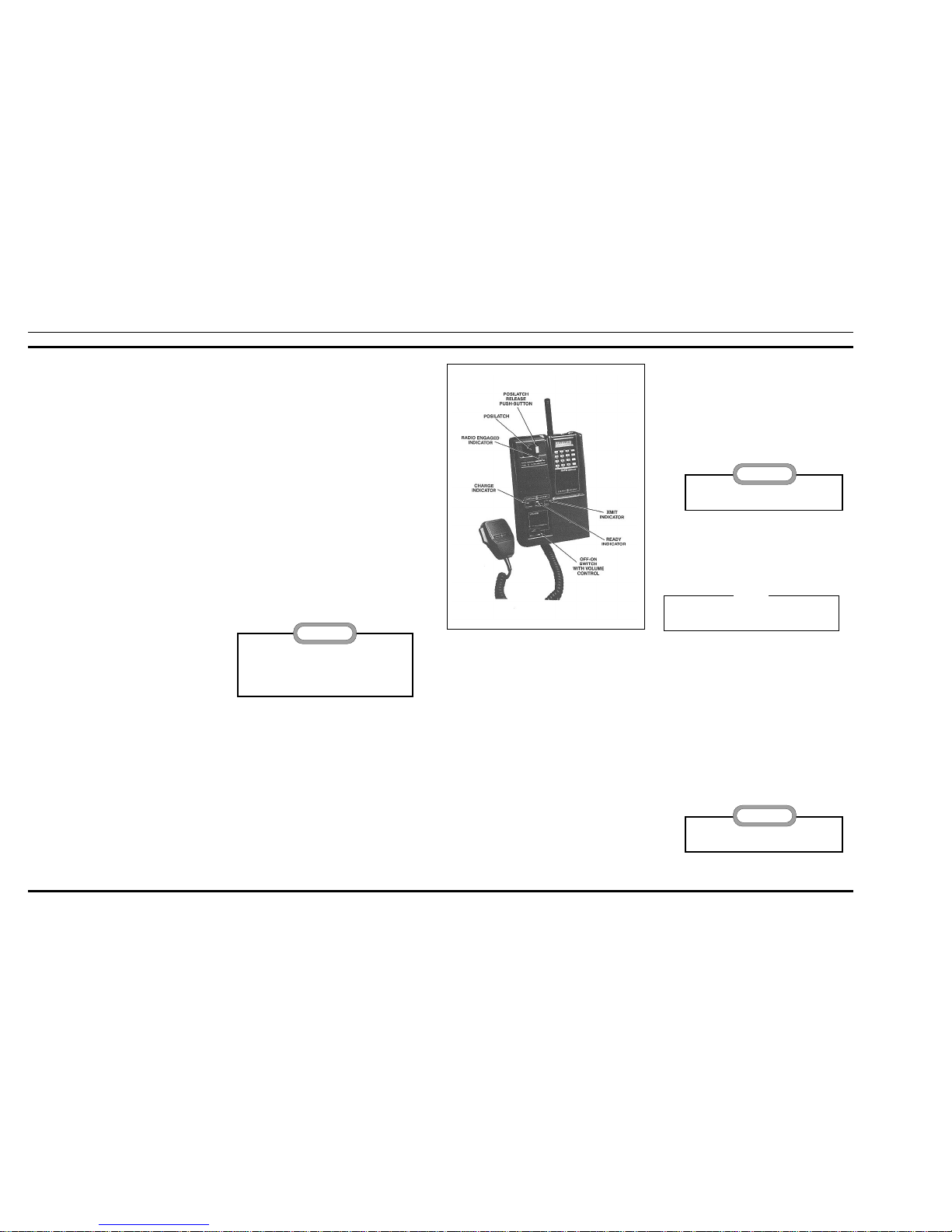
Four indicators provide status information for the
charger/radio combination. A red LED indicator, RADIO
ENGAGED, turns on when the radio is inserted properly
into the charger and a second red indicator labeled CHARGING will light, indicating the battery is being charged. When
the battery pack is fully charged a green LED indicator labeled READY will light and the charger will automatically
switch from a rapid charge rate to a trickle charge rate. A red
XMIT indicator lights when the external PTT switch is
pressed, indicating the transmitter is keyed. (The radio must
be properly engaged). Refer to Figure 1 for location of controls and indicators.
Three operational modes are possible:
• Charge battery pack only
• Monitor receive frequency (s) only and charge battery
pack.
• Full radio operation and charge battery pack.
CHARGE ONLY
The following procedures will permit recharging of the
portable radio unit battery pack only. No activation of the vehicular charger POSILATCH or the VOLUME switch is required.
1. Set po wer switch on portable radio unit battery pack
to OFF position.
2. I nsert portable radio unit into charging compartment
with its speaker facing outward (see Figure 2.).
3. The red CHARGE indicator will light and remain lit
until the portable radio unit is removed or until the
vehicular charger unit circuits sense that the battery
pack has reached total charge capacity, at which time
the green READY indicator will also light, indicating
that the charger has switched to trickle charge rate.
4. Remove the portable radio unit from the charger compartment as shown in Figure 2.
CHARGE AND MONITOR
The following procedures will permit recharging of the
portable radio unit battery pack and also permit the radio to act
as a monitor receiver. No activation of the vehicular charger
POSILATCH or the VOLUME switch is required.
1. Set power switch on the portable radio unit battery
pack to ON position.
2. I nsert portable radio unit into charging compartment
with its speaker facing outward (see Figure 2.).
3. The red CHARGE indicator will light and remain lit
until the portable radio unit is removed or until the
vehicular charger unit circuits sense that the battery
pack has reached its total charge capacity, at which
time the green READY indicator will also light, indicating that the charger has switched to trickle charge
rate.
4. Remove the portable radio unit from the charger compartment as shown in Figure 2.
* Trademark of General Electric Company
The Vehicular Charger is designed to recharge the
Standard, High, and Extra High capacity battery
pack. Attempting to recharge any other battery pack
or batteries may result in damage to equipment,
leakage, or explosion.
CAUTION
Figure 1 - Vehicular Charger
DO NOT use the antenna to remove the portable radio from the charging compartment.
CAUTION
The portable radio is not connected to the external
antenna in this mode.
NOTE
DO NOT use the antenna to remove the portable radio from the charging compartment.
CAUTION
LB I-31864 LB I-31864
2

MOBILE CONFIGURATION
The following procedures permit the recharging of the portable radio unit battery pack and the functional conversion of
the portable radio unit into a mobile configuration.
1. The power switch on the portable radio unit battery
pack may be in either the ON or OFF position.
2. I nsert portable radio unit into charging compartment
with its speaker facing outward (see Figure 2.).
3. S lide the POSILATCH toward the portable radio unit
until you feel it engage and the red RADIO ENGAGED indicator lights.
4. Turn the VOL UME switch on the vehicular charger
unit to the ON position. Then adjust the VOLUME
control for a comfortable listening level from the external speaker.
5. The red CHARGE indicator will light and remain lit
until the portable radio unit is removed or until the
vehicular charger unit circuits sense that the battery
pack has reached its total charge capacity, at which
time the green READY indicator will also light, indi-
cating that the charger has switched to trickle charge
rate.
6. The red XMIT indicator will light each time the PTT
switch on the external microphone is activated.
7. To remove the portable radio unit from the charging
compartment, press the push-button release on the
POSILATCH and slide the latch away from the portable radio unit. The red RADIO ENGAGED indicator
will turn off and the portable radio unit can be removed from the charging compartment (see Figure
2.).
SPECIAL OPERATING PROCEDURES
FOR THE TPX 8403/8603 RADIOS
The Vehicular Charger unit will accept either the M-PA,
M-PD or TPX series Personal Radio Units. However, since
the TPX series operates to the requirements of the GEMARC V system, the following operational procedures must
be observed when a TPX radio is used in conjunction with
the Vehicular Charger Unit.
1. When initiating a call, the push-to- talk switch
(PTT) must be keyed and then released to hear the
channel acquisition tone. The audio from the vehicular charger external speaker is muted each time
the PTT is keyed.
2. When the TPX 8603 (with DTMF option) radio is
used in the vehicular charger, it is recommended
that telephone interconnect or dispatch overdial
calls be made using the number stored in the TPX’s
memory locations. Numbers may be directly dialed
into the unit but they will not be accompanied with
audible feedback tones.
CIRCUIT ANALYSIS
The Vehicular Charger is comprised of a Charger board,
LED board, Display Full board, and a UDC board.
CHARGER BOARD
The Charger board contains the charging circuit with
voltage and temperature cut-off circuits, an 8 volt regulator
circuit, and a 12 watt audio amplifier.
Charging Circuit
When power is first applied to the charger, the voltage at
pin 5 of Comparator A7 is higher than at pin 6 due to the
charging time of C18. The higher voltage causes the output
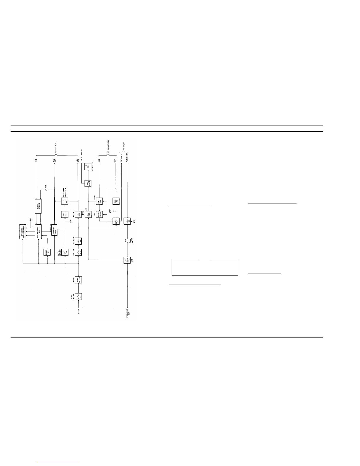
at pin 7 of A7 to go high, keeping A13 turned off. This allows the battery to start charging. A block diagram of the
Vehicular Charger is shown in Figure 4.
Charging current flows through series connected resistors R21 and R22 to regulator transistor Q3. The output of
Q3 is connected to the positive charging contact of the battery. Test Point TP2 provides a convenient place to monitor
the positive battery contact. A portion of the charging current is routed through resistor R24 and transistor Q2 to turn
on CHARGE LED DS3 on the LED board and to provide a
trickle charge when Q2 turns off. The series connected
charge circuit determines the high charge rate and is controlled by the temperature cut off circuit.
Charger Control Circuit
The Charger Control circuit consists of a temperature cut
off circuit and battery charged memory circuit. The temperature cut off circuit consists of integrated circuit A13, a
bridge circuit comprised of R29, R30, R33, thermistors RT1
and RT (BATT), and associated circuitry. Temper ature cut
off IC A13 monitors the temperature of the charging insert
through thermistor RT1 and the temperature of the battery
pack through internal thermistor RT (BATT). It also controls
transistors Q3 and Q4, turns the “READY” indicator on
when the battery pack is fully charged, and provides memory to prevent the same battery pack from being recharged at
the high rate.
Thermistors RT1 and RT (BATT) are connected with
R29, R30, and R33 to form a bridge circuit (see Figure 3).
The output of the bridge circuit is connected to terminals 13
and 14 of A13.
When the battery pack temperature is more than 10°C
(18°F.) below ambient, thermistor RT (BATT) exhibits a
high resistance, causing the voltage on A13-13 to be larger
than the voltage on A13-14. (The same thing would occur if
there were no battery pack present). There is no output from
A13-6 or A13-10. Transistor Q3 and LED READY indicator
DS2 remain off. The battery pack charges at the trickle
charge rate, determined by series resistance R24, until the
temperature is less than 10°C below ambient. At less than
10°C below ambient, the voltage at A13-13 is still larger
than the voltage on A13-14, the output at A13-6 goes high
causing transistor Q4 to conduct, turning Q3 on and beginning the high rate charge.
Figure 2 - Inserting And Removing Portable Radio Unit
DO NOT use the antenna to remove the portable radio from the charging compartment.
CAUTION
Figure 3 - Simplified Temperature Cut Off Circuit
LB I-31864 LB I-31864
3
As the battery pack temperature increases to 10°C above
ambient at end of charge, the voltages at A13-13 and A13-14
become equal, indicating the bridge circuit is balanced and the
battery pack is fully charged. A14-6 goes low, causing Q4 to
stop conducting. Q3 cuts off and the charge rate switches from
the high charge rate to the trickle charge rate . The equal voltages on A13-13 and A13-14 cause the output at A13-10 to go
high, turning READY indicator DS2 on.
A memory circuit internal to A13 is set so that the same
battery can not be recharged at the high rate unless it first has
been discharged or removed from the charger. When the battery pack is removed from the charging insert, RT (BATT) is
removed from the bridge circuit causing the bridge to again be
unbalanced. A13 senses the bridge in an unbalanced state, the
voltage A13-13 being larger than the voltage on A13-14, and
resets the charger memory. Microswitch S1 will also remove
power from the charger circuits, causing the memory to reset.
Voltage Controlled Cut Off
The voltage controlled cut off circuit monitors the battery
voltage and cuts off regulator Q3 when the battery charging
terminal voltage exceeds 9.5 Vdc. It is comprised of Comparator A7, Charge Control IC A13, and associated circuitry.
A reference voltage derived from voltage divider R37, R38,
R41, and zener diode CR12 is applied to pin 2 of Op-Amp A7.
Resistor R43 is adjusted for a battery charging terminal voltage
of 9.5 Vdc. A voltage equal to the reference voltage on pin 2 is
applied to pin 3 of A7. This causes A7-1 to go high, applying a
lesser voltage to A13-14 than is applied to A13-13. This causes
A13 to turn Q3 off and turn READY indicator DS2 on.
Power Input And 8 Volt Regulator
A positive 13.8 Vdc from the vehicle battery is supplied to
the Charger board through a 5 ampere fuse and J1-6. Diode
CR14 provides reverse voltage polarity protection. Voltage
regulator A1 regulates the vehicle input battery voltage (13.8
Vdc) down to +8.0 Vdc and supplies it to the circuitry in the
personal radio while the battery in the personal radio is being
charged.
When a radio is inserted into the charger, radio detect microswitch S1 closes and applies 13.8 Vdc to charging control
circuit A13 through a line filter consisting of C1, C2, C7, and
L1. 13.8 Vdc is also applied through J7-4, VOLUME control
on-off switch S11, J7-5, J9-1, RADIO ENGAGED (latch)
switch S3 to Comparator A5, audio amplifier A12 and to 8 volt
regulator A1.
Input voltage to regulator A1 is applied to pins 11 and 12.
The output of A1 controls the base of NPN pass transistor Q1,
causing it to increase or decrease conduction as required by the
load. Q1 functions as a variable resistor. The regulated output
voltage is set to 8.0 Vdc by variable resistor R5. TP1 provides
a convenient place to monitor the 8.0 Vdc output of regulator
A1. The regulated 8.0 Vdc output is applied directly to the radio, or through contacts 3 and 4 of K2 and to the battery charging terminal. K2 is controlled by the microphone PTT switch
through inverter A3 and is energized when the PTT switch is
operated. K2 allows operation of the radio even though the battery may be dead.
Audio Amplifier A12 (12 Watts)
Audio amplifier A12 is an integrated circuit used to amplify receive audio from the radio to a level of 12 watts. The
amplified audio is then applied to a 15-watt, 4-ohm speaker
through J1-4 &5.
Receive audio (audio out) from the radio is applied to the
input of audio amplifier, A12-10, through the UDC connector
and cable assembly CA1 and J6-6 on the Charger board, contacts 8 & 9 on analog switch A9, and volume control/ on-off
switch VR1/S11. The speaker is connected through P1 to J1.
The audio input level from the radio is controlled by volume
control/on-off switch VR1/S11.
A12 contains internal protection circuitry to safeguard
against line surges, thermal overloads, and speaker shorts to
ground. Input voltage (13.8 Vdc) from the battery is applied to
A12-6.
External Microphone
The external microphone circuit consists of buffer/amplifier A5 and Q5, audio delay circuit Q6, analog switch A9, and
PTT inverter/buffer A3.
Audio Delay
Prior to operating the PTT switch, audio delay transistor
Q6 is turned on and Capacitor C65 charged through CR15 and
R54 (13.8 Vdc). During this time Q6 and closed contacts A9-3
& 5 and 8 & 9 apply ground to the receive audio line from the
radio and the external mic audio line to prevent any unwanted
audio from entering the 12 - watt audio amplifier.
Figure 4 - Vehicular Charger W/12 Watt Amplifier
During charging there is one diode drop between the
(+) charge terminal and the (+) terminal of the battery pack.
NOTE
LB I-31864 LB I-31864
4
 Loading...