

Ericsson 19A705860P1, 19A705860P2, 19A705870P1, 19A705870P2 Maintenance Manual
Printed in U.S.A.
MAINTENANCE MANUAL
CELLULAR HANDSETS
19A705860P1 & P2 (Basic)
19A705870P1 & P2 (Extended Features)
TABLE OF CONTENTS
Page
SPECIFICATIONS . . . . . . . . . . . . . . . . . . . . . . . . . . . . . . . . . . Front Cover
DESCRIPTION . . . . . . . . . . . . . . . . . . . . . . . . . . . . . . . . . . . . 1
TEST SPECIFICATIONS . . . . . . . . . . . . . . . . . . . . . . . . . . . . . . . . 1
ADJUSTMENTS . . . . . . . . . . . . . . . . . . . . . . . . . . . . . . . . . . . 2
OUTLINE DIAGRAM . . . . . . . . . . . . . . . . . . . . . . . . . . . . . . . . . 3
IC DATA . . . . . . . . . . . . . . . . . . . . . . . . . . . . . . . . . . . . . . . 3
SCHEMATIC DIAGRAM . . . . . . . . . . . . . . . . . . . . . . . . . . . . . . . . 4
PARTS LIST . . . . . . . . . . . . . . . . . . . . . . . . . . . . . . . . . . . . . 5
SPECIFICATIONS
POWER SUPPLY
Nominal 12.5 Vdc
Range 10 to 16 Vdc
No failure or lack of function within this range.
CURRENT DRAIN (CU Power)
On Hook, No Audio Less than 25 mA
Rated Audio 100 mA
OPERATING TEMPERATURE RANGE
Nominal 24°C
Operating Range -30°C to +60°C
VCC VOL TA GE
At 25°C 5.0 Vdc to 5.4 Vdc, typical
At 30°C 5.5 Vdc to 5.9 Vdc, typical
At 70°C 5.0 Vdc to 4.6 Vdc, typical
ERICSSONZM
Ericsson GE Mobile Communications Inc.
Mountain View Road • Lynchburg Virginia 24502
LBI-38412A
DESCRIPTION
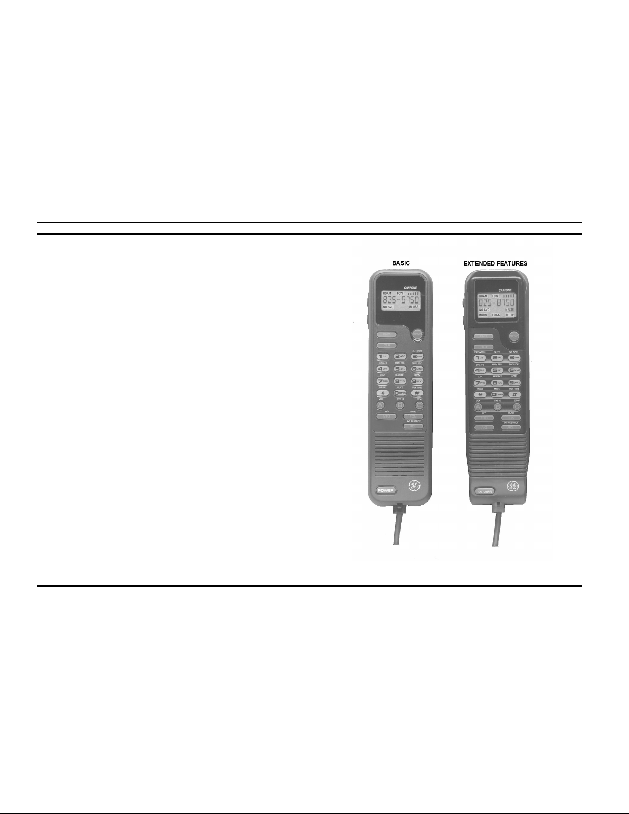
The handsets, shown in Figure 1, consists of a single printed
circuit board containing the following:
•
Numerical and function keypad
•
Liquid Crystal Display
•
All audio and logic circuitry
The printed circuit board conta ins t he micr ophone pream plifier, earpiece amplifier, speaker amplifier, keypad switches, a
microcomputer and LCD driver, receive and transmit data buffers, a 5 volt regulator and backlight LED’s and circuitry.
Although the Basic (19A705860P1) and Extended
(19A705870P1) models of the handset differ in external appearance, they are the same electronically. The Extended model has
one extra key "
A-Z
" and indicators for
"HORN", "LOCK"
and
"MUTE"
.
Audio from the electret microphone (B1) is amplified by
U1-A and passed to the transmit audio path of the radio.
Four bit microcomputer U5 (MB88543) scans the keypad and
controls the LCD. The microcomputer also controls the LED
backlighting of the display and keypad. When a key is pressed
on the keypad, an ASCII code is generated by the microcomputer
and serially transmitted to the mobile. The key release and a
hookswitch change also send ASCII codes to the mobile. At
power-up the handset sends a code to identify itself. The handset
receives commands from the mobile to control the display (indicators, alpha and numeric characters) control the call timer , turn
backlight on or off and interrogates status of han dset or hookswitch.
TEST SPECIFICATIONS
MICROPHONE
1.
Sensitivity
- An input level of 97 dB SPL produces
an output of 150 mV rms ± 5 dB. [
dB SP
L =
20
LOG 10 (P/Po
): P is the rms sound pressure in
Pascals and Po =
2 X 10
-5
Pascal]
2.
Distortion
- For an input signal of less than 1%
distortion, the output distortion does not exceed 3%
from 300 Hz to 3000 Hz.
RECEIVER
1.
Off Hook Sensitivity
- A one (1) kHz, 100 mV rms
input signal produces an output of 94 ± 3 dB SPL,
measured at the artificial ear.
2.
Distortion
- For an input signal of 100 mV rms with
less than 1% distortion, the output distortion is less
than 5% as measured at the artificial ear from 300
Hz to 3000 Hz.
3.
Ear Protection
- An audio limiter is provided to
ensure that the maximum acoustic output does not
exceed 120 dB SPL.
4.
On Hook Sensitivity
- A 1 kHz tone, 100 mV rms
input signal produces an output of 80 ± 6 dB SPL
as measured in the free field.
SIDETONE LEVEL
The acoustic to acoustic sidetone response is such that a 1000
Hz, 97 dB SPL transmit audio input signal produces 85 ± 6 dB
SPL at the artificial ear.
ON/OFF
There is a momentary switch in the handset that is sensed in
the mobile to control the 12 V supply to the handset.
SERIAL DATA
The serial data format is a pseudo RS-232 format. Specifically, it is an asynchronous serial bus operating between Vcc and
0 volts.
Baud Rate
300 ±5%
Bit Pattern
One (1) start two (2) stop, eight (8)
data and no parity .
Format
0 to Vcc inverted with Vcc being a no
data condition.
Vcc
4.5 to 6.0 Vdc
Keypad Data
High-Open Collector drive less than
50 mA current drain.
Display Data
High Open Collector drive less than 50
mA current drain
Low 0.8 V maximum
Copyright © January 1991, Ericsson GE Mobile Communications Inc.
Figure 1 - Basic (19A705860P1) And E xtended (19A705870P1) Handsets
LBI-38412
1
 Loading...