

Page 1
GUIDE TO ASSEMBLY OF ERICA SYNTHS MULTIMODE VCF
If you are reading this, most probably, you are about to build the
Erica Synths DIY Multimode VCF! It’s a multimode filter with a CV
control over cutoff and resonance and simultaneous LP, BP and HP
outputs for serious modular patches. The core of the VCF is highly
stable, custom multimode VCF chip AS3320 (produced in Riga,
btw).
The Multimode VCF kit comes in three versions:
1) Set of 2 PCBs + AS3320 IC + mechanical parts (PCB connectors
and spacer),
2) Set of 2 PCBs + + AS3320 IC + mechanical parts (PCB connectors
and spacer) + panel,
3) Full kit.
FEATURES:
• Simultaneous LP, BP and HP outputs
• CV control over cutoff and resonance
• Cutoff CV attenuverter
• Volume drop compensation, as resonance is increased
• High temperature stability
• Skiff-friendly design
SPECIFICATIONS:
• Audio input amplitude 10Vptp
• CV amplitude (full sweep) -5V - +5V
• Panel width 10HP
• Module depth 35mm
• Power consumption 36mA@+12V, 36mA@-12V
1
3
4
2
5
6
1
2
3
4
5
6
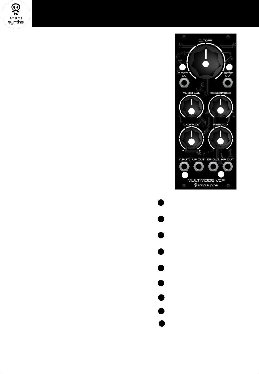
The big knob makes a difference! This is the
filter cutoff frequency control.
Adjust the input signal level with this knob!
This knob adjusts resonance level. The module
has volume drop compensation, so with
increasing resonance, the audio volume will not
reduce
This is the cutoff CV attenuverter
This is the cutoff CV input
7
8
9
This is the resonance CV input
7
This is the resonance CV attenuator
8
Patch the audio signal here!
9
These are the VCF outputs
Page 2
Take precautions with regard to electrostatic discharge (ESD) safety. Handling components should be done
in an electrostatically safe environment. Use personal and workplace grounding. Any discharge (even a
minor one) from your body to a component may permanently damage it.
Our PCBs have silkscreened both component values and designators nevertheless we highly recommend
you to print out the files with the component placement before you start assembly of the module. And,
please, at least take a look at this manual!
Some components are marked as NU (not used) – leave those unpopulated! Some components are market
as OPTION (those are for optional modifications) – leave those unpopulated for now.
ASSEMBLY
1
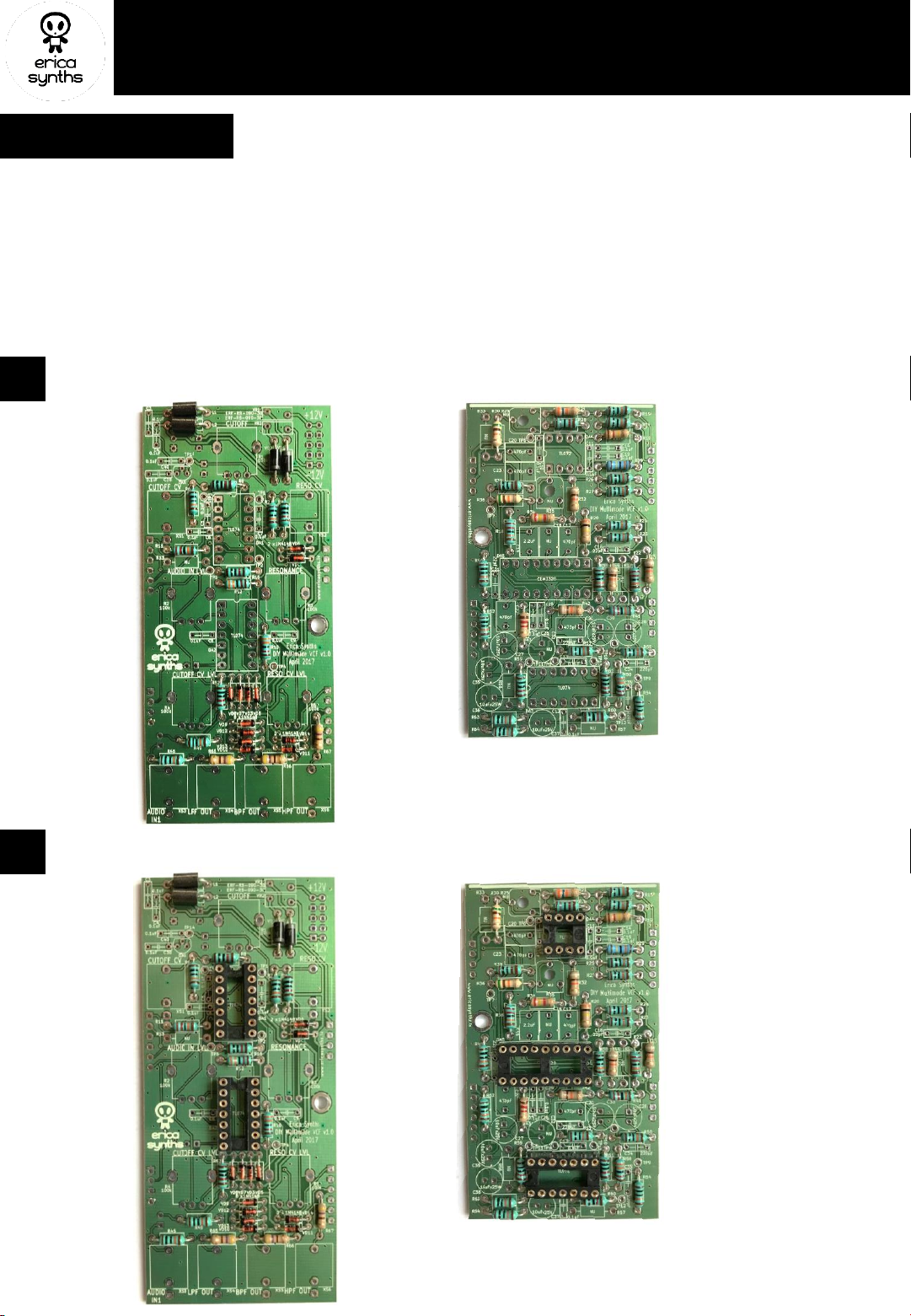
Solder horizontally placed resistors and diodes on both PCBs (Controls board and Main board)! Pay attention on the
orientation of the diodes! Solder the ferrite beads on the controls board!
2
Solder the IC sockets on both boards! Also solder the resettable fuses (if you have rectangular resettable fuses, you
should solder them later on the opposite side of the PCB – they are too high to fit on this side of the board).
GUIDE TO ASSEMBLY OF ERICA SYNTHS MULTIMODE VCF
Controls board
Main board
Page 3
3
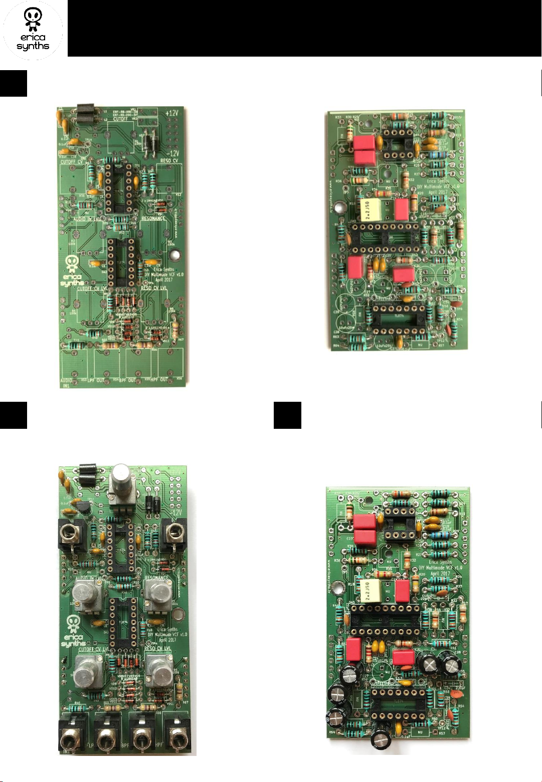
Solder the capacitors on both boards!
4
GUIDE TO ASSEMBLY OF ERICA SYNTHS MULTIMODE VCF
5
Solder the electrolytic capacitors on the Main
board! These are non-polarized capacitors, so
polarity doesn’t matter.
Solder, the voltage regulator, the
potentiometers and jacks on the controls
board!
Page 4
6
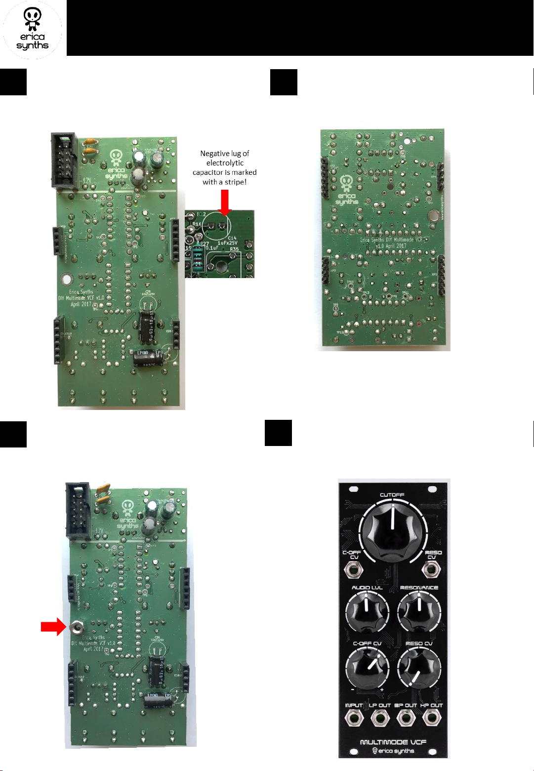
Turn the controls board around and solder the
electrolytic capacitors, the PSU connector, the board
connectors (female) and resettable fuses (round
ones that come with a kit are ok to fit on the top side
of the board).
8
Use the M3x6 screw to attach the spacer to the
Control PCB! Connect both PCBs together and
secure the bottom one with the other M3x6 screw!
For all our modules with 2 PCBs the white stripes on
both PCBs have to match.
9
7
Solder board connectors (male) on the main board!
GUIDE TO ASSEMBLY OF ERICA SYNTHS MULTIMODE VCF
Notice that two
non-polarized
capacitors should
be soldered
horizontally!
Install the front panel and potentiometer knobs!
Congratulations! You have completed the Erica
Synths Multimode VCF module! It does not need
calibration and will work straight away.
 Loading...