

Page 1
START
TRIG A CV1
TRIG B CV1
CV2
CV2 CV3
CV3 OUT A
OUT B
END ATTACK
DATA/ENC TUNE DECAY
SD
A/B
B
A
SAMPLE DRU
B
A
PATTERNBANK
PASTECOPY
CLEARSHIFT
STEP/TAPTRIG SEL
DRCTNSHUFFLE
LAST STEPMUTE
RST CLK OUT GATE LFO2 ACC1 ACC2 ACC3 ACC4 ACC5 ACC6 ACC7 ACC8 ACC9 ACC10 ACC11 ACC12 TR15 TR16
MIDI IN CLK IN CV OUT LFO1 TR1 TR2 TR3 TR4 TR5 TR6 TR7 TR8 TR9 TR10 TR11 TR12 TR13 TR14
TUNE SUBOSC LVL DETUNE
CUTOFF RESONANCE FM LEVEL
CUTOFF CV VCF ENV VCA ENV
VCF WAVE C OFF CV 1V/OCT FM IN
MAIN OUTSQR OUTGATE ACCENT TRI OUT
BPLPSQR
SAW
TRI
CC TRIG CC ACC CC CV MAN
TRIG
RC TRIG RC ACC RC CV OUT
TUNE
BALANCEDECAY CV
CC DECAYRC DECAY
SELECT
TRIG ACC
TUNE CV OUT
TUNE
DECAY CV
DECAY
TONE TONE CV
CH DECAY CV OH DECAY CV
CH TRIG TONE CV
CH DEC CV CH
OUT
OH TRIG
ACC
OH DEC CV OH
OUT
CH DECAY OH DECAY
GAIN 1 GAIN 2
CV LVL 1 CV LVL 2
GAIN
CV1
DRIVE
CV1
DRIVE
CV2
GAIN
CV2
IN 1
OUT 1
IN 2
OUT 2
DRIVE 1 DRIVE 2
MODE 1
MODE 2
PARAM 1 PARAM 1
DRY/WETDRY/WET
CV IN
SELECT
SAVE
SELECT
SAVE
OUT L CV IN OUT L
IN 1 OUT R IN 2 OUT R
PARAM 2PARAM 2
FX1 FX2
A+M
M
A+M
M
A+M
M
IN 1 IN 4
IN 7
IN 2 IN 5 COMP
AMT
IN 3
IN
1 IN 3
IN
2 IN 4
IN
5
IN
6
IN
7 AUX OUT
MAIN
OUT
IN 6 RELEASE
IN 1
IN 6IN 3
IN 1 IN 3 IN 5 A OUT
IN 2 IN 4 IN 6 M OUT
IN 5IN 2
IN 4
A+M
M
A+M
M
A+M
M
PAN 1
IN 2 IN 4
IN 1 IN 3
IN 2LIN 1L IN 3L
IN 4L
OUT R
OUT LIN 2
IN 1R IN 2R IN 3R IN 4R
HI-HATS D
CYBALS
DUAL DRIVE
IXER LITE
0
0
o
5’’
360
o
0
0
o
360
o
SYNC 1 RATE CV 1 OUT o 1 OUT 1
SYNC 2 RATE CV 2 OUT
o
2 OUT 2
RATE 1
FALL/PHASE 2RISE/PHASE 1
SHAPE 2SHAPE 1
RATE 2
ODULATOR
LINK 2
VCA 1
PHASE
TECHNO
SYSTEM
User manual
and
patch book
Page 2
WHAT YOU GET:
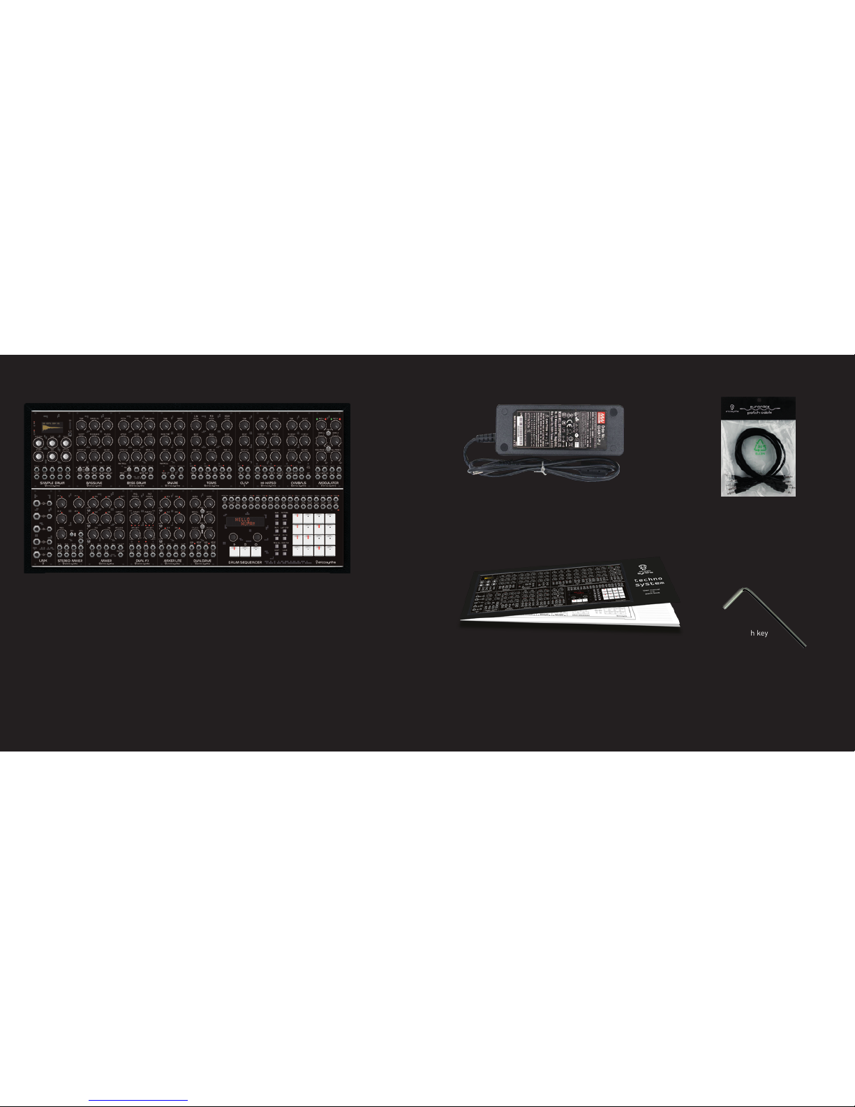
• Erica Synths Techno System in a travelcase with a lid containing 16 modules.
The modules are internally patched to the sequencer, so they receive Trigger and Accent signals
even without patching relevant patch cables.
• External PSU module and mains cable with a connector used in your country.
It’s universal PSU, so you can use it all over the world
only replacing mains cable.
• User manual which contains
pages for your patch notes
• 20 patch cables
• Wrench key
ERICA SYNTHS TECHNO SYSTEM SPECIFICATIONS
Power supply,,,,,,,,,,,,,,,,,,,,,,,,,,universal 110-240VAC - 12VDC adapter
Power consumption..................................................................1,5A
Dimensions (W × D × H)...........................................550x280x140mm
Mass (with lid).............................................7,55 kg (excluding PSU)
Specifications and appearance are subject to change without notice
for improvement.
Page 3

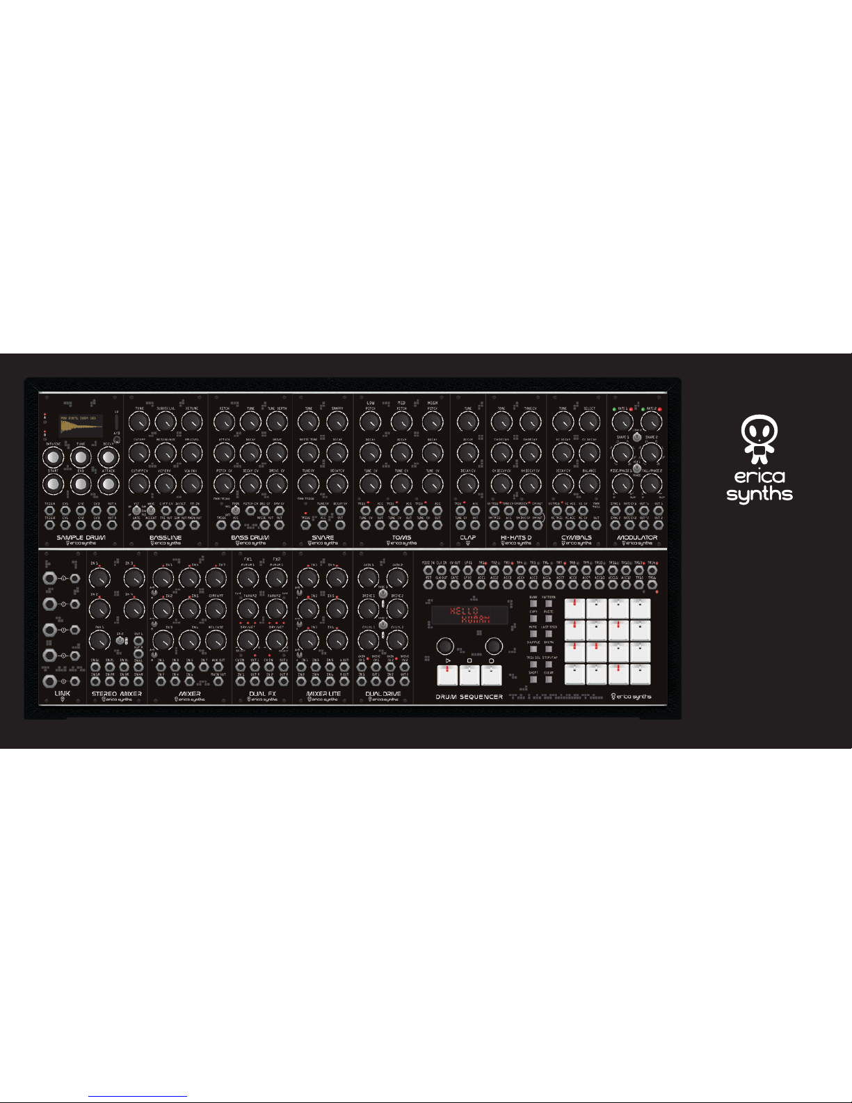
ERICA SYNTHS TECHNO SYSTEM
Thank you for ordering Erica Synths Techno System!
It is the ultimate tool for techno/industrial/dnb production and live performances. With bit of imagination you’ll find that it’s not limited to specific
music genres — it just depends on your creativity in patching, settings of
modules, what samples are used in Sample Drum and how they are triggered. The potential is unlimited!
Erica Synths Techno System contains following modules:
Sample Drum – is the sample player that reads samples from a SD card and allows you to slice
up loops directly in your modular system and rearrange them to taste, add FXes and save
presets for live performances. Thanks to the module’s dual-channel concept, two loops can be
combined. A total of six CV inputs guarantees lively results
Bassline – full analogue synth voice module for ultimate basslines and leads. It features
AS3340 VCO with three waveforms, a filter inspired by Erica Synths Acidbox and unique
features – transistor-based suboscillator and two BBDs that emulate VCO detune.
Bass Drum – takes classical drum machine kick drum sounds to the next level with a modular
functionality - more parameters and CV control.
Snare Drum – 909 inspired sound with with modular functionality in mind – CV controls and
Accents will add lot of expression to your performance
Toms - the module contains Low Tom, Mid Tom and High Tom, each with individual Pitch and
Decay controls and outputs plus CV control over pitch.
Clap - brings classical drum machine sounds in eurorack. Accent and CV control over tune
adds more versatility in sound.
Hi-Hats D – classical Hi-Hats samples are passed thru AS3330 based VCA with adjustable
shape and controlled via envelope generators of unique design. Extra feature is Open HiHat
looping – when it’s on, a certain part of the sample is looped while the envelope decay is on,
thus creating distinct, delay-like effect.
Cymbals – distinct topology digital/analogue module, where cymbal samples are passed thru
AS3330 based VCA and controlled via envelope generators of unique design. The module features
10 sets of custom Crash and Ride cymbal samples with Tune control and individual Decay control.
Modulator features two identical syncable to the BPM LFOs/noise sources with selectable
morphing waveshapes. LFO frequency can be manually adjusted or CV controled, as well as they
provide frequency divisions and multiplications in Sync mode. Each LFO has two outputs —
main one and secondary one with adjustable phase, so you can create evolving modulations
Drum Sequencer is an ultimate modular drum sequencer with 16x trigger outputs, 12x Accent
outputs, 1x CV and Gate track and 2x Synced or free running LFO outputs.
Mixer Lite is a compact 6 input version of a Drum Mixer. Built in vactrol based compressor
settings can be adjusted to a taste via trimpots through the front panel.
Dual Drive features two independent distortion circuits with gain and overdrive parameters,
each with three overdrive flavours. Thanks to CV inputs, it is possible to create very lively
distortion and great stereo effects.
Dual FX combines two Spin FV-1 chips in one module, each filled with eight custom effect
programs with two adjustable and CV controlled parameters per effect and analogue dry/wet
circuit. The effects repertoire of the Dual FX has been specially tailored to drum sounds and all
parameter settings can be saved with the effect.
Drum Mixer – compact, 7 input mixer of unique design provides greater dynamic range and
built in vactrol based compressor for high clarity of each drum sound in the mix. The first three
inputs have selectable allocation - to the Main output or Main output + Aux Send
Stereo Mixer comes equipped with four channel strips, each containing two inputs (L / R).
Thanks to some clever routing options, mono signals can be placed nicely in the panorama as
well. All four stereo channel strips feature a level potentiometer and a limiter provides
protection against very hot signals.
LINK is the module that bridges eurorack to stage mixers — it has 5 sections that attenuate
eurorack signals to line level signals and send them to 6,3mm jacks for quality connection to
the performance mixer.
Please, refer to user manuals for each module below!
Page 4
QUICK STRAT
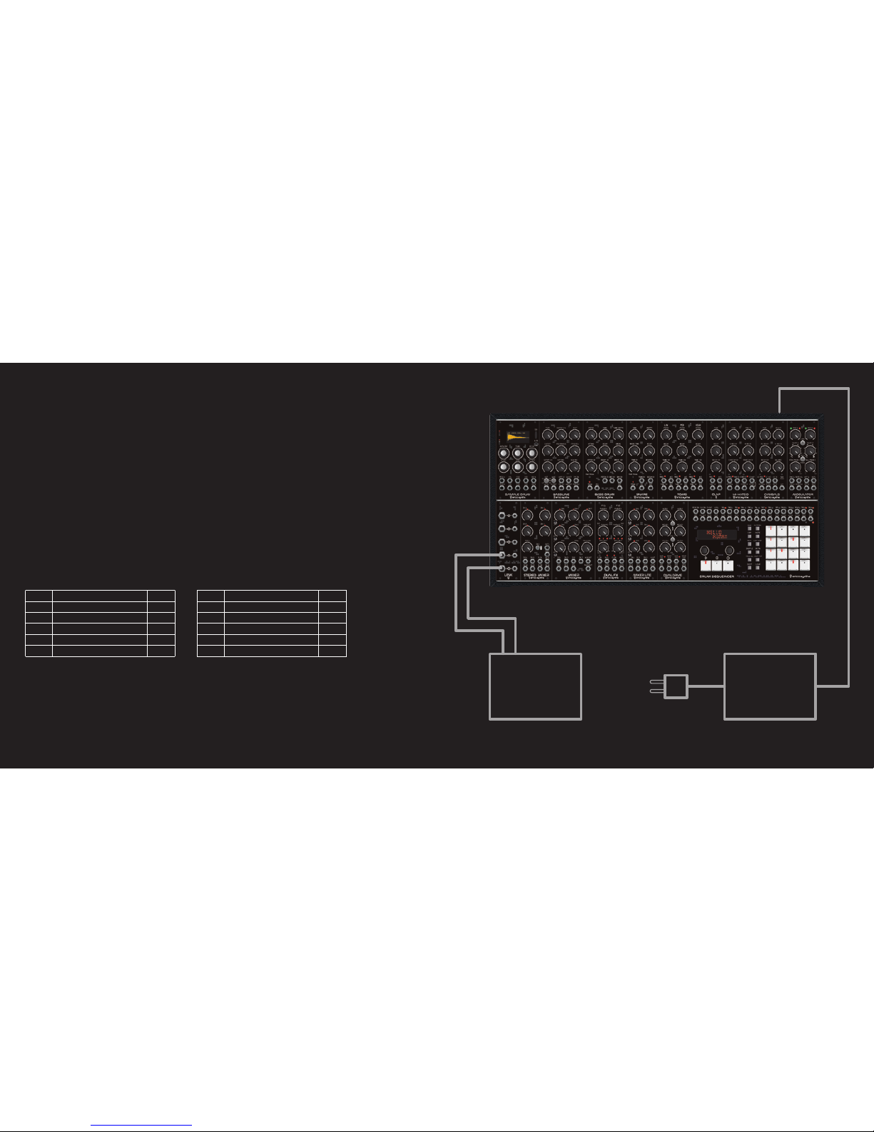
The Techno System is plug and play! Connect the power connector cable, connect
the LINK module to mixing console or amplifier using 6,3mm cables (not supplied
with the Techno System), flip the power switch and start patching!
Note that you can use the internal mixers for mixing sounds, as well as send
individual drums to the mixing console via LINK module.
In order to keep a setup more clean and easy to control, the system comes
internally patched with the Trigger and Accent cables leading from the Sequencer
to the modules, so you must take care only about audio and modulation patch.
Once a trigger is selected, a sequencer will indicate relevant drum voice on the
OLED screen. Nevertheless, you can still use patch cables for triggers and accents.
In that case internal patch will be interrupted and replaced by one with patchcables.
Also if you don't want to see trigger labels, but instead see the trigger channel
you can exit the "Techno System" mode by holding down 13,14,15,16 step keys
while booting up the system.
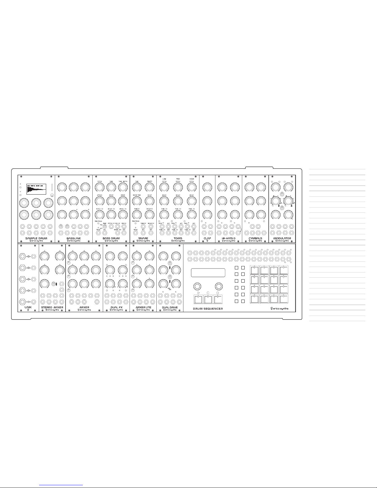
Internal connections and relevant representation on the screen are:
Please, refer to the patch examples below!
Mixer
or
amplifier
External
PSU
TR7 HI TOM HT
TR8 CLAP CP
TR9 CLOSED HAT CH
TR10 OPEN HAT OH
TR11 CRASH CYMBAL CR
TR12 RIDE CYMBAL RD
TR1 BASS DRUM BD
TR2 SNARE DRUM SD
TR3 SAMPLER 1 S1
TR4 SAMPLER 2 S2
TR5 LOW TOM LT
TR6 MID TOM MT
Page 5
TUNE SUBOSC LVL BEEF
CUTOFF RESONANCE FM LEVEL
CUTOFF CV VCF ENV VCA ENV
VCF WAVE C OFF CV 1V/OCT FM IN
MAIN OUTSQR OUTGATE ACCENT TRI OUT
BPLPSQR
SAW
TRI
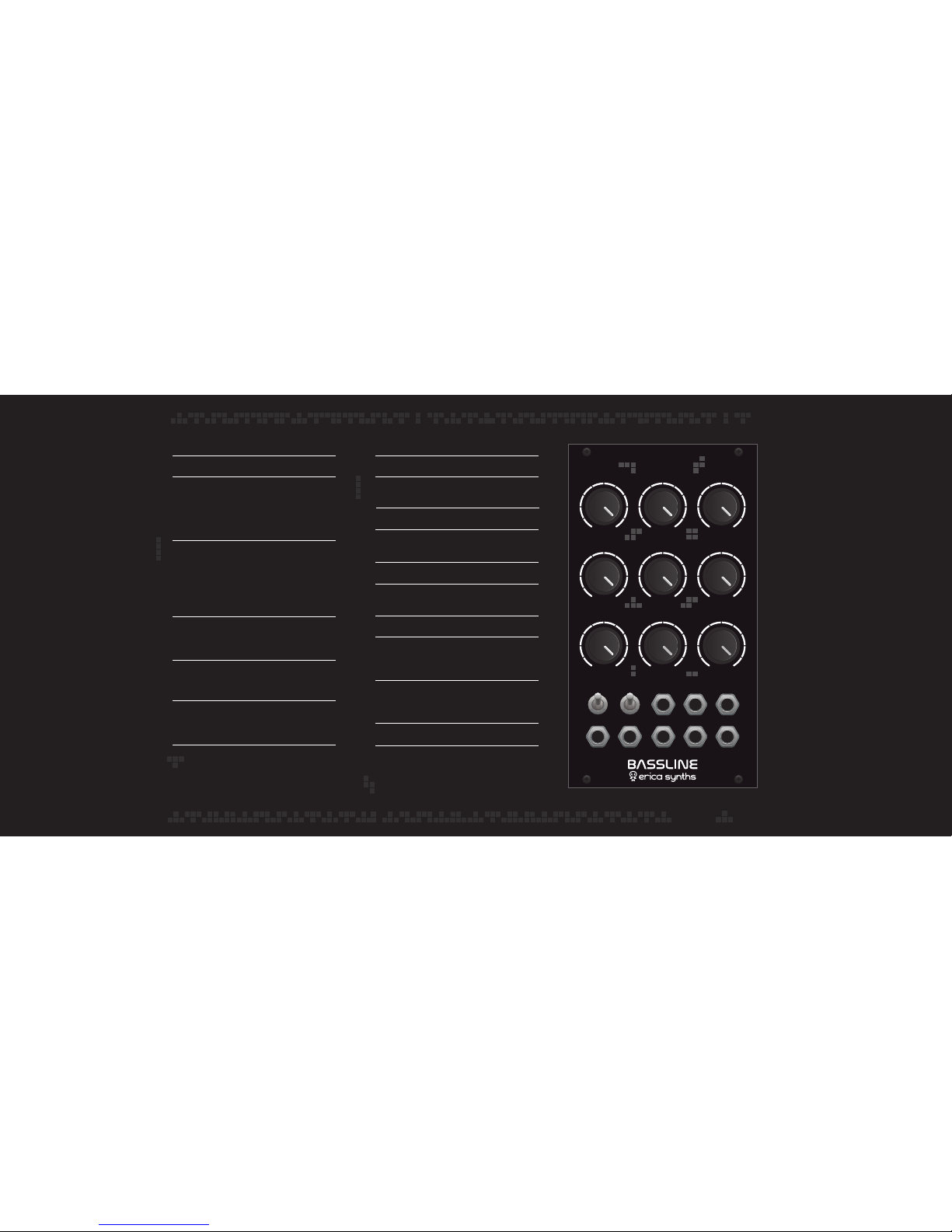
Set the initial tune of the VCO
Add some power to the sound! Turning the
suboscillator level knob CW simultaneously adds
one octave down transistor-based suboscillaotr and
opens dedicated LP filter, so the suboscillator fades in
gently and reveals its real character at full CW setting
Detune function emulates sound of the synh with
several detuned VCOs. Two BBD lines act as a frequency
shifter and a resulting signal is mixed with the original
one. Turning the Detune knob CW also increases
frequency of the LFO that controls BBD lines, so at full
CW setting you get quite an FM madness
Control the VCF cutoff manually. With cutoff CV applied
(from VCF envelope and/or external), you’ll need to
adjust initial cutoff for acid bassline sweetspots
Adjust the VCF resonance! The filter used in the
module is the same as on AcidboxIII, and it’s capable of
extreme resonance sweeps. Mind your speakers!
This is external FM level attenuator. You can also do
some self-modulation by patching TRI OUT in to FM IN
and increasing FM level. Enjoy!
Adjust VCF cutoff CV level! If nothing is patched in C OFF
CV
input, it adjusts VCF envelope impact on the cutoff
TUNE
SUBOSC LVL
DETUNE
CUTOFF
RESONANCE
FM LEVEL
CUTOFF CV
VCF ENV
C OFF CV
1V/OCT
FM IN
GATE
ACCENT
MAIN OUT
TRI OUT
VCF
WAVE
VCA ENV
Adjust the VCF cutoff envelope decay time
Adjust the VCA envelope decay time. Full CW setting
will open the VCA even the gate is not present
Select the VCF mode
Select the VCO waveform that is sent to the master
output
This is an external CV input to control the VCF cutoff
This is the VCO 1V/oct input. It tracks well over
9 octaves
This is the VCO FM input
This is the Gate input. It accepts gate from any
sequencer and sends it to the VCF and VCA
envelopes simultaneously
This is the Accent input. +10V CV will increase the
volume and open the VCF slightly to an expression
to the bassline
This is the main output of the module
These are additional VCO outputs, and they are not
affected by VCF and VCA. You can use them as
additional sound sources that are in tune with your
bassline
Page 6
MODE
NOISE OUT
TRIG
GATE
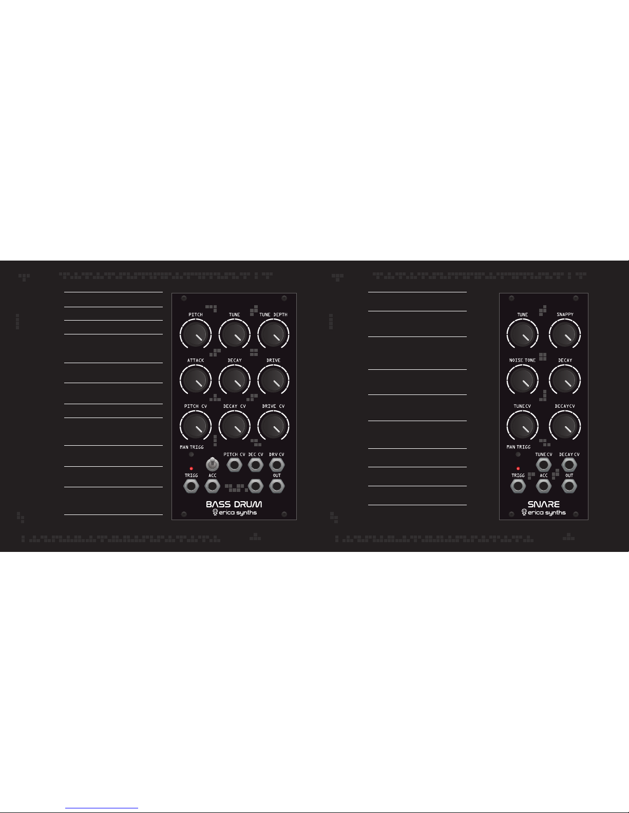
Set master tune of the Snare drum
This knob adjusts noise filter cutoff,
so you can set desired noise tone
Use the manual trigger button to check
the snare drum settings and add
some triggers during live performance
This is trigger input. The LED indicate
incoming trigger
This is the Accent input. +10V CV will set
the Snare Drum to the maximum volume
Snappy knob allows you to fade
between tone and noise
Set the decay time of the noise
,
These are CV attenuators of relevant CV inputs
These are CV inputs to control Tune and Decay
This is the output of the module
TUNE
NOISE TONE
MAN TRIGG
TRIGG
ACC
SNAPPY
DECAY
TUNE CV, DECAY CV
TUNE CV IN, DECAY CV IN
OUT
Set master pitch of the Bass drum
Set decay time of the pitch envelope
Adjust the depth of pitch envelope
Set the volume envelope attack time.
Like on the classical drum machines full
CW setting gives the sharpest attack
Set the volume envelope decay time from
very short to overlapping base roars
Adjust the overdrive level of the
drum sound form none to extreme
These are CV attenuators of relevant CV inputs
Use the manual trigger button
to check the bass drum settings and
add some beats during live performance
These are CV inputs to control
Pitch, Decay and Drive
This is the Trigger input
The LED indicates incoming triggers
This is the Accent input. +5V CV will
increase the volume of the drum and add
an expression to the bassdrum track
This is the output of the module
PITCH
TUNE
TUNE DEPTH
ATTACK
DECAY
DRIVE
DECAY CV
MAN TRIGG
DECAY CV
TRIGG
ACC
OUT
Page 7
TRIG ACC
TUNE CV OUT
TUNE
DECAY CV
DECAY
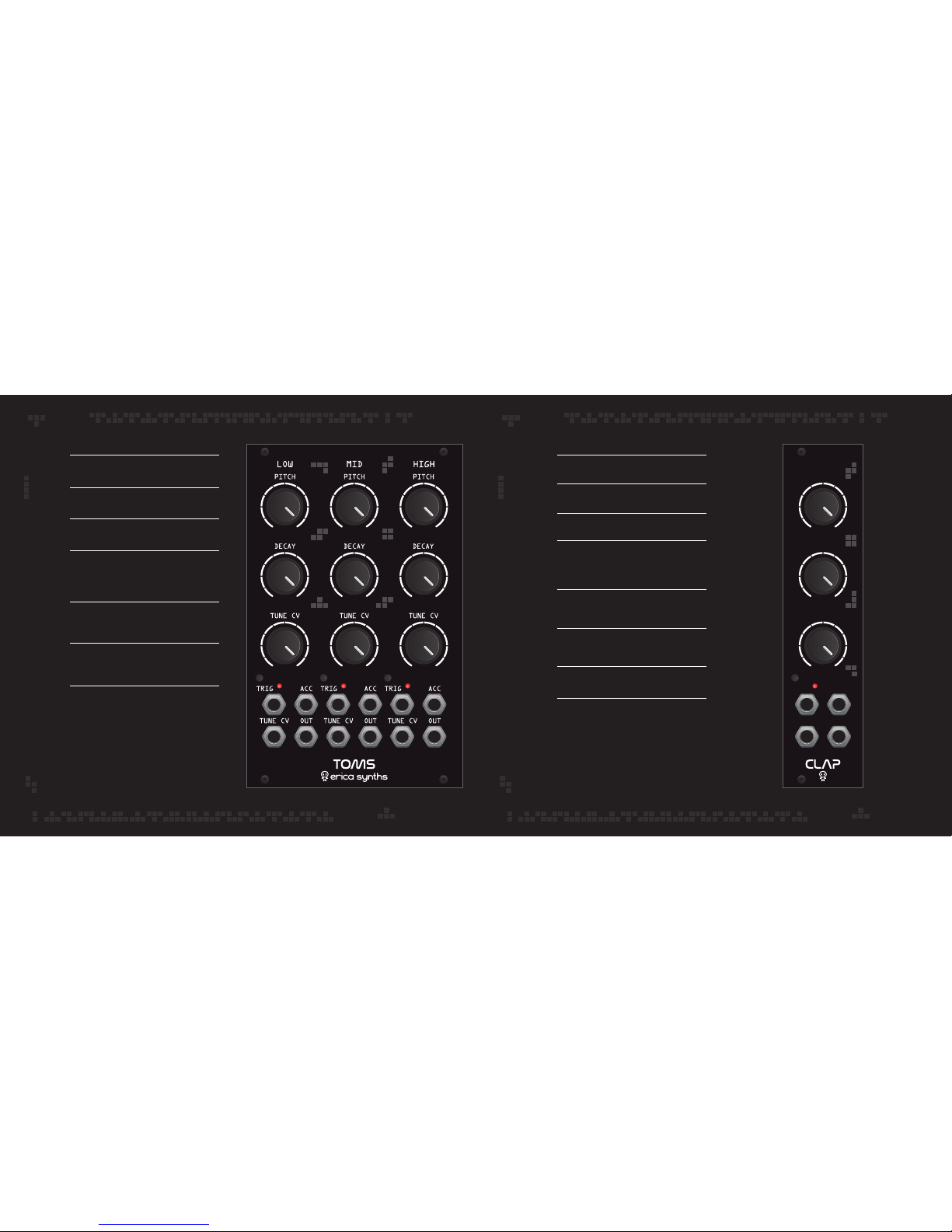
Set master tone of the Clap
Set the decay time of the clap noise
This is Tone CV attenuator
Use the manual trigger button to check
the clap settings and add some beats
during live performance
This is the Trigger input. The LED indicates
incoming triggers
This is the Accent input. +10V CV will set
the Clap to the maximum tone
This is Tone CV input
This is the output of the module
TONE
DECAY
TONE CV
TRIG
TRIGG IN
ACC
TONE CV
OUT
Set the initial pitch of each Tom manually!
Adjust decay time of each Tom
These are pitch CV attenuators
Use the manual trigger buttons to check
the toms settings and add some triggers
during live performance
These are the Trigger inputs.
The LEDs indicate incoming triggers
These are the Accent inputs. +10V CV will
set the tom to the maximum volume.
These are the outputs of each tom
PITCH
DECAY
PITCH CV
TRIG
TRIG IN
ACC
OUT
Page 8
TONE TONE CV
CH DECAY CV OH DECAY CV
CH TRIG TONE CV
CH DEC CV CH
OUT
OH TRIG
ACC
OH DEC CV OH
OUT
CH DECAY OH DECAY
HI-HATS D
CC TRIG CC ACC CC CV MAN
TRIG
RC TRIG RC ACC RC CV OUT
TUNE
BALANCEDECAY CV
CC DECAYRC DECAY
SELECT
CYBALS
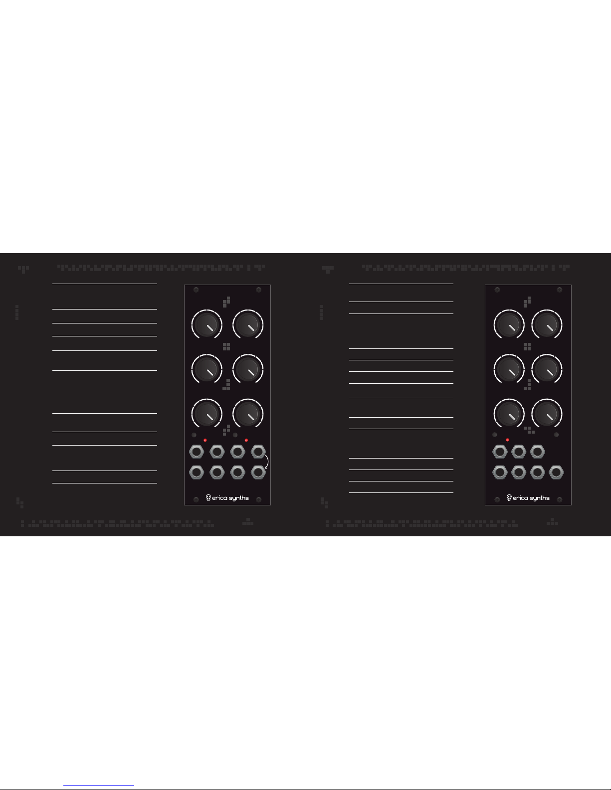
Set the master Tune of Hi-Hats. This affects
both Hi-Hats simultaneously, and essentially
controls the sample playback rate
This is Tune CV level attenuator
Adjust Closed hat decay time manually
Adjust Open hat decay time manually
This is Decay CV level attenuator. It effects both
HiHats simultaneously
Adjust the VCA response from sharp, aggressive
full CCW (logarithmic setting) to smooth and
long decays full CW (linear setting)
Use the manual trigger buttons to check the Hi-Hats
settings and add some beats during live performance
These are Trigger inputs. The LEDs
indicate incoming triggers
This is Tune CV input
This is the Accent input. +10V CV will set
the Hi-Hats to the maximum volume, and
it affects both Hi-Hats simultaneously
This is Decay CV input
This is the output of the module. Note that you can’t
play both HiHats simultaneously. The Open HiHat
has priority over the Closed one
TUNE
TUNE CV
CH DECAY
OH DECAY
DECAY CV
VCA SHAPE
CH TRIG, OH TRIG
TUNE CV
DEC CV
ACC
OUT
Set the master Tune of Cymbals. This affects both Cymbals
simultaneously, and essentially controls the sample playback rate
Select one of 10 sets of Cymbal samples
These are cymbal “looping”switches. When they are on,
after initial hit, a certain portion of the sample starts to loop
during envelope generator decay until the VCA closes
completely. This creates a feeling of delay applied to the
cymbal. Note that looping works the best on long decay.
Adjust Crash Cymbal decay time manually
Adjust Ride Cymbal decay time manually
This is Tune CV level attenuator
This is Decay CV level attenuator. It effects both
Cymbals simultaneously
Use the manual trigger buttons to check the Cymbal
settings and add some beats during live performance
This is Tune CV input
This is the Accent input. +10V CV will set the Cymbals
to the maximum volume, and it affects both Cymbals
simultaneously. The accent sensitivity is adjustable –
please, refer to instructions in this manual
These are Trigger inputs. The LEDs indicate incoming triggers
These are Decay CV inputs
This is Crash Cymbal output
This is Ride Cymbal output and the Main output of the
module – when nothing is patched in the Crash Cymbal
output, it’s automatically mixed to the Ride Cymbal output
TUNE
SELECT
CRASH LOOP, RIDE LOOP
CRASH DECAY
RIDE DECAY
TUNE CV
DECAY CV
TUNE CV
CR TRIG, RD TRIG
CR D CV, RD D CV
CR OUT
ACC
RD OUT
Page 9
0
0
o
5’’
360
o
0
0
o
360
o
SYNC 1 RATE CV 1 OUT o 1 OUT 1
SYNC 2 RATE CV 2 OUT
o
2 OUT 2
RATE 1
FALL/PHASE 2RISE/PHASE 1
SHAPE 2SHAPE 1
RATE 2
ODULATOR
LINK 2
VCA 1
PHASE
PAN 1
IN 2 IN 4
IN 1 IN 3
IN 2LIN 1L IN 3L
IN 4L
OUT R
OUT LIN 2
IN 1R IN 2R IN 3R IN 4R
RATE
RATE1, RATE2
LINK2
SHAPE1, SHAPE2
RISE; PHASE1
FALL; PHASE2
SYNC1, SYNC2
OUT˚1, OUT˚2
RATE CV1, RATE CV2
OUT1, OUT2
VCA1
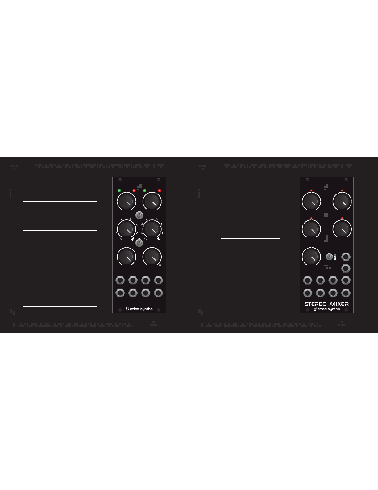
Bicolour LEDs give visual feedback on the output status – the left LED indicates
phase shifted output, the right one – the main output. Red is -5V, green is +5V
Set the initial LFO rate manually. When in SYNC mode this knob becomes a
divider (/2, /4, /8 when turned CCW) or a multiplier (x2, x4, x8, when turned
CW); at 12 o’clock setting the LFO rate will follow incoming clock signal
The switch in upper position “links” LFO2 frequency to the LFO1. The RATE2
knob becomes frequency divider and multiplier. If LFO2 is in Sync mode and the
LINK2 switch is engaged, the incoming sync signal is ignored
Select the waveform! Waveforms are morphed, so turning the knob, you’ll get
interesting in-between waveforms. A full CV setting is pitched noise. The pitch can
be controlled via RATE1 and RATE 2 knobs correspondingly as well as RATE CV
The switch in VCA1 position applies the built in VCA to the output of LFO1,
meaning – it alters the output signal amplitude depending on RISE and FALL
settings. The switch in PHASE setting allows you to adjust phase shift of the
LFO signal on the OUT
0
1. Both effects can be used simultaneously, meaning,
you can set the phase shift and then apply amplitude modulation to the LFO1
This knob has three functions: Adjust VCA envelope RISE time from 0 to 5”;
Adjust phase shift on the OUT 0 1 from 0 0 to 360 0; Adjust lowpass (CCW from 12:00)
or highpass (CW form 12:00) filter cutoff frequency to the noise on the OUT
0
1. If
you want to omit the VCA effect on the LFO1, set this knob all way CCW
This knob has three functions: Adjust VCA envelope FALL time from 0 to
infinity; Adjust phase shift on the OUT
0
2 from 0 0 to 360 0; Adjust lowpass (CCW
from 12:00) or highpass (CW form 12:00) filter cutoff frequency on the OUT
0
2
If you want to omit the VCA effect on the LFO1, set this knob all way CW
These are SYNC inputs. When any clock signal is patched here, the LFO will
automatically sync the frequency to the clock. Please, avoid shuffling clocks
These are phase shifted outputs
These are LFO/noise rate CV inputs. They are automatically disactivated
when the sync signal is applied
These are main outputs
IN1 – IN4 potentiometers adjust
signal level on relevant inputs.
LEDs give visual feedback on signal level
after input potentiometers. LEDs lit when
signal reaches 5Vptp
Input 1 has a panning option –
when mono signal is patched in IN1 L,
use PAN1 knob to adjust IN 1 place in
the stereo image. Same works with
a stereo signal applied on IN1.
IN2 is configurable via switch. S is regular
stereo setting, +6 setting boosts the incoming
signal by +6dB. M setting routes IN2 L and
IN2 R signals to both stereo channels,
meaning you get two mono inputs with
a single volume control
These are the Audio inputs. If only Left input
is used, signal is automatically normalled to
the Right channel
These are Left and Right outputs of the mixer
IN1–IN4
PAN 1
IN2
IN
OUT L& OUT R
Page 10
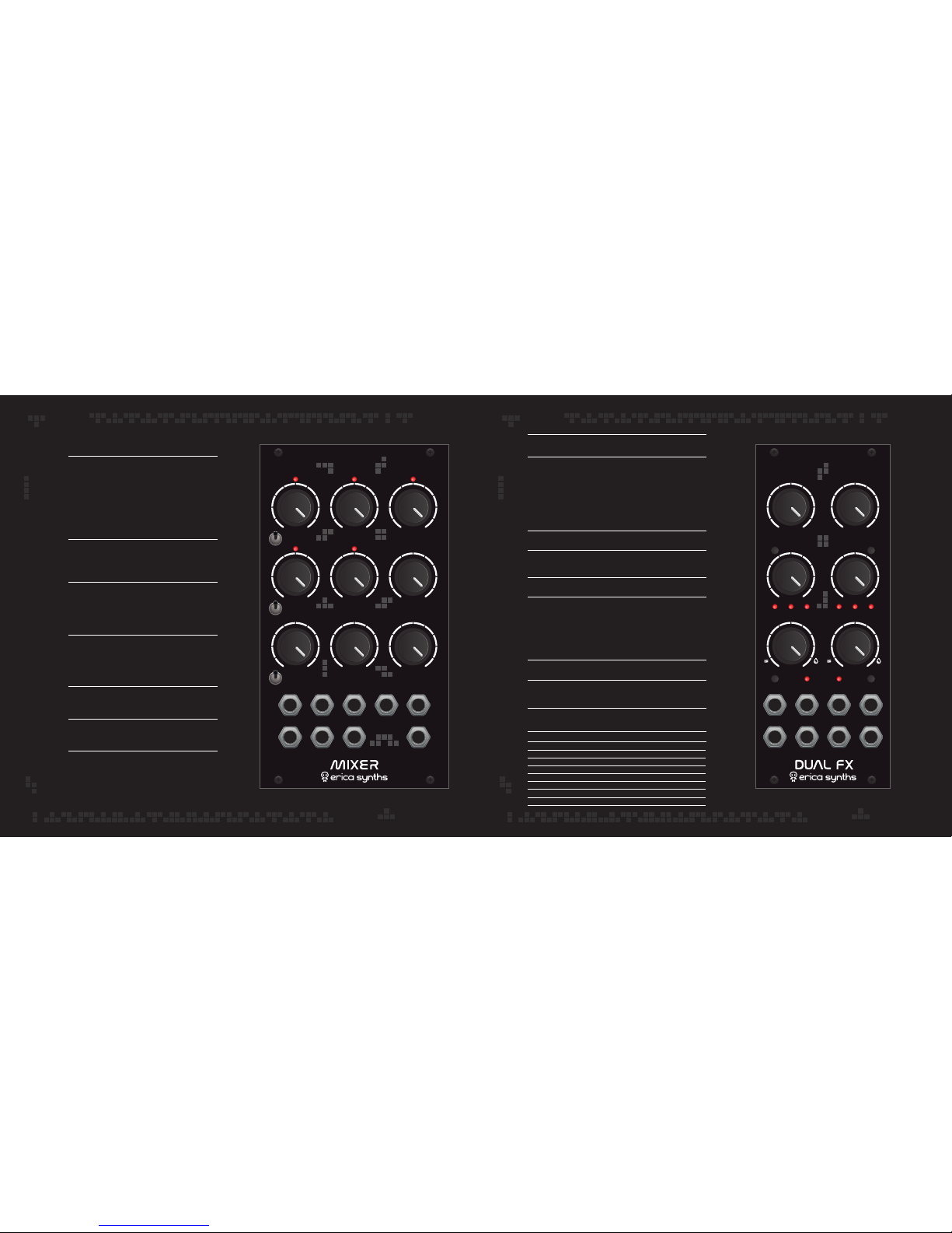
A+M
M
A+M
M
A+M
M
IN 1 IN 4
IN 7
IN 2 IN 5 COMP
AMT
IN 3
IN
1 IN 3
IN
2 IN 4
IN
5
IN
6
IN
7 AUX OUT
MAIN
OUT
IN 6 RELEASE
PARAM 1 PARAM 1
DRY/WETDRY/WET
CV IN
SELECT
SAVE
SELECT
SAVE
OUT L CV IN OUT L
IN 1 OUT R IN 2 OUT R
PARAM 2PARAM 2
FX1 FX2
PARAM 1
SAVE
LEDs
PARAM 2
DRY/WET
SELECT
CV IN
IN 1
OUT L, OUT R
Adjust the first parameter of the effect
Push and hold the SAVE button for 2" to save the parameter and
dry/wet settings with the effect. To recall parameter and dry/wet
settings, push the SAVE button promptly. All three effect select
LEDs will blink once to confirm setting recall. Now, if you turn
the parameter knobs to alter the settings, the LEDs will flash
once, when the saved position of the potentiometer is reached.
Only then parameter changes will take effect.
Adjust the second parameter of the effect
These are the effect indicator LEDs. They indicate one of 8 selected
effects in binary code. Please, refer to the Effect table below!
This is dry/wet control potentiometer
This is effect select button. Push it promptly to navigate thru effects.
To assign CV input to control one of the parameters or dry/wet setting,
push and hold the button for 2”. The first effect indicator LED will start
to flash, indicating that the CV is assigned to the first parameter. Push
the button repeatedly to assign the CV input to the 2nd effect or to
dry/wet control.Push the SAVE button to confirm
This is the assignable CV input
This is the audio input. The effects are designed to add
stereo spread to the mono input signal
These are left and right outputs. We highly recommend
to use the module with the stereo mixer
FX DRY/WET PARAM 1 PARAM 2
MONO DELAY
STEREO DELAY
HI PASS DELAY
BIG REVERB
SATURATED REVERB
STALKER REVERB
RIPPER
DUAL PITCH SHIFTER
DRY/WET
DRY/WET
DRY/WET
DRY/WET
DRY/WET
DRY/WET
DRIVE
DRY/WET
TIME
TIME
TIME
SIZE
SIZE
TONE
CRUSH
SHIFT 1
FEEDBACK
FEEDBACK
HI PASS FILTER
TONE
TONE
FEEDBACK
DELAY TIME
SHIFT 2
IN1 – IN7 potentiometers adjust signal
level on relevant inputs.
LEDs give visual feedback on signal level
after input potentiometers. LEDs lit when
signal reaches 5Vptp
Use switches to assign the first three inputs
to Main or to both Main and Aux Send outputs
These are the Audio inputs. The input signal
can be boosted for +6dB with the level
potentiometer knobs full CW
Adjust compression amount to your taste!
Note that maximum compression amount
settings may result in more noisy output
Adjust compressor release time to your taste!
This is the effects send output
This is the main output of the mixer
IN1–IN7
A+M
IN
AUX OUT
MAIN OUT
COMP AMT
RELEASE
Page 11
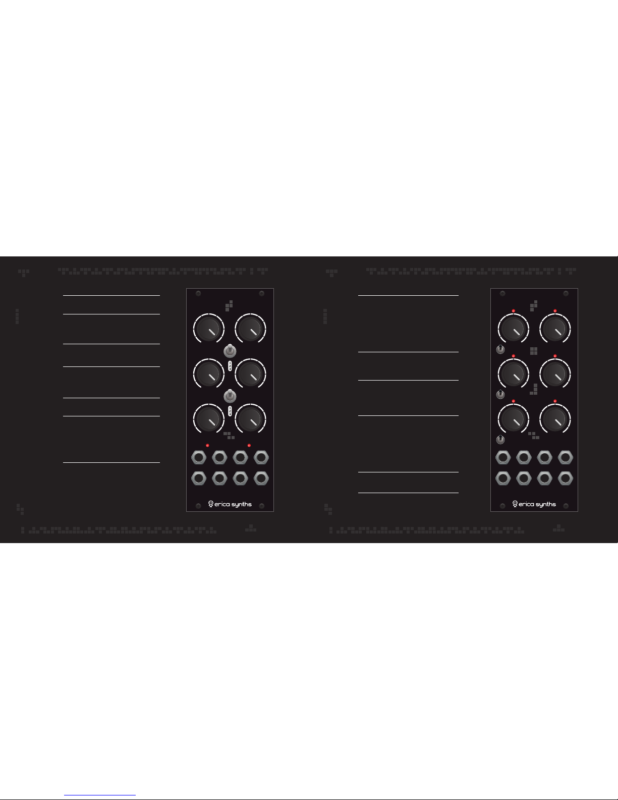
GAIN 1 GAIN 2
CV LVL 1 CV LVL 2
GAIN
CV1
DRIVE
CV1
DRIVE
CV2
GAIN
CV2
IN 1
OUT 1
IN 2
OUT 2
DRIVE 1 DRIVE 2
MODE 1
MODE 2
DUAL DRIVE
IN 1
IN 6IN 3
IN 1 IN 3 IN 5 A OUT
IN 2 IN 4 IN 6 M OUT
IN 5IN 2
IN 4
A+M
M
A+M
M
A+M
M
IXER LITE
Adjust Gain for the each section manually
Mode switch allows you to select one
of three overdrive flavours – it connects
drive circuits in several combinations
Adjust overdrive level for each
section manually
These are CV level attenuators. Note that
they affect both CV (Gain and Drive) inputs
simultaneously
These are Gain and Drive CV inputs
IN1 and IN2 are audio inputs of both overdrive
sections. Please note, that if nothing is patched
in IN2, it is normalled to OUT1 and both sections
automatically are connected in series
LEDs give visual feedback on overdrive level
These are outputs of both overdrive sections
GAIN1, GAIN2
MODE1, MODE2
DRIVE1, DRIVE2
CV LVL 1, CV LVL 2
GAIN CV IN, DRIVE CV IN
IN 1, IN 2
OUT 1, OUT 2
IN1 – IN6 potentiometers adjust
signal level on relevant inputs.
LEDs give visual feedback on signal level
after input potentiometers. LEDs lit when
signal reaches 5Vptp
Use switches to assign the first three inputs
to Main or to both Main and Aux Send outputs
These are the Audio inputs. The input
signal can be boosted for +6dB with the level
potentiometer knobs full CW
Use a small screwdriver to access the
top trimmer potentiometer and set the compression
amount to your taste! Note that maximum
compression amount settings may result
in more noisy output. The bottom trimmer
potentiometer adjusts compressor release.
This is the effects send output
This is the main output of the mixer
IN1–IN6
A+M
IN
TRIMMER POTENTIOMETERS
A OUT
M OUT
Page 12
Page 13
Page 14
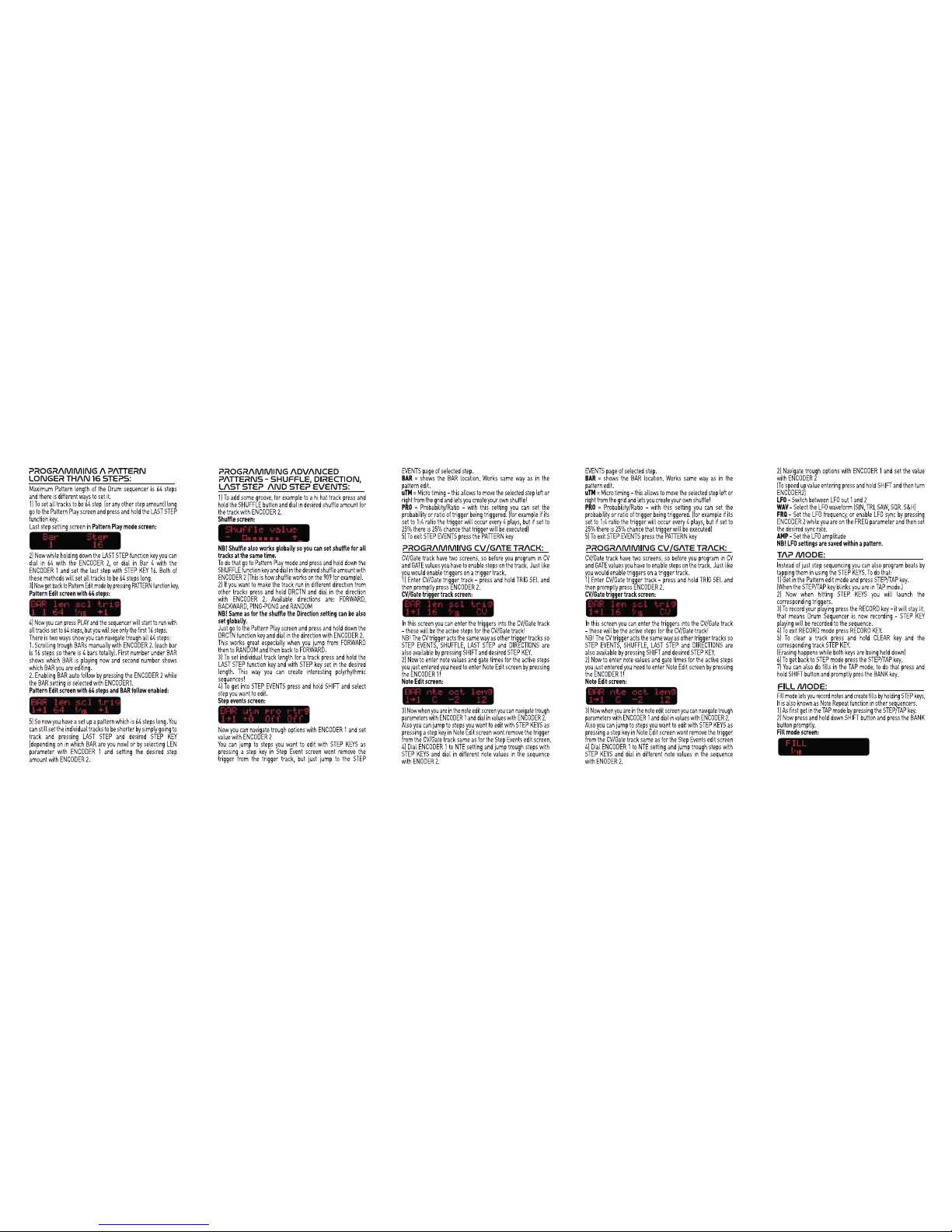
Page 15
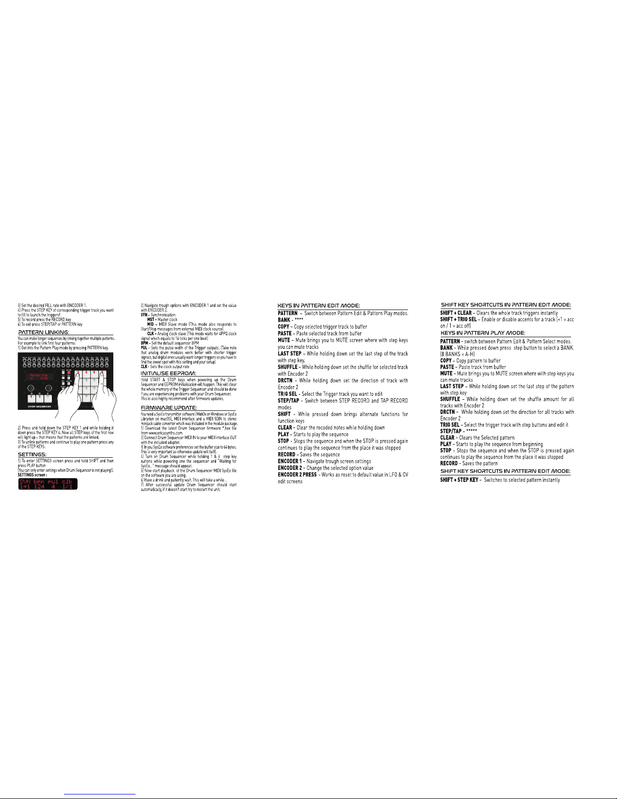
Page 16
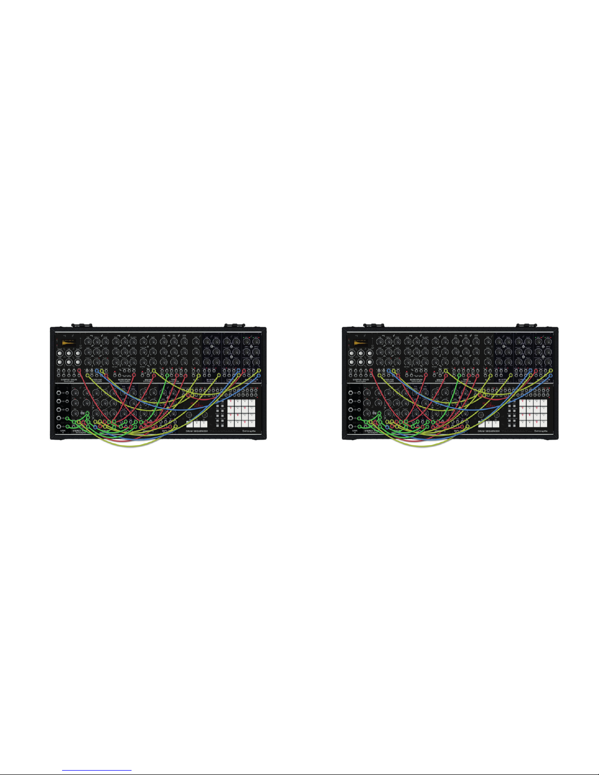
PATCH EXAMPLE 2PATCH EXAMPLE 1
Page 17

DISPOSAL
Please follow the instructions for use of the Erica Synths Techno System below, ‘cause
only this will guarantee proper operation of the module and ensure warranty from Erica
Synths.
Use Erica Synths Techno System exclusively with the power supply unit (PSU) supplied
with the system. Powering it with other PSU units may cause permanent damage of the
device.
Water is lethal for most of the electric devices, unless they are made waterproof. Erica
Synths Techno System is NOT intended for use in a humid or wet environment. No liquids
or other conducting substances must get into the module. Should this happen, the
module should be disconnected from mains power immediately, dried, examined and
cleaned by a qualified technician.
Do not expose the module to temperatures above +50° C or below -20° C. If you have
transported the system in extreme low temperatures, leave it in room temperature for an
hour before plugging it in.
Transport the instrument carefully, never let it drop or fall over. Warranty does not apply
to modules with visual damages.
The system has to be shipped in the original packaging only. Any system shipped to us for
return, exchange and/or warranty repair has to be in its original packaging. All other
deliveries will be rejected and returned to you. Make sure you keep the original
packaging and technical documentation.
You will find Erica Synths terms of warranty at www.ericasynths.lv.
Items for return, exchange and/or warranty repair have to be sent to:
Erica Synths, Andrejostas Str. 143, Riga, Latvia, LV-1045
This device complies to the EU guidelines and is manufactured RoHS conforming without
use of led, mercury, cadmium and chrome. Nevertheless, this device is special waste and
disposal in household waste is not recommended.
User manual by Girts Ozolins@Erica Synths .
Design by Edmunds Pavlovskis.
Copying, distribution or any commercial use in any way is prohibited and needs the
written permission by Erica Synths.
Specifications are subject to change without notice.
In case of any questions, feel free to contact us through
www.ericasynths.lv or via e-mail
[email protected].
SAFETY INSTRUCTIONS
Page 18
START
TRIG A CV1
TRIG B CV1
CV2
CV2 CV3
CV3 OUT A
OUT B
END ATTACK
DATA/ENC TUNE DECAY
SD
A/B
B
A
PATTERNBANK
PASTECOPY
CLEARSHIFT
STEP/TAPTRIG SEL
DRCTNSHUFFLE
LAST STEPMUTE
RSTCLK OUTGATELFO2ACC1ACC2ACC3ACC4ACC5ACC6ACC7ACC8ACC9ACC10ACC11ACC12TR15TR16
MIDI INCLK INCV OUTLFO1TR1TR2TR3TR4TR5TR6TR7TR8TR9TR10TR11TR12TR13TR14
TUNE SUBOSC LVL DETUNE
CUTOFF RESONANCE FM LEVEL
CUTOFF CV VCF ENV VCA ENV
VCF WAVE C OFF CV 1V/OCT FM IN
MAIN OUTSQR OUTGATE ACCENT TRI OUT
BPLPSQR
SAW
TRI
CC TRIG CC ACC CC CV MAN
TRIG
RC TRIG RC ACC RC CV OUT
TUNE
BALANCEDECAY CV
CC DECAYRC DECAY
SELECT
TRIG ACC
TUNE CV OUT
TUNE
DECAY CV
DECAY
TONE TONE CV
CH DECAY CV OH DECAY CV
CH TRIG TONE CV
CH DEC CV CH
OUT
OH TRIG
ACC
OH DEC CV OH
OUT
CH DECAY OH DECAY
GAIN 1 GAIN 2
CV LVL 1 CV LVL 2
GAIN
CV1
DRIVE
CV1
DRIVE
CV2
GAIN
CV2
IN 1
OUT 1
IN 2
OUT 2
DRIVE 1 DRIVE 2
MODE 1
MODE 2
PARAM 1 PARAM 1
DRY/WETDRY/WET
CV IN
SELECT
SAVE
SELECT
SAVE
OUT L CV IN OUT L
IN 1 OUT R IN 2 OUT R
PARAM 2PARAM 2
FX1FX2
A+M
M
A+M
M
A+M
M
IN 1 IN 4
IN 7
IN 2 IN 5 COMP
AMT
IN 3
IN
1 IN 3
IN
2 IN 4
IN
5
IN
6
IN
7 AUX OUT
MAIN
OUT
IN 6 RELEASE
IN 1
IN 6IN 3
IN 1 IN 3 IN 5 A OUT
IN 2 IN 4 IN 6 M OUT
IN 5IN 2
IN 4
A+M
M
A+M
M
A+M
M
PAN 1
IN 2 IN 4
IN 1 IN 3
IN 2LIN 1L IN 3L
IN 4L
OUT R
OUT LIN 2
IN 1R IN 2R IN 3R IN 4R
0
0
o
5’’
360
o
0
0
o
360
o
SYNC 1 RATE CV 1 OUT o 1 OUT 1
SYNC 2 RATE CV 2 OUT
o
2 OUT 2
RATE 1
FALL/PHASE 2RISE/PHASE 1
SHAPE 2SHAPE 1
RATE 2
LINK 2
VCA 1
PHASE
 Loading...