

Ergotron WorkFit-S, WorkFit-T, WorkFit-PD User Manual
888-33-332-W-02 rev.G • 11/15
1 of 12
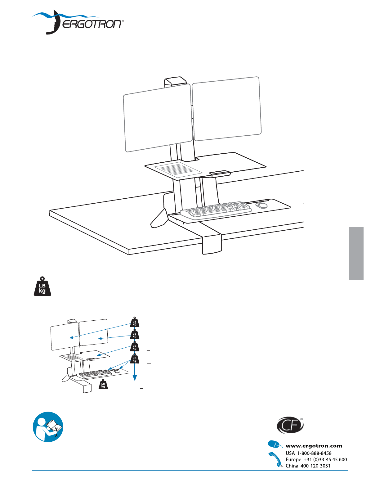
WorkFit-S, Dual
A 6 - 14 lbs (2.7-6.4 kg)
B 6 - 14 lbs (2.7-6.4 kg)
C < 5 lbs (2.3 kg)
A+B+C+D
< 25 lbs (11.3 kg)
D < 5 lbs (2.3 kg)
Includes
Constant Force™
Technology
User's Guide - English
Guía del usuario - Español
Manuel de l’utilisateur - Français
Gebruikersgids - Deutsch
Benutzerhandbuch - Nederlands
Guida per l’utente - Italiano
Användarhandbok - svenska
ユーザーガイド:日本語
用户指南 : 汉语
ENGLISH
For the latest User Installation Guide please visit: www.ergotron.com
User's Guide
CAUTION: DO NOT EXCEED MAXIMUM LISTED
WEIGHT CAPACITY. SERIOUS INJURY OR
PROPERTY DAMAGE MAY OCCUR!

888-33-332-W-02 rev.G • 11/15
2 of 12
ENGLISH
These symbols alert users of a safety condition that demands attention. All users should
be able to recognize and understand the
signifi cance of the following Safety Hazards
if encountered on the product or within the
documentation. Children who are not able
to recognize and respond appropriately to
Safety Alerts should not use this product without adult supervision!
Hazard Symbols
Review
Symbol Signal Word Level of Hazard
NOTE
A NOTE indicates important information that helps you
make better use of this product.
CAUTION
A CAUTION indicates either potential damage to
hardware or loss of data and tells you how to avoid the
problem.
WARNING
A WARNING indicates either potential for property damage, personal injury, or death.
ELECTRICAL
An Electrical indicates an impending electrical hazard
which, if not avoided, may result in personal injury, re
and/or death.
Safety
Important! You will need to adjust this product after installation is complete. Make sure all your equipment
is properly installed on the product before attempting adjustments. This product should move smoothly
and easily through the full range of motion and stay where you set it. If movements are too easy or
diffi cult or if product does not stay in desired positions, follow the adjustment instructions to create
smooth and easy movements. Depending on your product and the adjustment, it may take many turns to
notice a difference. Any time equipment is added or removed from this product, resulting in a change in
the weight of the mounted load, you should repeat these adjustment steps to ensure safe and optimum
operation.
Warning: Because mounting surface materials can vary widely, it is imperative that you make sure mounting surface is strong
enough to handle mounted product and equipment.
Caution:
To avoid the potential to pinch cables it is important to follow the cable routing instructions in this manual. Failure to follow
these instructions may result in equipment damage or personal injury.
CAUTION! Tipping Hazard. Support the stand until the clamp is securely tightened. Failure to follow these
instructions may result in the stand tipping over causing possible equipment damages and or personal injury.
888-33-332-W-02 rev.G • 11/15
3 of 12
1
2
4
12
11
ENGLISH
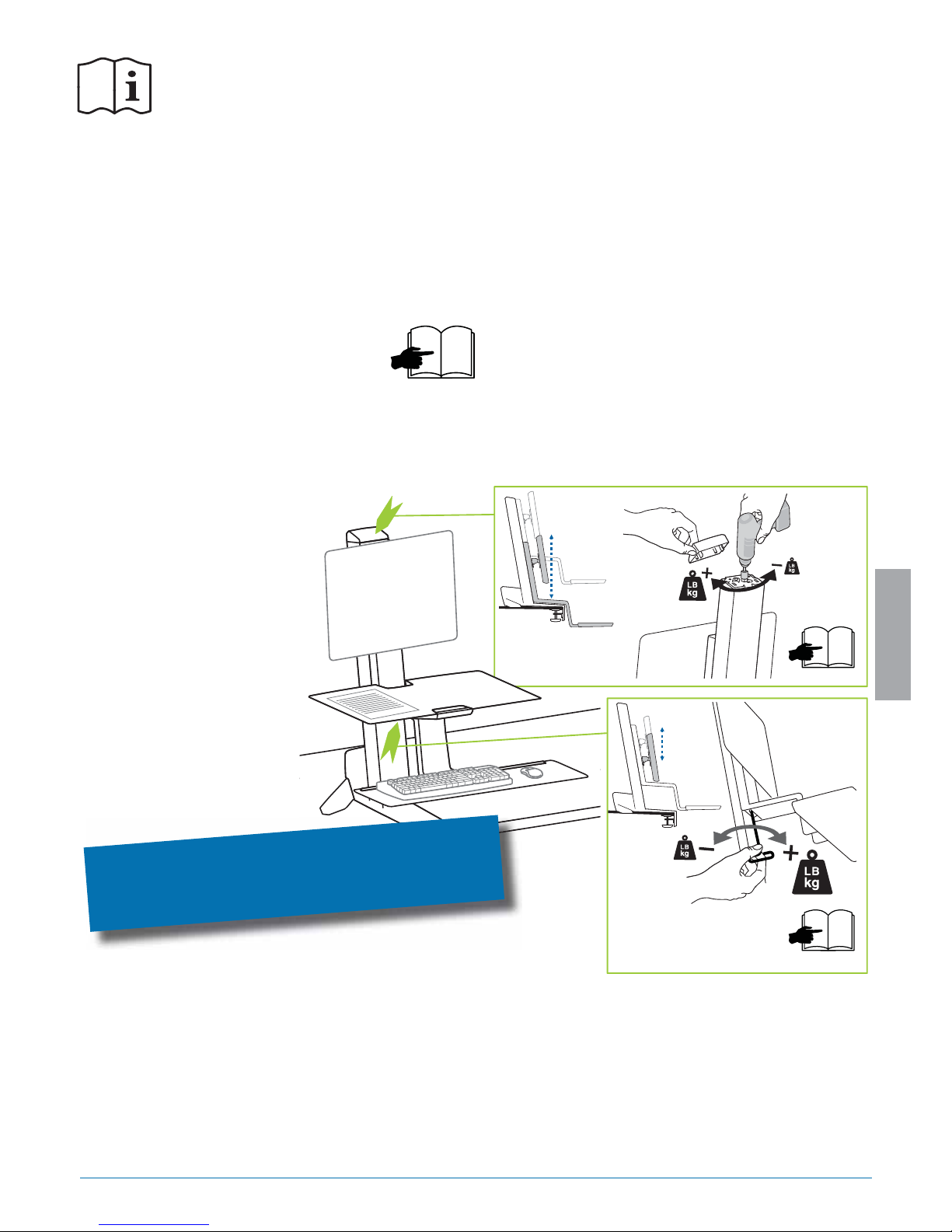
GREEN ARROWS MARK IMPORTANT ADJUSTMENT POINTS
After installation, adjust product to properly handle added weight.
To view a video on this adjustment procedure, go to
install.ergotron.com
Important! You will need to adjust this product after installation is complete. Make sure all your equipment
is properly installed on the product before attempting adjustments. This product should move smoothly
and easily through the full range of motion and stay where you set it. If movements are too easy or
diffi cult or if product does not stay in desired positions, follow the adjustment instructions to create
smooth and easy movements. Depending on your product and the adjustment, it may take many turns to
notice a difference. Any time equipment is added or removed from this product, resulting in a change in
the weight of the mounted load, you should repeat these adjustment steps to ensure safe and optimum
operation.
Follow Steps 1 - 8 for Installation
888-33-332-W-02 rev.G • 11/15
4 of 12
AB
1
2
3
4
5
6
7
8
9
10
11
12
13
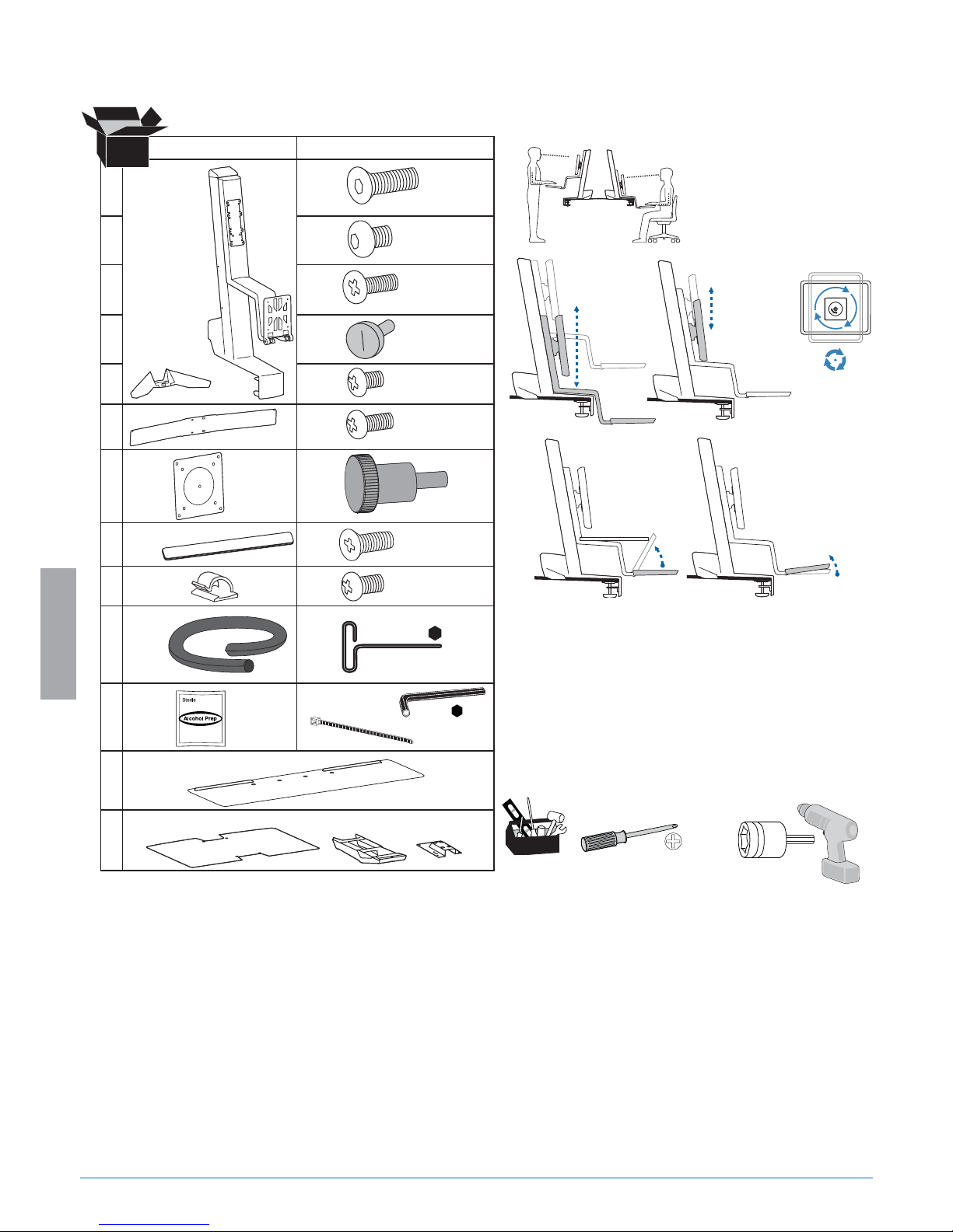
14mm
M4 x 10mm
M4 x 8mm
M4 x 10mm
8x
12x
4x
3x
2x
2x
M4 x 5mm
3x
M6 x 6mm
1x
1x
2x
1x
1x
3x
M5 x 14mm
7.5˚
18"
(45.7 cm)
1x
2x
1x
4mm
3mm
2x
1x
1x
4x
1x
1x
M4x12mm
2x
M5 x 12mm
1x
4.8"
(122 mm)
68˚
ENGLISH
Components
Tools Needed
Features & Specifi cations
 Loading...