

Page 1
™
WorkFit
B, HD
User's Guide
For the latest User Installation Guide please visit: www.ergotron.com
English, Español, Français, Deutsch, Nederlands, Italiano, Svenska, 日本語, 汉语
www.ergotron.com |
888-24-227-G-01 rev. E • 12/19
USA: 1-800-888-8458
|
Europe: +31 (0)33-45 45 600
|
China: 400-120-3051
|
English
Japan: japansupport@ergotron.com
1 of 19
Page 2
Hazard Symbols Review
These symbols alert users of a safety condition that
demands attention. All users should be able to
recognize and understand the signi cance of the following Safety Hazards if encountered on the product
or within the documentation. Children who are not
e to recognize and respond appropriately to Safety
abl
Alerts should not use this product without adult
supervision!
Safety
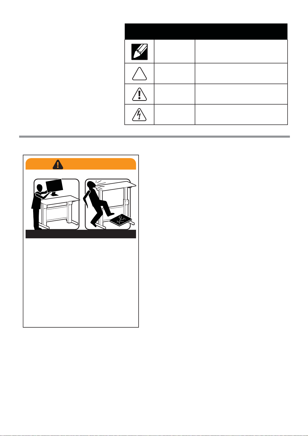
WARNING
IMPACT HAZARD
Symbol Signal Word Level of Hazard
NOTE
CAUTION
WARNING
ELECTRICAL
A NOTE indicates important information that helps you
make better use of this product.
A CAUTION indicates either potential damage to
hardware or loss of data and tells you how to avoid the
problem.
A WARNING indicates either potential for property damage, personal injury, or death.
An Electrical indicates an impending electrical hazard
which, if not avoided, may result in personal injury, re
and/or death.
Moving Parts Can Crush And Cut
Minimize Lift Strength BEFORE:
- Removing Mounted Equipment
and
Insert 4 Stop Screws BEFORE:
- Shipping or Storing (i.e. when Desk is not upright).
To Minimize Lift Strength
Refer to installation manual for instructions on
how to minimize lift strength.
To Insert 4 Stop Screws
Refer to installation manual for instructions on
Failure to heed this warning may result in
serious personal injury or property damage!
For More information and instructions visit www.ergotron.com
or contact Ergotron Customer Care at 1-800-888-8458.
Refer to Appendix A at the end of this manual
Refer to Appendix B at the end of this manual
installing stop screws.
826-901-00
2 of 19
888-24-227-G-01 rev. E • 12/19
Page 3
Safety
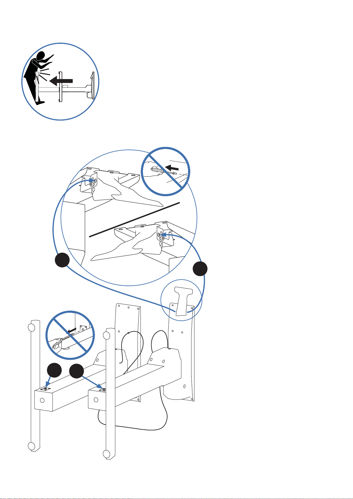
WARNING! Stop screws are pre-installed in this product to secure it in the compressed position
during shipping and installation. DO NOT REMOVE THESE SCREWS UNTIL INSTRUCTED TO DO SO
IN THESE INSTRUCTIONS. Make sure these screws are in place before starting installation. Failure
to follow these instructions may cause lift engine to expand rapidly and may result in equipment
damage and or personal injury. If any of the 4 stop screws are not installed in these locations,
contact customer care before continuing with installation.
DO NOT REMOVE SCREWS!
IMPORTANT!
Save these stop screws and instructions. Install stop screws
when shipping or storing this product. Failure to follow
these instructions may cause lift engine to expand rapidly
and may result in equipment damage and or personal
injury.
3
DO NOT REMOVE SCREWS!
1
2
4
888-24-227-G-01 rev. E • 12/19
3 of 19
Page 4
Safety
Important! You will need to adjust this product after installation is complete. Make sure all your equipment is properly
installed on the product before attempting adjustments. This product should move smoothly and easily through
the full range of motion and stay where you set it. If movements are too easy or di cult or if product does not stay
in desired positions, follow the adjustment instructions to create smooth and easy movements. Depending on your
product and the adjustment, it may take many turns to notice a di erence. Any time equipment is added or removed
from this product, resulting in a change in the weight of the mounted load, you should repeat these adjustment steps
to ensure safe and optimum operation.
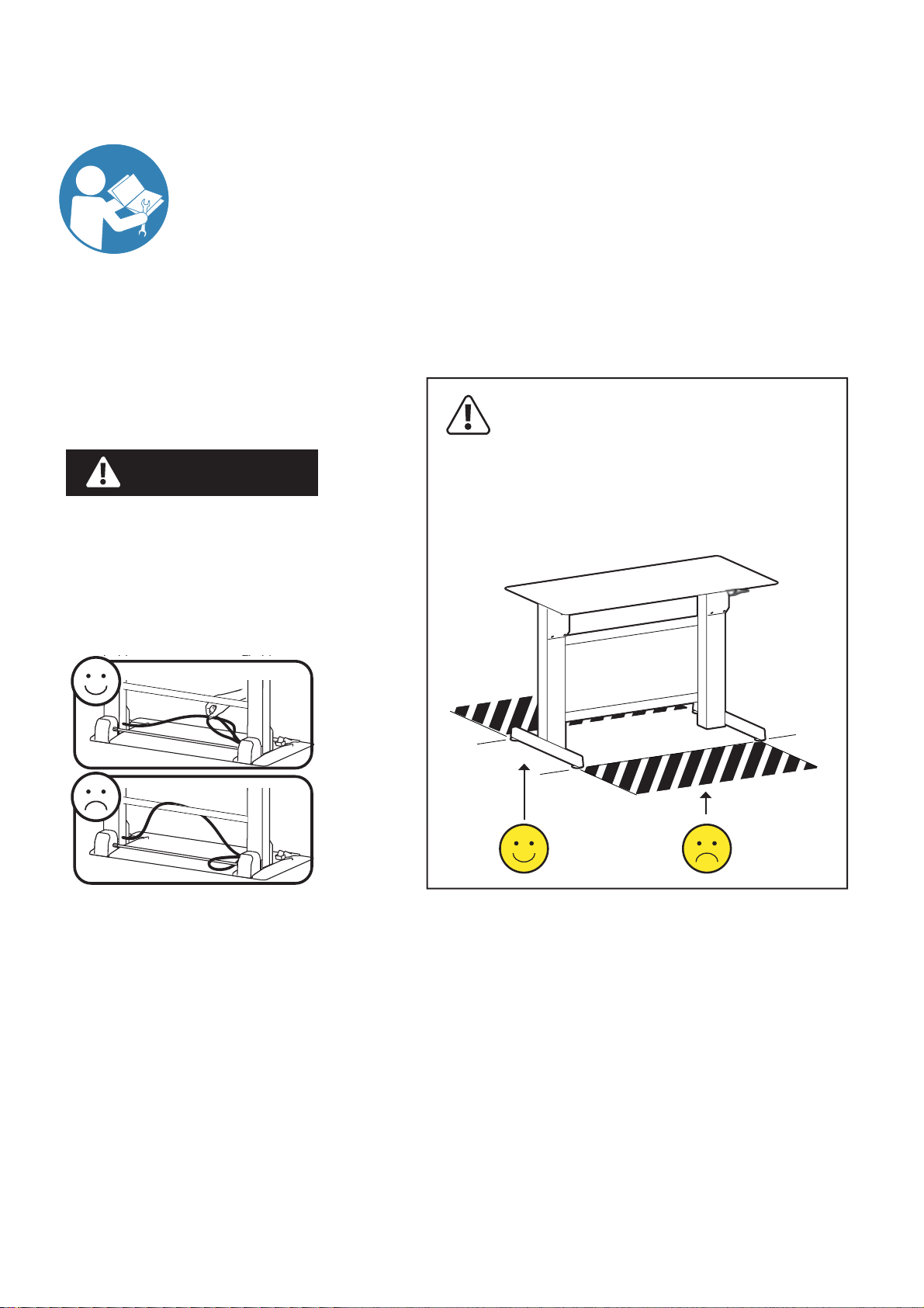
WARNING
Keep Brake Cables Away from
Sync Rod and Crossbars
During Installation!
Failure to keep the brake cables away from
sync rod and crossbars may restrict lift
motion and may cause equipment damage
or personal injury! Refer to instruction
manual for more information.
WARNING! TIPPING HAZARD!
When mounting accessories to the
WorkFit-D, they must stay within the foot
print. Do not mount accessories past the
front and rear worksurface! Failure to follow this warning may result in equipment
damage and or personal
injury.
4 of 19
888-24-227-G-01 rev. E • 12/19
Page 5

Features & Specifi cations
0.80”-1.75”*
(20-44 mm)
23.5”-30.5”*
(597-775 mm)
22.5-88 lbs (10.2-40 kg)*
41"-72" *
(1041-1829 mm)
Important! You will need to adjust this product after installation is
complete. Make sure all your equipment is properly installed on the
product before attempting adjustments. This product should move
smoothly and easily through the full range of motion and stay where
you set it. If movements are too easy or di cult or if product does
not stay in desired positions, follow the adjustment instructions to
create smooth and easy movements. Depending on your product
and the adjustment, it may take many turns to notice a di erence.
Any time equipment is added or removed from this product,
resulting in a change in the weight of the mounted load, you
should repeat these adjustment steps to ensure safe and optimum
operation.
Wood Worksurface Weight Estimator
Worksurface
Thickness
Estimated Weight
per square foot
0.80” (20 mm) 2.9 lbs (1.32 kg)
1.25” (32 mm) 4.5 lbs (2.04 kg)
1.75” (44 mm) 6.3 lbs (2.86 kg)
*Total weight of worksurface and mounted equipment must
be < 88 lbs (40 kg).
Worksurface must meet ALL dimensional and weight range
speci cation requirements.
WARNING! The addition of accessories can negatively impact the
tip performance.
888-24-227-G-01 rev. E • 12/19
5 of 19
Page 6
1/4”
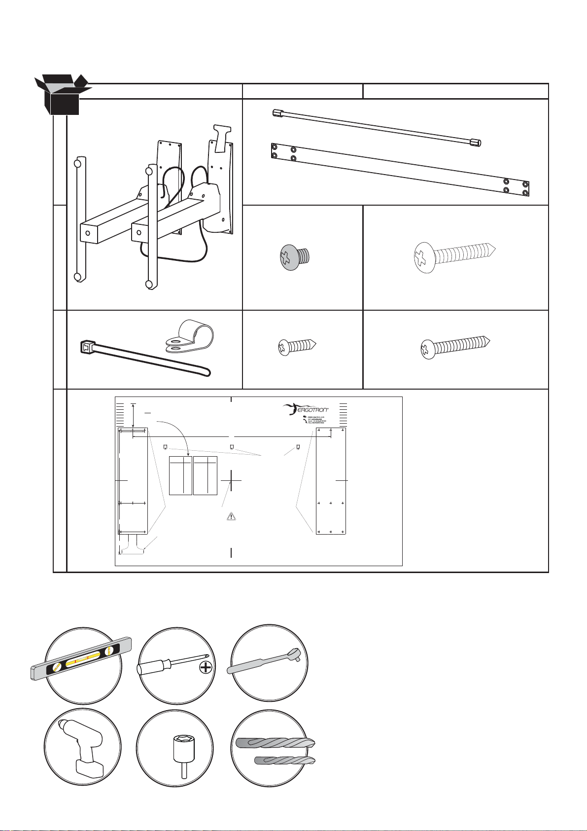
Components
AB C
1x
1x
1x
1
2x
2
16x
M5 x 6mm
17x
#12-14 x 5/8”
3x
3
3x
M2.9 x 8mm
4x
ST3.9 x 16mm
2x
1x
4.25” (108 mm)
3.75” (95 mm)
3.25” (83 mm)
2.75” (70 mm)
2.25” (57 mm)
1.75” (44 mm)
1.25” (32 mm)
0.75” (19 mm)
0.25” (6 mm)
Align
REAR
Edge of Worksurface X distance
from the back of the Base Brackets.
X
See table for value of
your worksurface.
Back of Base Bracket
2.1262.126
WORKSURFACE TEMPLATE FOR WORKFIT-B, HD
X
based on the depth of
Lay this template on the bottom of your worksurface
to drill the holes to attach the WorkFit-D, Base.
35.197
4.25” (108 mm)
3.75” (95 mm)
3.25” (83 mm)
2.75” (70 mm)
2.25” (57 mm)
1.75” (44 mm)
1.25” (32 mm)
0.75” (19 mm)
0.25” (6 mm)
12.992
4
5.118
3.900
Tools Needed
Depth of
Worksurface
23.50 - 24.25”----0.25”
24.25 - 25.00”----0.75”
25.00 - 25.75”----1.25”
25.75 - 26.50”----1.75”
26.50 - 27.25”----2.25”
27.25 - 28.00”----2.75”
28.00 - 28.75”----3.25”
28.75 - 29.50”----3.75”
29.50 - 30.25”----4.25”
Use Drill Bit #21,
Ø 0.19” (4.8 mm)
to drill these 8 holes
0.375” (9.5 mm) deep.
Brake Release
DIMENSIONS ARE IN INCHES
14mm
Depth of
X
X
Worksurface
597 - 616 mm---6 mm
616 - 635 mm---19 mm
635 - 654 mm---32 mm
654 - 673 mm---44 mm
673 - 692 mm---57 mm
692 - 711 mm---70 mm
711 - 730 mm---83 mm
730 - 749 mm---95 mm
749 - 768 mm---108 mm
Center Point of Base Brackets
TIPPING HAZARD!
Center Worksurface from Side-to-Side Across Base Brackets.
Failure to follow these instructions may make this product unstable
and may result in equipment damage and/or personal injury.
Use Drill Bit #46,
Ø 0.081” (2mm)
to drill these 3 holes
0.24” (6 mm) deep.
Use Drill Bit #21,
Ø 0.19” (4.8 mm)
to drill these 9 holes
0.375” (9.5 mm) deep.
823-558-00 rev.A 05/13
6 of 19
#12, Ø 0.19” (4.8mm)
#46, Ø 0.081” (2mm)
888-24-227-G-01 rev. E • 12/19
Page 7

Set-up Steps
Place the worksurface on a clean oor with the top side facing down.
1
Center Template
Side-to-Side on
worksurface.
Align REAR Edge of Worksurface X distance from the back of the Base Brackets.
See table for value of X based on the
Use Drill Bit #46,
0.081” (2mm)
Ø
to drill these 3 holes
0.24” (6 mm) deep.
Use Drill Bit #21,
0.19” (4.8 mm)
Ø
to drill these 8 holes
3/8” (9.5 mm) deep.
Center Point of Base Brackets
TIPPING HAZARD!
Center Worksurface from Side-to-Side Across Base Brackets.
Failure to follow these instructions may
and may result in equipment damage and/or personal injury.
Brake Release
depth of your worksurface.
Use Drill Bit #21,
0.19” (4.8 mm)
Ø
to drill these 9 holes
3/8” (9.5 mm) deep.
make this product unsta
ble
Depth of
Your Worksurface
4.25” (108 mm)
3.75” (95 mm)
3.25” (83 mm)
2.75” (70 mm)
2.25” (57 mm)
1.75” (44 mm)
1.25” (32 mm)
0.75” (19 mm)
0.25” (6 mm)
Align
REAR
Edge of Worksurface X distance
from the back of the Base Brackets.
X
See table for value of
your worksurface.
Back of Base Bracket
2.1262.126
Tape Template in place.
X
based on the depth of
Use Drill Bit #46,
0.081” (2mm)
Ø
to drill these 3 holes
0.24” (6 mm) deep.
Use Drill Bit #21,
0.19” (4.8 mm)
Ø
to drill these 8 holes
3/8” (9.5 mm) deep.
Brake Release
Depth of
Worksurface
X
23.50 - 24.25”----0.25”
24.25 - 25.00”----0.75”
25.00 - 25.75”----1.25”
25.75 - 26.50”----1.75”
26.50 - 27.25”----2.25”
27.25 - 28.00”----2.75”
28.00 - 28.75”----3.25”
28.75 - 29.50”----3.75”
29.50 - 30.25”----4.25”
Use Drill Bit #21,
0.19” (4.8 mm)
Ø
to drill these 9 holes
Center Point of Base Brackets
TIPPING HAZARD!
Center Worksurface from Side-to-Side Across Base Brackets.
Failure to follow these instructions may make this product u
and may result in equipment damage and/or personal injury.
3/8” (9.5 mm) deep.
Depth of
Worksurface
597 - 616 mm ---6 mm
616 - 635 mm ---19 mm
635 - 654 mm ---32 mm
654 - 673 mm ---44 mm
673 - 692 mm ---57 mm
692 - 711 mm ---70 mm
711 - 730 mm ---83 mm
730 - 749 mm ---95 mm
749 - 768 mm ---108 mm
nstable
X
888-24-227-G-01 rev. E • 12/19
Use Drill Bit #46,
0.081” (2mm)
Ø
to drill these 3 holes
0.24” (6 mm) deep.
Use Drill Bit #21,
0.19” (4.8 mm)
Ø
to drill these 8 holes
3/8” (9.5 mm) deep.
Center Point of Base Brackets
TIPPING HAZARD!
Center Worksurface from Side-to-Side Across Base Brackets.
Failure to follow these instructions may make this product u
and may result in equipment damage and/or personal injury.
Brake Release
Use Drill Bit #21,
0.19” (4.8 mm)
Ø
to drill these 9 holes
3/8” (9.5 mm) deep.
nstable
7 of 19
Page 8

Set-up Steps
Using the speci ed drill bit, drill the 17 holes for base.
#12, Ø 0.19” (4.8mm)
Drill holes 0.375" (9.5 mm) deep.
TIP: To ensure proper depth, place a
piece of tape on the drill bit 0.375” (9.5
mm) from the tip.
Use Drill Bit #46,
Ø 0.081” (2mm)
to drill these 3 holes
0.24” (6 mm) deep.
Use Drill Bit #21,
0.375"
(9.5 mm)
Ø 0.19” (4.8 mm)
to drill these 8 holes
3/8” (9.5 mm) deep.
Center Point of Base Brackets
TIPPING HAZARD!
Center Worksurface from Side-to-Side Across Base Brackets.
Failure to follow these instructions may make this product u
and may result in equipment damage and/or personal inju
Brake Release
Use Drill Bit #21,
Ø 0.19” (4.8 mm)
to drill these 9 holes
3/8” (9.5 mm) deep.
nstable
ry.
Using the speci ed drill bit, drill the 3 holes for cable clips.
#46, Ø 0.081” (2mm)
Drill holes 0.24" (6 mm) deep.
TIP: To ensure proper depth, place a piece of tape on the drill bit
0.24" (6 mm) from the tip.
Use Drill Bit #46,
Ø 0.081” (2mm)
to drill these 3 holes
0.24” (6 mm) deep.
Use Drill Bit #21,
Ø 0.19” (4.8 mm)
to drill these 8 holes
3/8” (9.5 mm) deep.
0.24"
(6 mm)
Center Point of Base Brackets
TIPPING HAZARD!
Center Worksurface from Side-to-Side Across Bas
Failure to follow these instructions may make this product unstable
and may result in equipment damage and/or personal injury.
Brake Release
Use Drill Bit #21,
Ø 0.19” (4.8 mm)
to drill these 9 holes
3/8” (9.5 mm) deep.
e Brackets.
Remove Template.
8 of 19
WORKSURFACE TEMPLATE FOR WORKFIT-D, BASE O
DIMENSIONS ARE IN INCHES
NLY
888-24-227-G-01 rev. E • 12/19
Page 9

Set-up Steps
Place the worksurface on a clean oor with
2
3
the top side facing down.
Carefully position the leg with the hand
brake on the right end of the worksurface.
Place the other leg on the left end.
NOTE: The brake cable is attached to both legs. Take care when removing the legs from the packaging to avoid damaging or pulling the
brake cable from the legs.
Set the right leg (with hand brake) upright on the
worksurface.
Partially insert 3 of the provided #12-14 wood
screws at the rear of the leg, 3 near the middle of
the leg and 2 at the front of the leg.
Front Edge of Worksurface
Rear Edge of Worksurface
8x
4
#12-14 x 5/8”
NOTE: Do not fully
insert the screws
into the worksurface
at this time. Leave
approximately 1/8”
space.
Attach one end of the sync rod to the
right leg as illustrated. Make sure the
brake cables don’t loop around the sync
rod. See Warning, right.
Front =2 screws
Middle = 3 screws
Rear = 3 screws
WARNING
Keep Brake Cables Away from
Sync Rod and Crossbars
During Installation!
Failure to keep the brake cables away from
sync rod and crossbars may restrict lift
motion and may cause equipment damage
or personal injury! Refer to instruction
manual for more information.
888-24-227-G-01 rev. E • 12/19
9 of 19
Page 10

Set-up Steps
Set the left leg (without
5
hand brake) upright on the
worksurface.
Attach the left end of the
sync rod to the left leg.
Make sure the brake
don’t loop around the sync
rod. See Warning, right.
cables
WARNING
Keep Brake Cables Away from
Sync Rod and Crossbars
During Installation!
Failure to keep the brake cables away from
sync rod and crossbars may restrict lift
motion and may cause equipment damage
or personal injury! Refer to instruction
manual for more information.
6
7
Partially insert 9 of the provided #12-14 wood screws
in the left leg and worksurface.
Front =2 screws
Middle = 3 screws
Rear = 3 screws
Use a Phillips screwdriver to insert the provided M5x6
mm screws into the two crossbars connecting the left
and right legs. Make sure the brake cables don’t
loop around the crossbars.
9x
#12-14 x 5/8”
NOTE: Do not
fully insert
the screws
into the worksurface at this
time. Leave
approximate-
ly 1/8” space.
16x
M5 x 6mm
8
Tighten the screws slightly one at a time
and repeat to ensure that
on every screw is equal.
NOTE: Do not overtighten screws.
overtightening screws may result in stripping
the holes and may cause the installation to be
unsafe.
Use a Phillips screwdriver to tighten
down the screws attaching the legs to
the worksurface.
NOTE: Do not overtighten screws. overtightening
screws may result in stripping the holes and may
cause the installation to be unsafe.
the tension
10 of 19
888-24-227-G-01 rev. E • 12/19
Page 11

Set-up Steps
If your brake release handle is not aligned with the front edge of your worksurface and you
9
would like it to be, follow these instructions to relocate the brake release handle.
a
Relocate brake release handle along front edge
b
the leg only. DO NOT attach brake release handle in front of or to the outside of the leg.
Make sure cable has enough slack to allow worksurface to fully extend up and down.
c d
#46, Ø 0.081” (2mm)
of worksurface and next to the inside of
4x
ST3.9 x 16mm
888-24-227-G-01 rev. E • 12/19
11 of 19
Page 12

Set-up Steps
10
Capture the brake cable in the cable clip as
illustrated, then use a Phillips screwdriver
to attach the cable clips to bottom of work
surface with the provided M2.9 x 8 mm screws.
3x
3x
M2.9 x 8mm
11
Using the 2 provided cable ties, attach brake cable
to the l
between the cable tie and the leg to allow desk top to
raise up unrestricted.
egs leaving as much slack in cable as possible
NOTE: Leave as much
slack in cable as possible
between the cable tie and
the leg to allow desk top
to raise up unrestricted.
Failure to follow this
may result in equipment
damage.
2x
12 of 19
888-24-227-G-01 rev. E • 12/19
Page 13

Set-up Steps
Set the desk upright onto its legs.
12
CAUTION!
LIFT HAZARD!
Two persons are required for
this step. Failure to follow
this warning may result in
equipment damage and or
personal injury.
13
Adjust the riser on each leg and check with a level to
make sure the work surface is even.
Spin Right to Lower.Spin Left to R aise.
888-24-227-G-01 rev. E • 12/19
13 of 19
Page 14

Set-up Steps
Remove the 4 brake stop screws before installing equipment.
14
Remove the 2 stop screws from the legs then the 2 stop screws from
the brake to allow the worksurface to raise and lower.
IMPORTANT!
Save these stop screws and instructions. Install stop
screws when shipping or storing this product. Failure
to follow these instructions may cause lift engine to
expand rapidly and may result in equipment damage
and or personal injury.
1
2
14 of 19
After you remove the 4 brake stop
screws, release the hand brake
(on the
worksurface up to highest level.
right leg) and move the
888-24-227-G-01 rev. E • 12/19
Page 15

Set-up Steps
Install all equipment.
15
CAUTION! Make sure you leave 20” (508mm)
of slack in all equipment cables to allow the
worksurface to raise up it’s full 20” (508mm).
Failure to allow enough slack in equipment
cables may cause cables to get pulled,
equipment to fall o desk and may result in
product damage and or personal injury.
16
Adjustment Step
Important! You will need to adjust this product after installation is complete. Make sure all your equipment is properly
installed on the product before attempting adjustments. This product should move smoothly and easily through
the full range of motion and stay where you set it. If movements are too easy or di cult or if product does not stay
in desired positions, follow the adjustment instructions to create smooth and easy movements. Depending on your
product and the adjustment, it may take many turns to notice a di erence. Any time equipment is added or removed
from this product, resulting in a change in the weight of the mounted load, you should repeat these adjustment steps
to ensure safe and optimum operation.
WARNING
IMPACT HAZARD
Moving Parts Can Crush And Cut
Minimize Lift Strength BEFORE:
- Removing Mounted Equipment
Insert 4 Stop Screws BEFORE:
- Shipping or Storing (i.e. when Desk is not upright).
To Minimize Lift Strength
Refer to installation manual for instructions on
To Insert 4 Stop Screws
Refer to installation manual for instructions on
Failure to heed this warning may result in
serious personal injury or property damage!
For More information and instructions visit www.ergotron.com
or contact Ergotron Customer Care at 1-800-888-8458
and
how to minimize lift strength.
installing stop screws.
.
826-901-00
888-24-227-G-01 rev. E • 12/19
15 of 19
Page 16

17
Release the hand brake (on the right leg) and move
the worksurface up to highest level.
Push in the cover located behind each leg to access
the adjustment point.
Maintain equal amount of tension on both legs by
alternating the adjustment from one leg to the
using a 14mm socket drill.
Adjustment Step
NOTE: The covers on the legs will not open
unless the worksurface has been lifted to it’s full
height. The worksurface will not lower unless
the covers have been completely closed.
other
14mm
=
Increase Lift Strength
If the mounted weight is too heavy or this
product does not stay up when raised, then you'll
need to increase Lift Strength:
Decrease Lift Strength
If the mounted weight is too light or this product
does not stay down when lowered, then you'll
need to decrease Lift Strength:
Make sure
covers are fully
closed before
lowering the
worksurface.
16 of 19
WARNING! DO NOT tip desk over to adjust. Only perform adjustment while desk is upright.
Failure to follow these instructions may cause the lift engine to expand rapidly and may result in
equipment damage and or personal injury.
888-24-227-G-01 rev. E • 12/19
Page 17

APPENDIX A - Minimize Lift Tension
WARNING. Before removing mounted equipment (monitor, arm, stand CPU, etc.), from desk, or
to prepare for shipping or storing the desk it is extremely important to minimize the lift tension.
Failure to install these instructions may cause lift engine to expand rapidly and may result in
equipment damage and or personal injury.
1. Release the hand brake (on the right leg) and move the worksurface up to
highest level.
2. Push in the cover located behind each leg to access the adjustment point.
NOTE: The covers on the legs will not open unless
the worksurface has been lifted to it’s full height. The
worksurface will not lower unless the covers have been
completely closed.
3. To minimize tension, turn adjustment bolts left using a 14mm
socket drill. Maintain equal tension on both legs by alternating
adjustment from one leg to the other. Keep adjusting until the
wrench stops turning.
4. Once at minimum tension it is ok to remove mounted equipment.
Turn adjustment
bolts left to
minimize tension.
=
14mm
Make sure
covers are fully
closed before
lowering the
worksurface.
888-24-227-G-01 rev. E • 12/19
WARNING! DO NOT tip desk over to adjust. Only perform adjustment while desk is
upright. Failure to follow these instructions may cause the lift engine to expand rapidly
and may result in equipment damage and or personal injury.
17 of 19
Page 18

APPENDIX B - Inserting Stop Screws
WARNING. Before shipping or storing the desk, or in cases where the desk is placed on it’s back
or side*, it is extremely important that the 4 stop screws be re-inserted. Failure to follow these
instructions may cause lift engine to expand rapidly and may result in equipment damage and
or personal injury.
1. Follow instructions in Appendix A to minimize lift tension.
2. Push the desk down to its lowest position.
3. Insert 2 stop screws at the bottom of each leg.
4. Insert the other 2 stop screws on each side of the hand brake located on the right
side of the worksurface.
5. Once the 4 stop screws have been
installed the desk can be shipped
or stored.
* Placing the desk on its back or side is not
recommended.
1
2
18 of 19
888-24-227-G-01 rev. E • 12/19
Page 19

Learn more about ergonomic computer use at: www.ergotron.com/ergonomics
For Warranty visit: www.ergotron.com/warranty
For Service visit: www.ergotron.com
For local customer care phone numbers visit: http://contact.ergotron.com
www.ergotron.com |
© 2016 Ergotron, Inc. All rights reserved. WorkFit™ is a registered trademark of Ergotron, Inc.
888-24-227-G-01 rev. E • 12/19
USA: 1-800-888-8458
|
Europe: +31 (0)33-45 45 600
|
China: 400-120-3051
|
Japan: japansupport@ergotron.com
19 of 19
 Loading...