

Ergotron StyleView SV44 User Manual
1/28
888-24-314-G-01 rev. D • 08/17
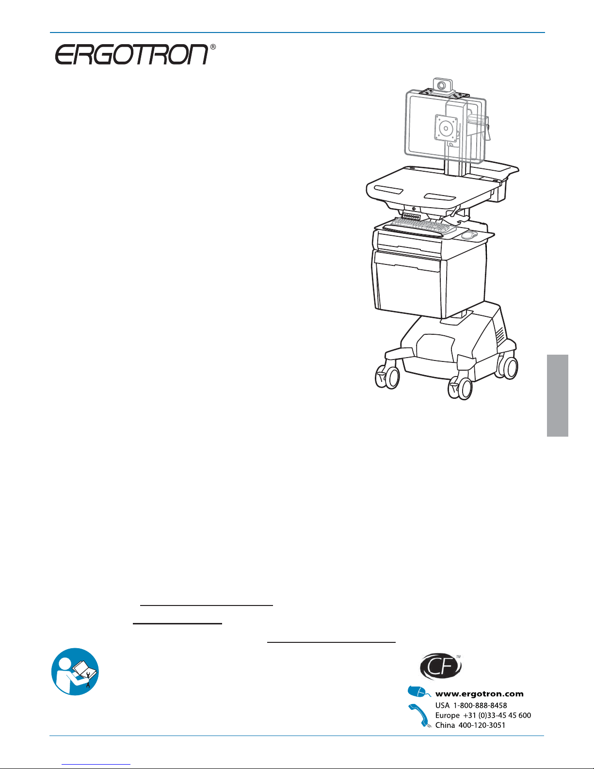
StyleView® SV44 Telepresence Cart
with Single LCD and Power System
User's Guide - English
Guía del usuario - Español
Manuel de l’utilisateur - Français
Gebruikersgids - Deutsch
Benutzerhandbuch - Nederlands
Guida per l’utente - Italiano
Användarhandbok - svenska
ユーザーガイド:日本語
用户指南 : 汉语
Includes
Constant Force™
Technology
ENGLISH
Components / Tools Needed ................................................................................... 2
Features & Speci cations ................................................................................................. 3 - 4
Dimensions .............................................................................................................................5
Set-up ................................................................................................................................ 6-20
Battery Charge/Discharge .....................................................................................................7
Adjustment .................................................................................................................... 17-18
Auto-Lock Drawer ........................................................................................................... 19-20
Change Fuse (1 Amp) and Reset Circuit Breakers ..............................................................21
Change Power System Batteries ...................................................................................22 - 23
Cart Storage (long term/short term) ...................................................................................24
Ergonomics ...........................................................................................................................25
Maintenance & Safety ...................................................................................................25 - 28
StyleView powered carts provide electrical AC power for mobile point
of care computing equipment in a healthcare environment. The carts
are not intended to power medical products or devices. Outlets are
provided to power information technology equipment only such as
computer equipment, computer peripherals, and teleconferencing
system equipment.
User Guide
For local customer care phone numbers visit: http://contact.ergotron.com
For Service visit: www.ergotron.com
For Warranty visit: www.ergotron.com/warranty
2/28
888-24-314-G-01 rev. D • 08/17
14mm (9/16")
4x
M4 x 10mm
10mm
1x
ABC D
1
2
3
4
5
6
7
AB C D
1
2
3
AB C
1
1x
2x
1x
1x
M4 x 8mm
3x
2x
4x
1x
4x
1x
1x
1x
1x
1x
12x
1x
2x
M4 x 12mm
1x
M4 x 8mm
1x
1x
1x
1x
1x
8x
1x
4mm
M4 x 10mm
1x
3mm
1x
4x 8x
1x
2x
M4 x 14mm
1x
M4 x 6mm
4x
M4 x 25mm
2x
Camera Shelf
CPU Holder
ENGLISH
IMPORTANT! This product will need tension adjustments once installation is complete. Make sure all equipment is properly installed on the product before attempting
range of motion or tension adjustments. Any time equipment is added or changed on this product resulting in a di erent mounted weight, you should repeat the
adjustment steps to ensure safe and optimum operation. This product should move smoothly and easily through the full range of motion and stay where you set it. If
movement is di cult or the product does not stay where you set it, follow the adjustment instructions to loosen or tighten the tension to create a smooth, easy motion.
Depending on your product and the adjustment, it may take many turns to notice a di erence.
Components
Tools Needed
3/28
888-24-314-G-01 rev. D • 08/17
4/11
3
2
2a
1
9
8
7
14
21
22
20
17
17
13
10
6
5
12
23
18
19
16
15
ENGLISH
Features & Speci cations
This Class A digital apparatus complies with Canadian
ICES-003.
Cet appareil numérique de la classe A est conforme à la
norme NMB-003 du Canada.
FCC Compliance Statement
The cart has been tested and found to comply with the
limits for a Class A digital device, pursuant to part 15
of the FCC Rules. These limits are designed to provide
reasonable protection against harmful interference
when the equipment is operated in a commercial
environment. This equipment generates, uses, and can
radiate radio frequency energy and, if not installed and
used in accordance with the instruction manual, may
cause harmful interference to radio communications.
Operation of this equipment in a residential area is likely
to cause harmful interference in which case the user
will be required to correct the interference at his own
expense.
Changes or modi cations not expressly approved
by Ergotron, Inc. could void the user’s authority to
operate the equipment.
Please contact Ergotron for complete EMC compatibility
information.
Worksurface 2a. Worksurface Lock and Release
User Interface for Power System
Secure Storage for Laptop, Thin Client or CPU
Front Handle
Height Adjustment Brake Handle
USB Hub connects keyboard and mouse USB cables
Keyboard tray slides out, tilts and allows for right or left mousing with attached mouse holder
Keyboard Light under Front Handle
Keyboard Light Switch
Cable Management and Storage for excess cables and power supplies
Storage Basket and Rear Handle
Locking Casters
Quick Reference Card
Power Cord Hooks
Scanner Holder
Antimicrobial worksurface and antimicrobial coating on wrist rest
Auto-Lock Drawer
Envelope Drawer - includes divider
Camera Shelf -
camera is supplied by customer.
CPU Holder for codec- Holds components 1.38" -3.75" (35-95 mm) thick
Medical Grade Power Strip: 120VAC/60 Hz; Output: 120VAC/60 Hz, 15 A maximum, total.
Ergotron's Medical Grade Power Strip includes 4 power outlets with individual protectors, power indicator light,
2 circuit breakers, a coiled cord with strain relief and storage hook, and a polarized connector designed for use
in Hospital Grade Receptacles.
• The Medical Grade Power Strip is certi ed to UL 1363A.
Power System
The StyleView AC Power System allows your power supply to travel with the cart. The Power System is
integrated in the base of the cart and comes standard with 2 batteries, power module, User Interface (UI), outlet
box and power cord.
• User Interface (UI): Allows power system output to be turned on or turned o , monitors battery charge
remaining, and provides low battery charge audible alarm.
• Two 33 Ah Sealed Lead Acid, Absorbed Glass Mat, 12VDC batteries.
• The minimum operational temperature is 10°C (50°F) and the maximum operational temperature is 29°C (86°F). The
recommended humidity range for operation is 5-95% rH.
• The recommended cart storage temperature is 15°C (59°F). At this temperature, the battery’s age-related
capacity loss is minimized. The minimum storage temperature is -20°C (-4°F) and the maximum storage
temperature is 50°C (122°F). The recommended humidity range for storage is 5-95% rH.
1.
2.
3.
4.
5.
6.
7.
8.
9.
10.
11.
12.
13.
14.
15.
16.
17.
18.
19.
20.
21.
22.
23.
Height Adjustable LCD Mount attaches LCDs or tablet PC's with 75x75 or
100x100mm mounting interface
BATTERY
LEAD
-20 °C
- 4 °F
50 °C
122 °F
Relative
Humidity
Range
5-95% rH
10 °C
50 °F
29 °C
86 °F
Relative
Humidity
Range
5-95% rH
Operational Storage
Part Number Power System
SV44-53E1-1
Input: 120VAC/60 Hz; 5.1A
Output: 120VAC/60 Hz, 400VA/300W.
• The cart and power system are certi ed to UL 60601 and CAN/CSA-C22.2 60601-1:08
WARNING
IMPACT HAZARD!
MOVING PARTS CAN CRUSH AND CUT.
Failure to heed this warning may result in serious personal
injury or property damage!
www.ergotron.com
Minimize Lift Tension BEFORE:
Removing Mounted Equipment, Shipping Cart, Storing Cart.
826-501
14mm (9/16”)
AVERTISSEMENT
DANGER D’IMPACT!
LES PARTIES EN MOUVEMENT PEUVENT ÉCRASER ET COUPER.
Il existe un risque de blessure corporelle ou d’endommagement
matériel en cas de non respect de cet avertissement.
Minimisez la tension d’élévation AVANT:
de retirer l’équipement xé, d’expédier le chariot, de stocker le chariot
CAUTION: Close worksurface before opening drawers. Open only one
drawer at a time. Do Not push cart when drawers or worksurface are open.
Failure to follow these instructions may cause the cart to be unstable.
4/28
888-24-314-G-01 rev. D • 08/17
20˚
5˚
24˚
12˚
<2 lbs (0.9 kg)
<2 lbs (0.9 kg)
<2 lbs (0.9 kg)
5"
(127 mm)
0 lbs (0 kg)
<5 lbs (2.3 kg)
<13 lbs (5.9 kg)
90˚90˚
< 2 lbs (1 kg)
<25 lbs (11.3 kg)
11.8"
(300 mm)
<5 lbs (2.3 kg)
ENGLISH
With Independent LCD Lift:
6-14 lbs (2.7-6.4 kg)
Without Independent LCD Lift:
20 lbs (9 kg)*
* See "How To Eliminate Independent LCD
Lift" section
Weight Capacity
*Combined LCD and CPU Compartment weight:
<27 lbs (12.2 kg).
Features & Speci cations
Open Worksurface
Closed Worksurface
CPU Compartment
Power "on"
Indicator Light
3' - 4' (91-122 cm) power cord*
Polarized
Connector
Outlet Protector
(individual flip-hatch for each outlet)
Circuit Breaker
Reset Button
*To obtain 6' (183 cm) of usable length, pre stretch cord to 7' (213 cm).
This may require up to 25 lbs (11.34 kg) of force.
CAUTION:
If the combined LCD and CPU weight is greater than 27 lbs (12.2 kg) then the CPU must be
mounted to the rear of the cart and codec (if present) can be placed into the CPU compartment.
CAUTION: DO NOT EXCEED
MAXIMUM LISTED WEIGHT
CAPACITY. SERIOUS INJURY OR
PROPERTY DAMAGE MAY OCCUR!
5/28
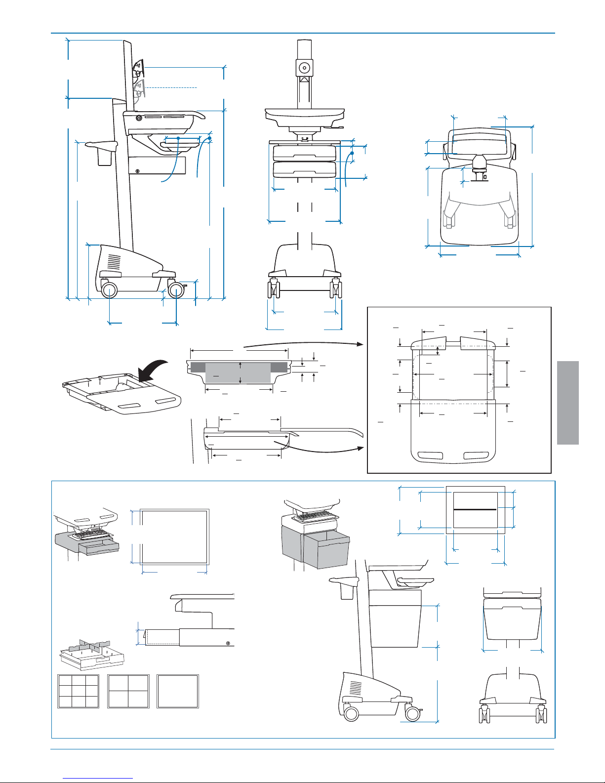
888-24-314-G-01 rev. D • 08/17
7" - 12"
(178-305 mm)
17"
(432 mm)
50.5"
(1283 mm)
2.9" (74 mm)
43"
(1092 mm)
3.4"
(86 mm)
1.75" (44 mm)
13"
(330 mm)
4"
(102 mm)
23" - 43"
(584-1092 mm)
31" - 51"
(787-1295 mm)
14.63"
(372 mm)
13.4"
(340 mm)
15.5"
(394 mm)
18.3"
(465 mm)
31"
(787 mm)
2.5"
(64mm)
19.75"
(502 mm)
22.38"
(568 mm)
< 14.75" (375 mm)**
< 2.75" (70 mm)
< 4" (102 mm)
*
< 12.25"
(311 mm)
< 12.25"
(311 mm)
*< 21.75"
(552 mm)
*< 17.63"
(448 mm)
*< 17.75"
(451 mm)
< 13"
(330 mm)
**< 2.75"
(70 mm)
< 2.3"
(58 mm)
**< 4.25"
(108 mm)
**< 7.75"
(197 mm)
**< 8"
(203 mm)
**< 2.75"
(70 mm)
**< 4"
(102 mm)
< 1.38"
(35 mm)
Side View
Top View
Front View
17.5"
(445 mm)
15.4"
(390 mm)
7.4"
(188 mm)
3.7"
(95 mm)
3.27"
(83 mm)
12.5"
(315 mm)
10.5"
(267 mm)
2.5"
(64 mm)
Front View
13"
(329 mm)
12"
(308 mm)
12.6"- 24.4”
(320-620 mm)
11"
(280 mm)
15.6"
(395 mm)
10.7"
(272 mm)
12.8"
(324 mm)
5.3"
(134 mm)
5.4"
(138 mm)
Side View
Top View
8.5"
(216 mm)
ENGLISH
Dimensions
When guring dimensions, include
mounted accessories, protruding cables
and port replicators or docking stations.
CPU Compartment
*Auto-Lock Drawer

6/28
888-24-314-G-01 rev. D • 08/17
1
b
c
3
a
2
abc
d
ENGLISH
Set-up
Release Brake to move riser.
CAUTION! Completely release brake
engagement before raising or lowering
the cart. Raising or lowering the cart with
the brake partially engaged may cause
product damage.
7/28
888-24-314-G-01 rev. D • 08/17
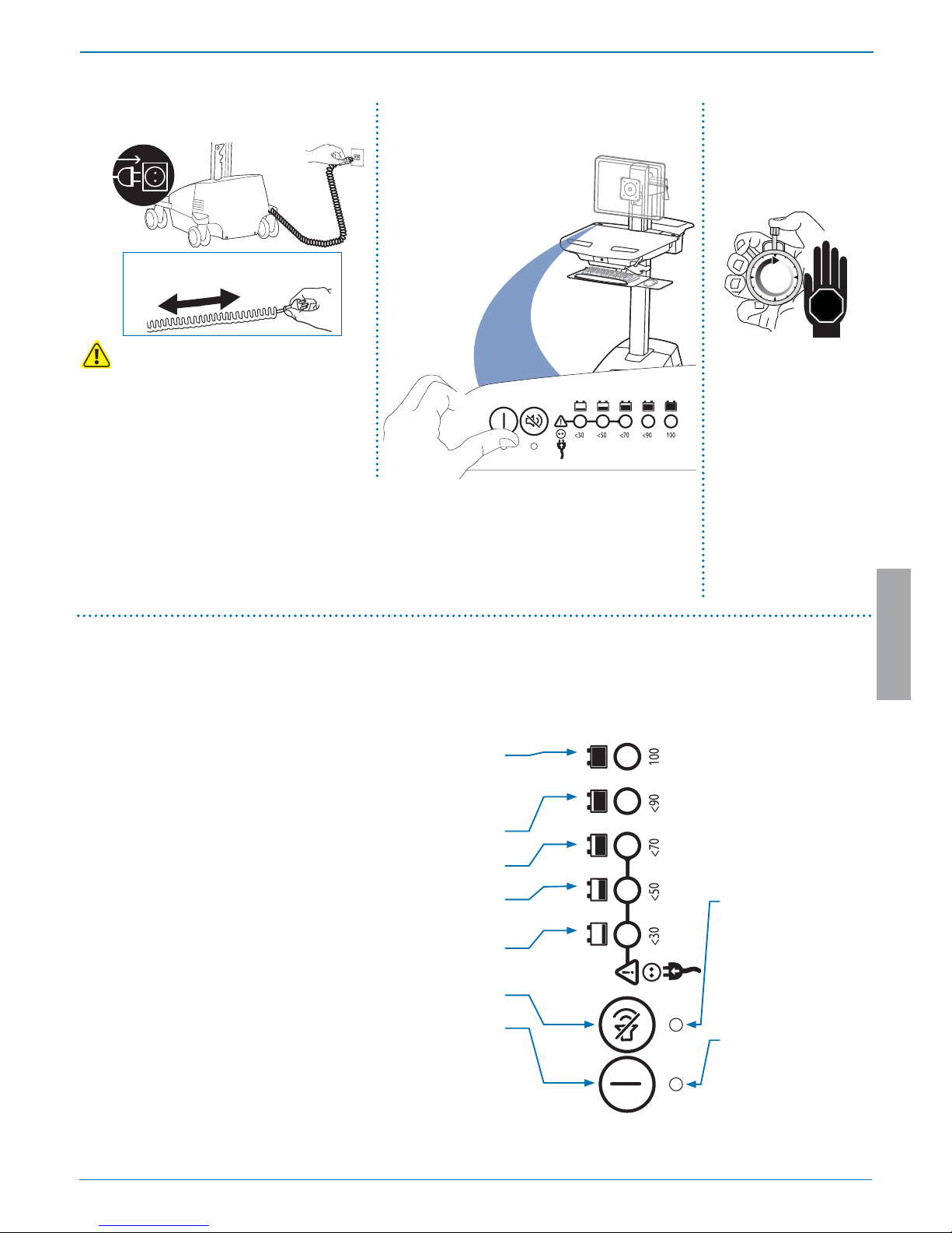
4
ab c
8hrs
7 hrs
07.00
ENGLISH
Set-up
Battery Charge/Discharge
Initial Power on/Charge Battery (takes approximately 7 hours to charge)
Turn on power system by holding power button down for
1 - 3 seconds.
With cart's power cord
plugged into the wall
outlet, wait until cart is
at 100% charge. (takes
aproximately up to 7 hours
to charge)
Plug Cart's Power Cord into wall outlet.
Do Not stretch coiled cord further than 8 feet
(2.5 meters), damage to the cord may occur.
Battery has 100% charge.
Light ashes when charging (power cord plugged into wall outlet)
Allow battery to continue
charging until light stops ashing. After light stops ashing, it is OK to unplug the
power cord from the wall.
You can use cart while charging.
Battery has less than 90% charge.
Battery has less than 70% charge.
Battery has less than 50% charge.
Battery has less than 30% charge. Light is red and alarm beeps. Plug-in power cord and charge
to 100%! You can use cart while charging.
Alarm Mute button. Pressing this will temporarily mute alarm.
Power button for internal power system outlets. Pressing this will provide or remove power to/
from components plugged into the internal outlets.
When lit, alarm is enabled and
will beep when battery charge
gets below 30%. For details on
enabling and disabling alarm
contact Ergotron Customer Care.
When lit, the power system is on.
When dark, power system is o .
This power system interface will alert you to the percentage of charge remaining in the cart battery with a series of steady or ashing red,
yellow or green lights, and an alarm that will beep when charge gets below 30%. Remember, the battery needs to be charged to 100%
every day, and you can use the cart while charging, so plug-in cord as often as possible to avoid running out of power!
NOTE: Put monitor in power save mode to optimize battery run time.
NOTE: Frequent operation of the cart while battery charge levels are
below 30% will signi cantly reduce the life of your battery and may
void your battery warranty.
CAUTION: There is no on/o switch on
this equipment; the AC power cord is the only
power disconnect. The socket outlet should be
easily accessible and should be installed near the
equipment.
8/28
888-24-314-G-01 rev. D • 08/17
5
a
b
c
1x
1x
1x
1x
1x
ENGLISH
Set-up
9/28
888-24-314-G-01 rev. D • 08/17
6
7
ab
c
a
cbd
4mm
ENGLISH
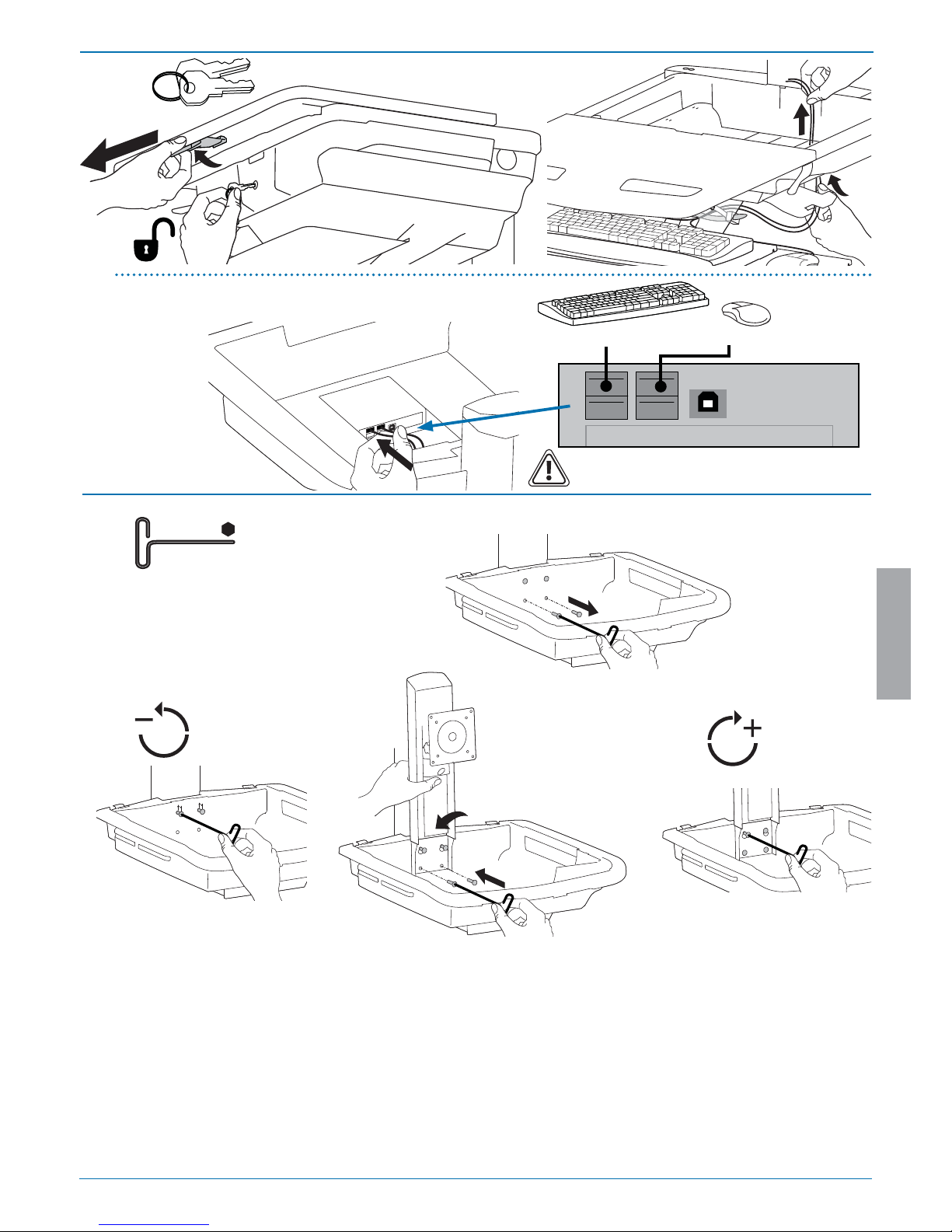
Set-up
Connect Keyboard and Mouse to USB Hub
NOTE: Bar Code Scanner should be connected directly to
computer USB port.
DO NOT connect Bar Code Scanner to the USB Hub.
USB (Type A)
USB (Type A)
 Loading...