

Page 1

888-61-101-G-00 rev.A • 05/14
1 of 9
User's Guide - English
Guía del usuario - Español
Manuel de l’utilisateur - Français
Gebruikersgids - Deutsch
Benutzerhandbuch - Nederlands
Guida per l’utente - Italiano
Användarhandbok - svenska
ユーザーガイド:日本語
用户指南 : 汉语
Neo-Flex Slide-out Keyboard Tray
Wall Mount
For the latest User Installation Guide please visit: www.ergotron.com
User's Guide
Page 2

888-61-101-G-00 rev.A • 05/14
2 of 9
1
Determine Ergonomic Mounting Height
Learn more about ergonomic computer use at:
www.computingcomfort.org
Height Position top of screen slightly below eye level.
Position keyboard at about elbow height with wrists at.
Distance Position screen an arm's length from face—at least 20” (508mm).
Position keyboard close enough to create a 90˚ angle in elbow.
Angle Tilt screen to eliminate glare.
Tilt the keyboard back 10° so that your wrists remain at.
To Reduce Fatigue
Breathe - Breathe deeply through your nose.
Blink - Blink often to avoid dry eyes.
Break • 2 to 3 minutes every 20 minutes
• 15 to 20 minutes every 2 hours.
Set Your Workstation to Work For YOU!
ABCD E
1
2
3
6
8-32 x 1/2"
1/8"
1/4-20 x 1/2"
set screw
3/32"
1x
1x
4x
1x
4x
4x
1x
1x
1x
2
1
1/2"
1/2"
4x
4x
4x
M6
2x
2x
1/4-20 x 2"
4x
4x
M6 x 70mm
ST6.3 x 50 mm
ST6.3 x 50 mm
See Wall Mounting Options for additional tools needed for your type of wall installation.
1x
Page 3

888-61-101-G-00 rev.A • 05/14
3 of 9
2
Wall Mounting Options
WARNING:
Ensure that the wall structure is capable of supporting four times the total
weight of mounted equipment. Mounting to wall surfaces that do not meet this
criteria may result in an unstable, unsafe condition which could lead to personal
injury and/or property damage. Consult a construction professional if you have
any doubt about what this means in regard to your particular application.
10mm
4x
4x
4x
M6
Requires minimum material thickness of 5/8” (16 mm).
4
4
5
6
Wood
Hollow Wall
Concrete
Studs ≥ 25 gauge steel
Ø 3/16" (5 mm)
Ø 3/16" (5 mm)
Ø 3/8" (10 mm)
2x
2x
4x
4x
Stud Finder
Stud Finder
M6 x 70mm
1/4-20 x 2"
ST6.3 x 50 mm
ST6.3 x 50 mm
Ø 1/2" (13 mm)
8“
(203mm)
1“
(25mm)
1“
(25mm)
2“
(51mm)
0.5“
(13mm)
≥ 5/8”
Sheetrock
Page 4

888-61-101-G-00 rev.A • 05/14
4 of 9
Wood
3
Attach to Wall
Studs ≥ 25 gauge steel
Wood
Studs ≥ 25 gauge steel
Stud Finder
Ø 3/16" (5 mm)
a
e
c b
d
4
2x
2x
7
ST6.3 x 50 mm
ST6.3 x 50 mm
NOTE: Fasteners may unwind due to vibration caused by movement of mounting solution over
time. Inspect mounting solution for loose fasteners on a routine basis. If desired, apply a light
duty thread locking adhesive to fasteners before installation to prevent back-out.
Page 5

888-61-101-G-00 rev.A • 05/14
5 of 9
4
7
Hollow Wall
3
Attach to Wall
ab
c
d
1. Push anchor plate into hole.
2. Pull loop back so plate opens at against inside surface of wall.
3. Push collar into hole.
4. Snap o loop.
1234
Ø 1/2" (13 mm)
4x
4x
1/4-20 x 2"
NOTE: Fasteners may unwind due to vibration caused by movement of mounting solution over
time. Inspect mounting solution for loose fasteners on a routine basis. If desired, apply a light
duty thread locking adhesive to fasteners before installation to prevent back-out.
≥ 5/8”
Sheetrock
Page 6

888-61-101-G-00 rev.A • 05/14
6 of 9
Concrete
3
Attach to Wall
3-1/8"
(80 mm)
c
d
NOTE: Fasteners may unwind due to vibration caused by movement of mounting solution over
time. Inspect mounting solution for loose fasteners on a routine basis. If desired, apply a light
duty thread locking adhesive to fasteners before installation to prevent back-out.
4
7
4x
123
10mm
4x
4x
M6
Ø 3/8" (10 mm)
M6 x 70mm
ab
WARNING:
Mounting holes must be at least 3-1/8” (80mm) deep and must be located within solid concrete, not mortar or covering material. If you drill into an area of concrete that is not solid,
reposition mounting holes until both anchors can be fully inserted into solid concrete!
WARNING:
Anchors that are not fully set in solid concrete will not
support the applied load resulting in an unstable, unsafe
condition which could lead to personal injury and/or prop-
erty damage. Consult a construction professional if you
have any doubt about what this means in regard to your
particular situation.
CAUTION: Make sure the wall
mount bracket is level, ush and
snug to the wall surface. DO NOT
OVERTIGHTEN THE BOLTS.
Page 7

888-61-101-G-00 rev.A • 05/14
7 of 9
4x
4
Attach Keyboard Tray
c
d
ba
2x
2x
4x
5
Attach Keyboard
8-32 x 1/2"
8-32 x 1/2"
1/8"
3/32"
3/32"
NOTE: Fasteners may unwind due to vibration caused
by movement of mounting solution over time. Inspect
mounting solution for loose fasteners on a routine basis.
If desired, apply a light duty thread locking adhesive to
fasteners before installation to prevent back-out.
e
f
cdba
1/4-20 x 1/2"
set screw
Page 8
888-61-101-G-00 rev.A • 05/14
8 of 9
c
b
a
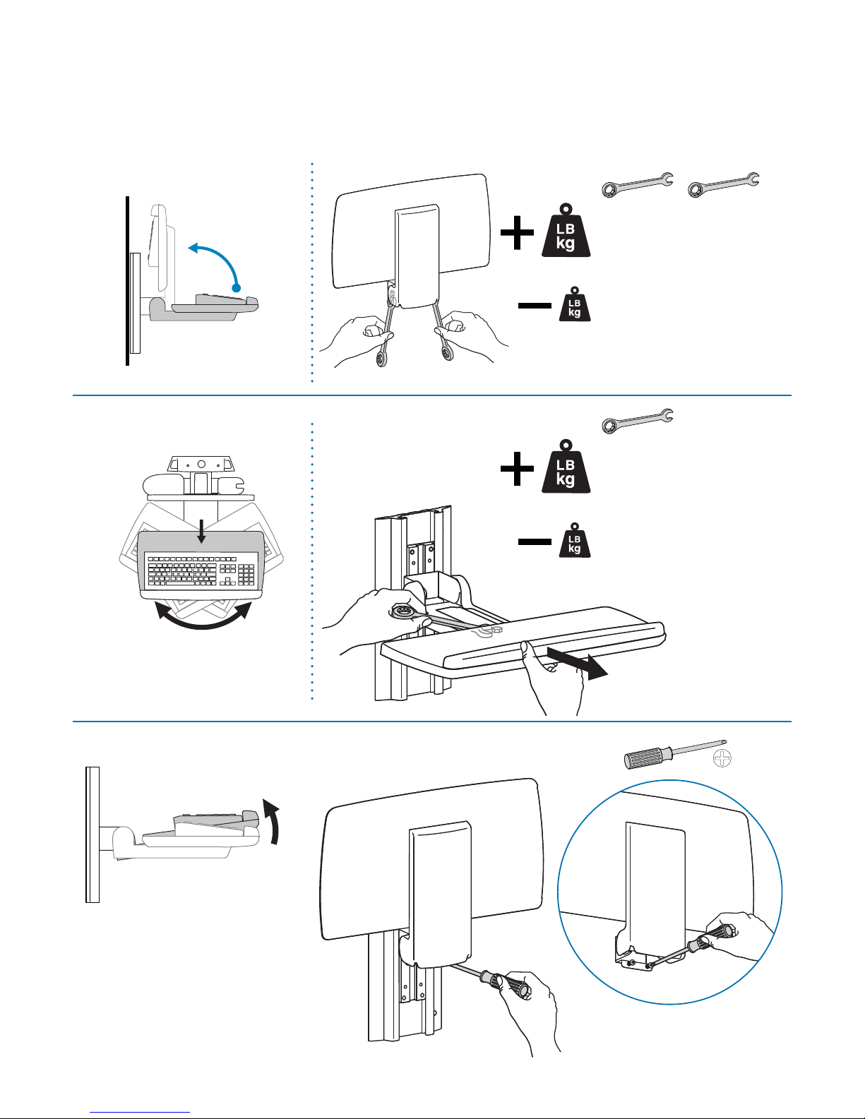
6
90˚
Range of Motion
This product is designed to adjust quickly and easily according to your needs – refer to following
steps for adjustment.
Tilt – Forward and Backward
Negative Tilt
Pan – Side-to-Side
1/2"
1/2"
1/2"
Increase Friction
If this product moves too easily from
side-to-side, then you'll need to
increase friction:
Decrease Friction
If this product is too di cult to move
from side-to-side, then you'll need to
decrease friction:
Increase Friction
If this product moves too easily from
side-to-side, then you'll need to
increase friction:
Decrease Friction
If this product is too di cult to move
from side-to-side, then you'll need to
decrease friction:
Page 9

888-61-101-G-00 rev.A • 05/14
9 of 9
8
Attach Cable Management
c da
7
Attach Mouse Pouch
For local customer care phone numbers visit: http://contact.ergotron.com
 Loading...