

Page 1
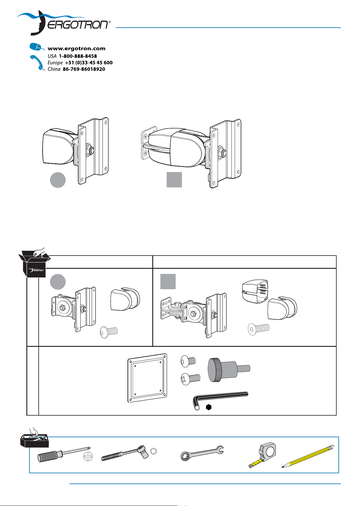
100 Series Flat Panel Monitor Pivots
a b
User's Guide
Vertical Surface, Direct Mount
1
2
AB
a b
4X
#8-32 x 5/16"
1x
75-100mm
4x
4x
M4 x 10mm
1x
4X
#8-32 x 3/8"
4x
#8-32
M4 x 10mm
3/32"
888-47-019-02 rev. P • 02/10
1/2"
1/2"
2
1
1 of 8
Page 2
1
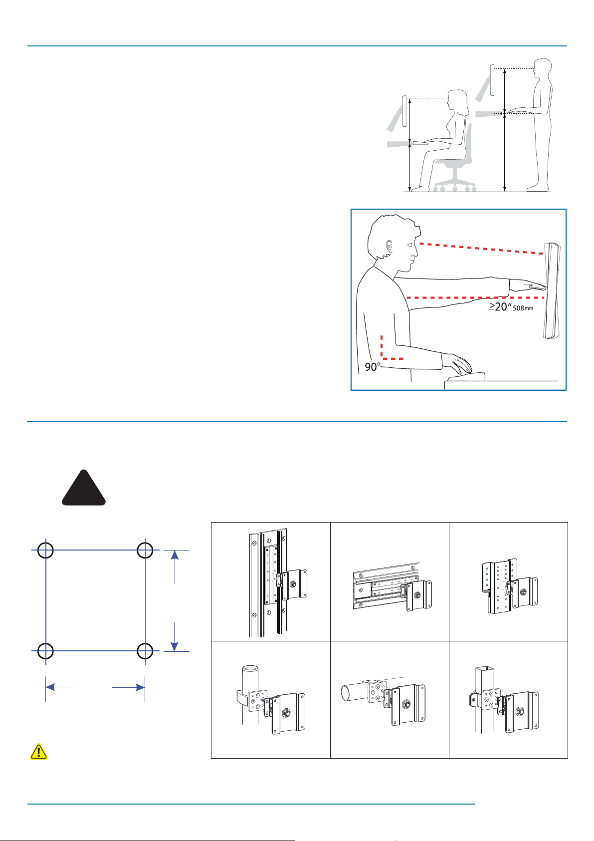
Determine Ergonomic Mounting Height
Set Your Workstation to Work For YOU!
Height Position top of screen slightly below eye level.
Position keyboard at about elbow height with wrists at.
Distance Position screen an arm's length from face—at least 20” (508mm).
Position keyboard close enough to create a 90˚ angle in elbow.
Angle Tilt screen to eliminate glare.
Tilt the keyboard back 10° so that your wrists remain at.
To Reduce Fatigue
Breathe - Breathe deeply through your nose.
Blink - Blink often to avoid dry eyes.
Break • 2 to 3 minutes every 20 minutes
• 15 to 20 minutes every 2 hours.
Learn more about ergonomic computer use at:
www.computingcomfort.org
2
Determine Mounting Confi guration
WARNING
Because surfaces vary widely and the ultimate mounting method is out of Ergotron’s control, it is
!
1.062"
(26.97mm)
imperative that you consult with appropriate engineering, architectural or construction professional
to ensure that your Ergotron mounting solution is mounted properly to handle applied loads.
1.062"
(26.97mm)
NOTE: Fasteners may unwind due to vibration caused by movement of mounting solution over time. Inspect mounting
solution for loose fasteners on a routine basis. If desired, apply a light duty thread locking adhesive to fasteners before
installation to prevent back-out.
888-47-019-02 rev. P • 02/10
2 of 8
Page 3
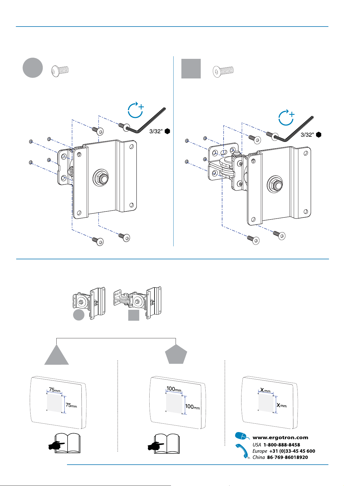
3
Mount Pivot
4X 4X
a
#8-32 x 5/16"
b
#8-32 x 3/8"
4
Attach Monitor
a
c
75 mm
4
+
b
d
100 mm
5
X mm
888-47-019-02 rev. P • 02/10
3 of 8
Page 4

!
If your monitor uses a screw size other than M4 x 10mm,
DO NOT use the M4 x 10mm screws or knob provided as
they could result in damage to the monitor.
c
75 mm
M4 x 10 mm M4 x 10 mm
4x
d
100 mm
4x
#8-32
3/32"
M4 x 10 mm M4 x 10 mm
4x
4 of 8
888-47-019-02 rev. P • 02/10
Page 5

Tilt Motion
5
Tilt monitor up and down through entire pivot range of motion. If it does not stay in place or
movement in one direction is stiff, pivot needs adjustment - see below. Adjust until monitor
stays in place and tilting forces, up or down, are equal.
Adjust Tilt
To Increase Tension: Turn screw clockwise.
To Decrease Tension: Turn screw counterclockwise.
1/2"
1/2"
Side-to-Side Motion
6
Move monitor side-to-side through entire range of motion. If it does not stay
in place at any point it will need adjustment - see below. Adjust so side-to-side
moving forces are equal.
Adjust Side-to-Side
To Increase Tension: Turn screw clockwise.
To Decrease Tension: Turn screw counterclockwise.
1/2"
1/2"
888-47-019-02 rev. P • 02/10
5 of 8
Page 6

7
Portrait/Landscape
Rotate monitor from Portrait to Landscape through entire range of motion. If
it does not stay in place or movement in one direction is stiff, tension needs
adjustment - see below. Adjust until monitor stays in place and tension,
portrait to landscape, is equal.
Adjust Portrait/Landscape
To Increase Tension: Turn screw clockwise.
To Decrease Tension: Turn screw counterclockwise.
8
1/2"
6 of 8
888-47-019-02 rev. P • 02/10
Page 7

Troubleshooting
?
Symptom Probable Cause Solution
Monitor tilts up and down too
easily or with diffi culty.
Monitor moves side-to-side too
easily or with diffi culty.
Monitor rotates from portrait
to landscape too easily or with
diffi culty.
* Weight Capacities:
5 - 25 lbs
(2 - 11.4 kgs)
Pivot Tension needs adjustment.
Monitor exceeds weight capacity*.
Pivot Tension needs adjustment.
Pivot Tension needs adustment.
5 - 23 lbs
(2 - 10.5 kgs)
Tilt Motion
8
Side-to-Side
9
Motion
Portrait/
10
Landscape
6
5
5
888-47-019-02 rev. P • 02/10
7 of 8
Page 8

8 of 8
888-47-019-02 rev. P • 02/10
 Loading...