

Page 1
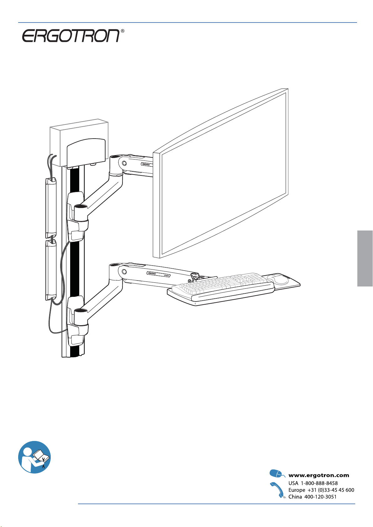
ASSEMBLY INSTRUCTIONS
LX Sit-Stand Wall Mount System
with Universal CPU Holder
ENGLISH
For the latest User Installation Guide please visit: www.ergotron.com
User's Guide - English
Guía del usuario - Español
Manuel de l’utilisateur - Français
Gebruikersgids - Deutsch
Benutzerhandbuch - Nederlands
Guida per l’utente - Italiano
Användarhandbok - svenska
ユーザーガイド:日本語
用户指南 : 汉语
888-45-277-W-03 rev.J • 02/17
1 of 28
Page 2
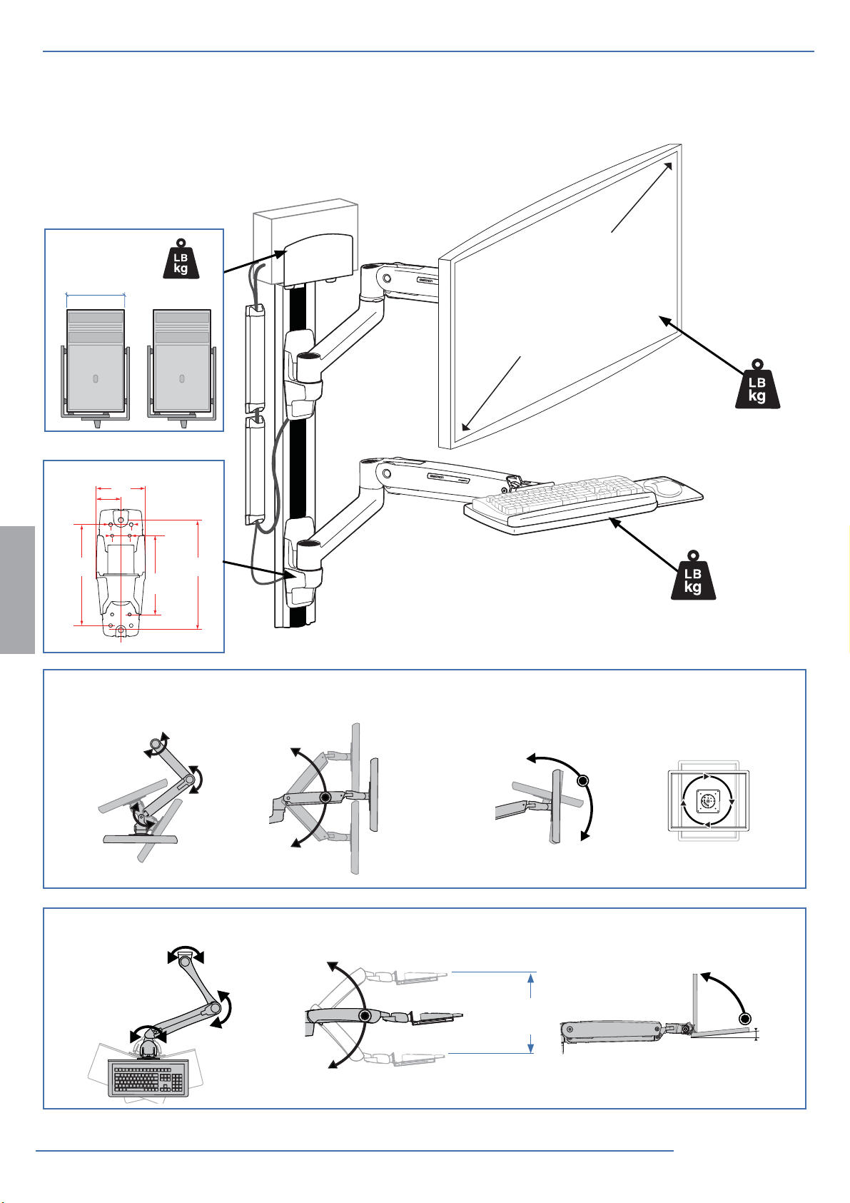
Features & Specifi cations
2" - 8"
(102 - 203 mm)
1.34"
(34mm)
6.5"
(165mm)
3.15"
(80mm)
1.57"
(40mm)
40 lbs (18 kg)
1.14"
(29mm)
7.1"
(180mm)
5.1"
(129mm)
Maximum Screen
Size* = 42”
*Limited to 25 lbs
maximum
25 lbs
(11.3 kg)
0-5 lbs
(0-2.3 kg)
ENGLISH
180°
180°
180°
180°
360°
360°
20"
(508 mm)
20"
(508 mm)
70°
5°
0° or 360°
90°
5°
2 of 28
888-45-277-W-03 rev.J • 02/17
Page 3
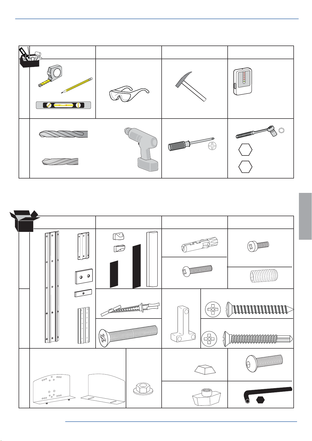
Tools Needed
ABCD
2
1
1
Concrete Wall Mounting
Ø 3/8” (10mm)
2
Wood Stud Mounting
Stud Finder
13 mm
Ø 3/16" (5mm)
Components
ABCD
1x
1x
1
1x
1x
2x
2x
2x
14x
1x
2x
4x
4x
1x
M4.2 x 25mm
7x
7/16"
ENGLISH
2x
M4 x 14mm
9x
1/4-20 x 1/2"
2
1x
3
888-45-277-W-03 rev.J • 02/17
2x
1x
14x
1/4-20 x 2"
2x
12x
2x
7x
2x
1x
M10 x 16mm
6mm
3 of 28
Page 4
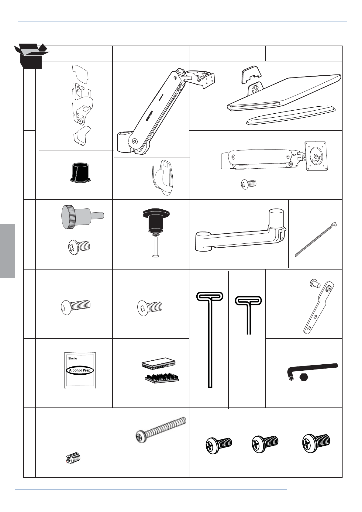
Components
ABCD
2x
1x
1
2x
1x
1x
1x
2x
1x
2
4x
1x
1x
4x
M4 x 10mm
3
4x
4x
2x
M6
M3 x 6mm
4x
ENGLISH
4
5
6
4x
M4 x 10mm
8x 4x
10-24 x 1/2"
5x
M8 M5 Kit
4x
4x
4x
M6 x 45mm
M4 x 8mm
M5x20mm
1x 1x
4x
M5 x 7mm
4x
4mm
1x
5mm
4x 4x 4x
1/8”
4 of 28
4x
M8-M5
Reducer
M4x12mm M5x12mm M6x12mm
888-45-277-W-03 rev.J • 02/17
Page 5
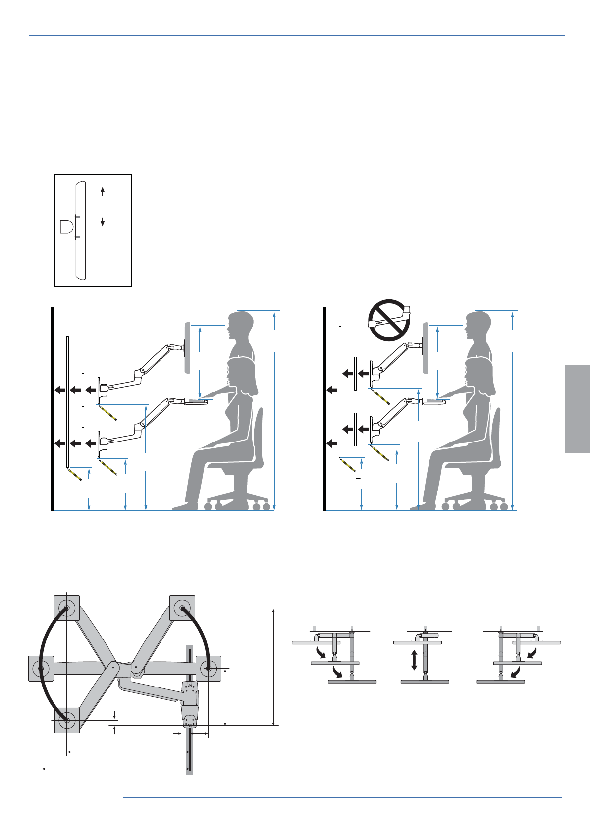
Mounting Height for Ergonomic Workstation
1
This mounting height is a recommendation for an ergonomic workstation that accommodates user heights of 5’4”-5’9”
(163-175cm).
If user heights are di erent than this, you should change mounting height to accommodate user heights. (Change mounting height one inch for every one inch di erence in user heights).
Mounting height assumes there is a 6” (152 mm) distance between the center of your monitor mount-
6”
(152 mm)
ing holes and the top of the screen. If your distance is smaller, you should increase mounting height
accordingly, if your distance is larger, you should decrease your mounting height accordingly.
21”
(533 mm)
37.5”
(953mm)
< 22”
(559mm)
23”
(584mm)
Determine mounting location:
Front view with arm pushed back against the wall.
5’4” - 5’9”
(163-175cm)
(163-175cm)
21”
(533 mm)
41”
(1041mm)
< 27”
(686mm)
Top view showing range of motion when pulled out from the wall.
28”
(711mm)
5’4” - 5’9”
ENGLISH
22”
(562mm)
888-45-277-W-03 rev.J • 02/17
0.2”
(5mm)
(32mm)
27.6”
(701mm)
1.3”
20”
(516mm)
10.2”
(259mm)
4.2”
(106mm)
5 of 28
Page 6
2
WARNING: Ensure that the wall structure is capable
of supporting four times the total weight of mounted
equipment. Mounting to wall surfaces that do not meet
this criteria may result in an unstable, unsafe condition
which could lead to personal injury and/or property
damage. Consult a construction professional if you
have any doubt about what this means in regard to
your particular application.
CAUTION: Make sure the wall mount bracket is level,
ush and snug to the wall surface. DO NOT OVERTIGHT-
EN THE BOLTS.
ENGLISH
Wood
Madera
Bois
Solide Holzbalkenträger
Massief Houten Pilaren
Due montanti in legno massiccio
木质
나무
Studs ≥ 25 gauge steel
Pernos de acero de calibre ≥ 25
Goujons ≥ calibre25 en acier
Bolzen ≥ Blechlehre Nr. 25
Verbindingsbouten ≥ 25 gauge staal
Prigionieri in acciaio spessore ≥ gauge 25 (0,556 mm)
木
Reglar ≥ 25-gauge stål
25ゲージのスチールよりも強力なスタッド
板墙筋为不小于 25 标号的钢材
7
Hollow Wall
Pared
Mur
Wand
Muur
Parete
壁
墙壁
≥ 5/8”
Sheetrock
Sheetrock
Plaque de plâtre
Rigipsplatte
Sheetrock
Cartongesso
Gipsskiva
シートロック
石膏板
8
6 of 28
Requires minimum material thickness of 5/8” (16 mm).
Requiere un grosor mínimo de 16 mm.
Epaisseur minimum de 16 mm.
Requer uma espessura mínima de 5/8” (16 mm).
Mit einer Materialdicke von mindestens 16 mm.
Vereist een minimale materiaaldikte van 1.6 cm.
Richiede uno spessore del materiale non inferiore a 16 mm.
厚さが最低 5/8” (16 mm) の資材が必要。
需要最低材料厚度为 5/8”(16 mm).
888-45-277-W-03 rev.J • 02/17
Page 7
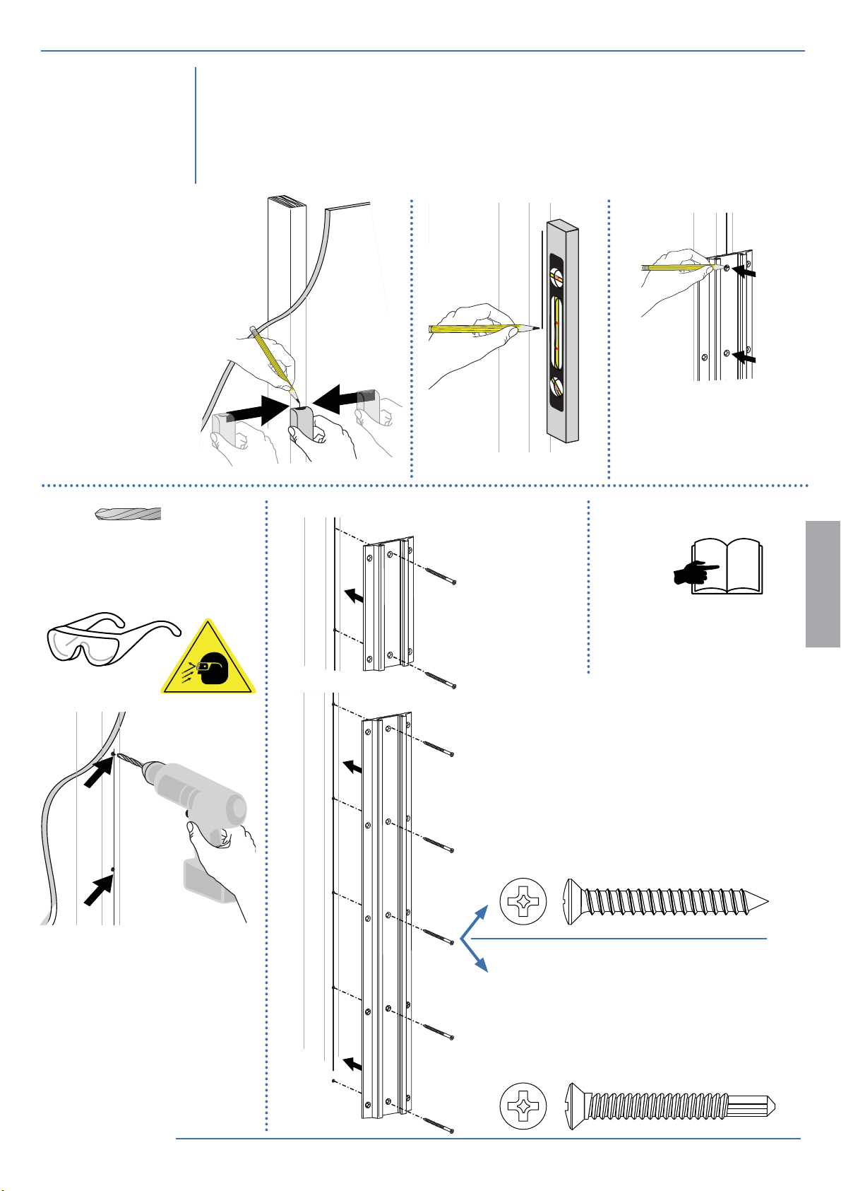
Wood
Madera
2
Solide Holzbalkenträger
Massief Houten Pilaren
Due montanti in legno massiccio
Bois
木
木质
나무
Studs ≥ 25 gauge steel
Pernos de acero de calibre ≥ 25
Goujons ≥ calibre25 en acier
Bolzen ≥ Blechlehre Nr. 25
Verbindingsbouten ≥ 25 gauge staal
Prigionieri in acciaio spessore ≥ gauge 25 (0,556 mm)
Reglar ≥ 25-gauge stål
25ゲージのスチールよりも強力なスタッド
板墙筋为不小于 25 标号的钢材
a
d
Stud Finder
Ø 3/16" (5 mm)
e f
c b
3
ENGLISH
9
x 5
888-45-277-W-03 rev.J • 02/17
Wood Stud Mounting
7x
Studs ≥ 25 gauge steel
Pernos de acero de calibre ≥ 25
Goujons ≥ calibre25 en acier
Bolzen ≥ Blechlehre Nr. 25
Verbindingsbouten ≥ 25 gauge staal
Prigionieri in acciaio spessore ≥ gauge 25 (0,556 mm)
Reglar ≥ 25-gauge stål
25ゲージのスチールよりも強力なスタッド
板墙筋为不小于 25 标号的钢材
7x
7 of 28
Page 8
2
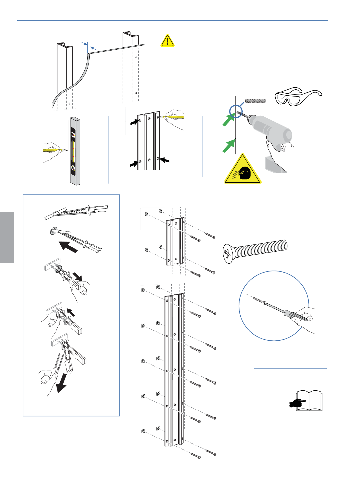
Hollow Wall
Pared
Mur
Wand
Muur
Parete
壁
墙壁
≥ 5/8”
Sheetrock
Sheetrock
Plaque de plâtre
Rigipsplatte
Sheetrock
Cartongesso
Gipsskiva
シートロック
石膏板
Requires minimum material thickness of 5/8” (16 mm).
Requiere un grosor mínimo de 16 mm.
Epaisseur minimum de 16 mm.
Requer uma espessura mínima de 5/8” (16 mm).
Mit einer Materialdicke von mindestens 16 mm.
Vereist een minimale materiaaldikte van 1.6 cm.
Richiede uno spessore del materiale non inferiore a 16 mm.
厚さが最低 5/8” (16 mm) の資材が必要。
需要最低材料厚度为 5/8”(16 mm).
Ø 1/2"
(12.7 mm)
a
d
ENGLISH
14x
1
2
bc
e
14x
1/4-20 x 2"
8 of 28
3
4
f
3
888-45-277-W-03 rev.J • 02/17
9
Page 9
3
a b c d
2x
M10 x 16mm
1x
1/8"
ef g
12x
2x
6mm
1x
ENGLISH
Security Feature
Función de seguridad
Fonction de sécurité
Sicherheitsmerkmal
Beveiligingsfunctie
Dispositivo antifurto
セキュリティ機能
安全特性
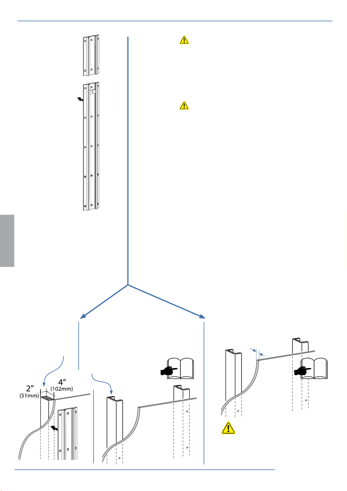
2x
7/16"
2" - 4"
(51 - 102 mm)
1x
1x
4" - 8"
(102 - 203 mm)
888-45-277-W-03 rev.J • 02/17
10
4
9 of 28
Page 10

4
a
b
8x
1/4-20 x 1/2"
Optional locking feature
c
(customer supplied lock)
d
8x
10-24 x 1/2"
NOTE: Fasteners may unwind due to vibration caused by movement of mounting solution
over time. Inspect mounting solution for loose fasteners on a routine basis. If desired, apply a
ENGLISH
light duty thread locking adhesive to fasteners before installation to prevent back-out.
NOTE: The mounting bracket can be relocated vertically on the
wall track by loosening the the four wall plate screws.
10 of 28
888-45-277-W-03 rev.J • 02/17
Page 11

5
Mount extension and LCD arm to wall bracket.
c
b
a
NOTE: when
sliding sleeve
on to bracket,
align slot over
rotation stop.
Do Not
Overtighten
Cap Screw!
M6 x 45mm
4mm
Top View
ENGLISH
M6
M6
M6 x 45mm
4mm
+=
Do Not
Overtighten
Cap Screw!
888-45-277-W-03 rev.J • 02/17
Rotation Stop
on Bracket
Slot
in Sleeve
Sleeve on
Bracket
11 of 28
Page 12

5
Portrait / Landscape Options
OPTION i If you want full portrait/landscape rotation, skip to step 8 on the next page.
OPTION ii If you do not want your TV/Monitor to rotate all all, you can stop rotation by inseting
the set screw.
iii
ENGLISH
0˚
M3 x 6mm
12 of 28
7
13
888-45-277-W-03 rev.J • 02/17
Page 13

Check size of
7
TV/Monitor hole
pattern
A
75x75mm
100x100mm
14
B
100x200mm
TV/Monitor Hole
Pattern Sizes
VESA Adapter
Con gurations
100mm (3-15/16”)
75mm (2-15/16”)
100mm (3-15/16”)
100mm (3-15/16”)
75mm (2-15/16”)
200mm (7-7/8”)
C
ENGLISH
15
200mm (7-7/8”)
200mm (7-7/8”)
200x200mm
15
200mm (7-7/8”)
D
888-45-277-W-03 rev.J • 02/17
200x100mm
100mm (3-15/16”)
15
13 of 28
Page 14

7
Mount Type A TV/Monitor to Arm
75x75mm
100x100mm
A
4x
M4 x 10mm
100mm (3-15/16”)
75mm (2-15/16”)
ENGLISH
100mm (3-15/16”)
75mm (2-15/16”)
M4 x 10mm
14 of 28
OR
M4 x 10mm
17
8
888-45-277-W-03 rev.J • 02/17
Page 15

7
Mount VESA Adapters to Arm based on TV/Monitor hole
pattern size (B, C, or D) .
BCD
4x
M5 x 7mm
ENGLISH
888-45-277-W-03 rev.J • 02/17
15 of 28
Page 16

7
Mount Type B, C, or D TV/Monitor to Arm
B
100mm (3-15/16”)
200mm (7-7/8”)
C
200mm (7-7/8”)
200mm (7-7/8”)
D
200mm (7-7/8”)
100mm (3-15/16”)
ENGLISH
NOTE: To reduce M8
holes for use with M5
screws, or if you have a
model with Samsung
holder rings, follow the
M8M5 KIT instructions
on the next page.
OR
OR
M4x12mm
16 of 28
17
M5x12mm
M6x12mm
17
8
888-45-277-W-03 rev.J • 02/17
Page 17

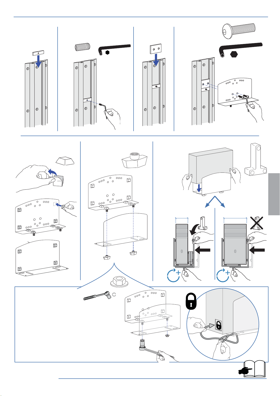
M8M5 KIT Instructions
NOTE: follow this step only if your TV/monitor has M8 holes which need to be reduced
to M5 or for Samsung models using the holder ring.
Install M8M5 reducer bushing to TV/Monitor and use M5 x 20 mm
monitor screws to secure when using the Samsung holder ring.
TV/Monitor Mounting
M8 size hole
Attach top
8
and bottom
bracket
covers
M5 x 20mm
Monitor Screw
M8M5 Reducer Bushing
Holder Ring
(Not included *Samsung Only)
To remove covers:
a) Wedge the blade of a at screwdriver into the gap between the wall mount bracket and the cover.
Rotate the blade upward to pry the cover away.
b) Repeat on the opposite side of the wall mount bracket.
c) Once the cover is free on both sides, lift it o .
Top Cover
Bottom Cover
ENGLISH
888-45-277-W-03 rev.J • 02/17
aa
bb
cc
17 of 28
Page 18

9
Mount extension and LCD arm to wall bracket.
ENGLISH
b
c
4x
M4 x 8mm
Do Not
Overtighten
Cap Screw!
a
NOTE: when
sliding sleeve
on to bracket,
align slot over
rotation stop.
Do Not
Overtighten
Cap Screw!
M6
M6 x 45mm
4mm
Top View
Rotation Stop
on Bracket
M6
M6 x 45mm
4mm
+=
Slot
in Sleeve
Sleeve on
Bracket
18 of 28
888-45-277-W-03 rev.J • 02/17
Page 19

10
a
c
b
4x
ENGLISH
d
888-45-277-W-03 rev.J • 02/17
19 of 28
Page 20

11
Attach top and
bottom bracket
covers
To remove covers:
a) Wedge the blade of a at screwdriver into the gap between the wall mount bracket and the cover.
Rotate the blade upward to pry the cover away.
b) Repeat on the opposite side of the wall mount bracket.
c) Once the cover is free on both sides, lift it o .
Top Cover
Bottom Cover
aa
bb
ENGLISH
12
a
cc
CABLE ROUTING
20 of 28
888-45-277-W-03 rev.J • 02/17
Page 21

12
CABLE ROUTING
b
Leave Slack in cable
c
ENGLISH
888-45-277-W-03 rev.J • 02/17
21 of 28
Page 22

13
CABLE ROUTING
a
Ø 7/32" (5.6 mm)
b
12 3
M4.2 x 25mm
ENGLISH
14
dcbe
fg
M4.2 x 25mm
abd e
22 of 28
c
888-45-277-W-03 rev.J • 02/17
Page 23

15
a
CABLE ROUTING
1x
Leave Slack in cable
1x
b
ENGLISH
c
888-45-277-W-03 rev.J • 02/17
23 of 28
Page 24

16
Important! You will need to adjust this product after installation is complete. Make sure all your equipment is
properly installed on the product before attempting adjustments. This product should move smoothly and easily
through the full range of motion and stay where you set it. If movements are too easy or diffi cult or if product
does not stay in desired positions, follow the adjustment instructions to create smooth and easy movements.
Depending on your product and the adjustment, it may take many turns to notice a difference. Any time
equipment is added or removed from this product, resulting in a change in the weight of the mounted load, you
should repeat these adjustment steps to ensure safe and optimum operation.
Lift – Up and down
Adjustment Step
a
5mm
ENGLISH
CAUTION: DO NOT overtighten fasteners.
Overtightening may cause damage to your
equipment.
WARNING
5mm
Increase Lift Strength
If the mounted weight is too heavy or
this product does not stay up when
raised, then you'll need to increase
Lift Strength:
Decrease Lift Strength
If the mounted weight is too light or
this product does not stay down when
lowered, then you'll need to decrease
Lift Strength:
WARNING
WARNING! Stored Energy Hazard: The arm mechanism is under tension and will move up rapidly, on its own, as
soon as attached equipment is removed. For this reason, DO NOT remove equipment unless the arm has been
moved to the highest position! Failure to follow this instruction may result in serious personal injury and/or
equipment damage!
24 of 28
888-45-277-W-03 rev.J • 02/17
Page 25

b
Lift – Up and down
CAUTION: DO NOT overtighten fasteners.
Overtightening may cause damage to your
equipment.
WARNING
ENGLISH
5mm
Increase Lift Strength
If the mounted weight is too heavy or
this product does not stay up when
raised, then you'll need to increase
Lift Strength:
Decrease Lift Strength
If the mounted weight is too light or
this product does not stay down when
lowered, then you'll need to decrease
Lift Strength:
WARNING
WARNING! Stored Energy Hazard: The arm mechanism is under tension and will move up rapidly, on its own, as
soon as attached equipment is removed. For this reason, DO NOT remove equipment unless the arm has been
moved to the highest position! Failure to follow this instruction may result in serious personal injury and/or
equipment damage!
888-45-277-W-03 rev.J • 02/17
25 of 28
Page 26

c
Tilt – Forward and Backward
ENGLISH
CAUTION: DO NOT remove screw. Removing
screw may cause damage to equipment.
4mm
4mm
Increase Lift Strength
If the mounted weight is too heavy or
this product does not stay up when
raised, then you'll need to increase
Lift Strength:
Decrease Lift Strength
If the mounted weight is too light or
this product does not stay down when
lowered, then you'll need to decrease
Lift Strength:
26 of 28
888-45-277-W-03 rev.J • 02/17
Page 27

How to remove this tilting feature:
3°3°
Save these screws incase you want to add
this feature later.
2x
ENGLISH
M4 x 14mm
888-45-277-W-03 rev.J • 02/17
27 of 28
Page 28

Set Your Workstation to Work For YOU!
Learn more about ergonomic computer use at:
www.computingcomfort.org
Height Position top of screen slightly below eye level.
Position keyboard at about elbow height with wrists at.
Distance Position screen an arm's length from face—at least 20” (508mm).
Position keyboard close enough to create a 90˚ angle in elbow.
Angle Tilt screen to eliminate glare.
Tilt the keyboard back 10° so that your wrists remain at.
To Reduce Fatigue
Breathe - Breathe deeply through your nose.
Blink - Blink often to avoid dry eyes.
Break • 2 to 3 minutes every 20 minutes
• 15 to 20 minutes every 2 hours.
ENGLISH
For Warranty visit: www.ergotron.com/warranty
For Service visit: www.ergotron.com
For local customer care phone numbers visit: http://contact.ergotron.com
28 of 28
© 2015 Ergotron, Inc. All rights reserved.
888-45-277-W-03 rev.J • 02/17
 Loading...