

Page 1
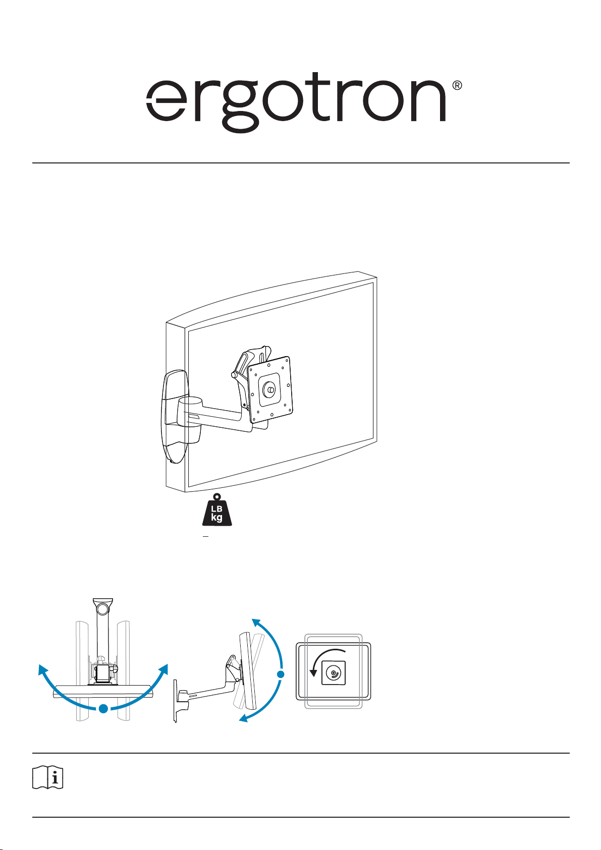
User's Guide
LX HD Wall Mount Swing Arm
< 50 lbs. (22.7 kg)
Features & Specifi cations
- 5˚
+ 15˚
For the latest User Installation Guide please visit: www.ergotron.com
English, Español, Français, Deutsch, Nederlands, Italiano, Svenska, 日本語, 汉语
www.ergotron.com |
888-45-200-W-01 rev.C • 12/18
USA: 1-800-888-8458
|
Europe: +31 (0)33-45 45 600
|
China: 400-120-3051
English
|
Japan: japansupport@ergotron.com
1 of 13
Page 2
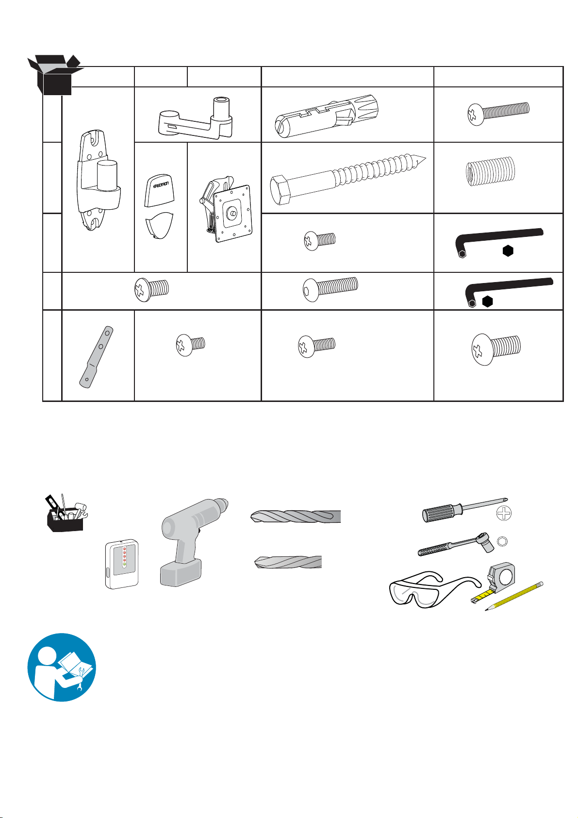
Components
ABC D E
1
2
3
4
5
1x
4x
1x
1x
1x
M4 x 8mm
4x
M5 x 7mm
1x
2x
2x
4x
4x
4x
M8 x 80mm
M4 x 12mm
10-24 x 5/8"
M5 x 12mm
4x
M5 x 20mm
4x
M8M5 Converter
1x
2.5mm
1x
1/8"
4x
M6 x 12mm
Tools Needed
Stud Finder
Important! You will need to adjust this product after installation is complete. Make sure all your equipment
is properly installed on the product before attempting adjustments. This product should move smoothly
and easily through the full range of motion and stay where you set it. If movements are too easy or
diffi cult or if product does not stay in desired positions, follow the adjustment instructions to create
smooth and easy movements. Depending on your product and the adjustment, it may take many turns to
notice a difference. Any time equipment is added or removed from this product, resulting in a change in
the weight of the mounted load, you should repeat these adjustment steps to ensure safe and optimum
operation.
Concrete Wall Mounting
Ø 3/8” (10mm)
Wood Stud Mounting
Ø 3/16" (5mm)
13mm
2
1
2 of 13
888-45-200-W-01 rev.C • 12/18
Page 3
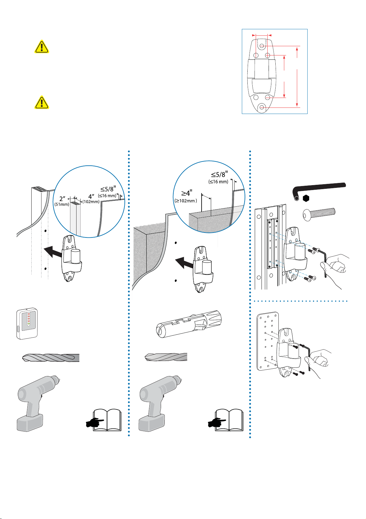
WALL PLATE MOUNTING INSTRUCTIONS
1
WARNING:
Ensure that the wall structure is capable of supporting four times the
total weight of mounted equipment. Mounting to wall surfaces that
do not meet this criteria may result in an unstable, unsafe condition
which could lead to personal injury and/or property damage. Consult a
construction professional if you have any doubt about what this means
in regard to your particular application.
NOTE: Fasteners may unwind due to vibration caused by movement of mounting
solution over time. Inspect mounting solution for loose fasteners on a routine basis. If
desired, apply a light duty thread locking adhesive to fasteners before installation to
prevent back-out.
1.125"
(28.6mm)
4.1"
(104mm)
6"
(152mm)
Wood
Stud Finder
Concrete
Ergotron product
1/8"
4x
10-24 x 5/8"
Concrete Wall Mounting
Ø 3/8” (10mm)
888-45-200-W-01 rev.C • 12/18
3
Wood Stud Mounting
Ø 3/16" (5mm)
NOTE: Wall Track and Brackets sold separately.
4
3 of 13
Page 4
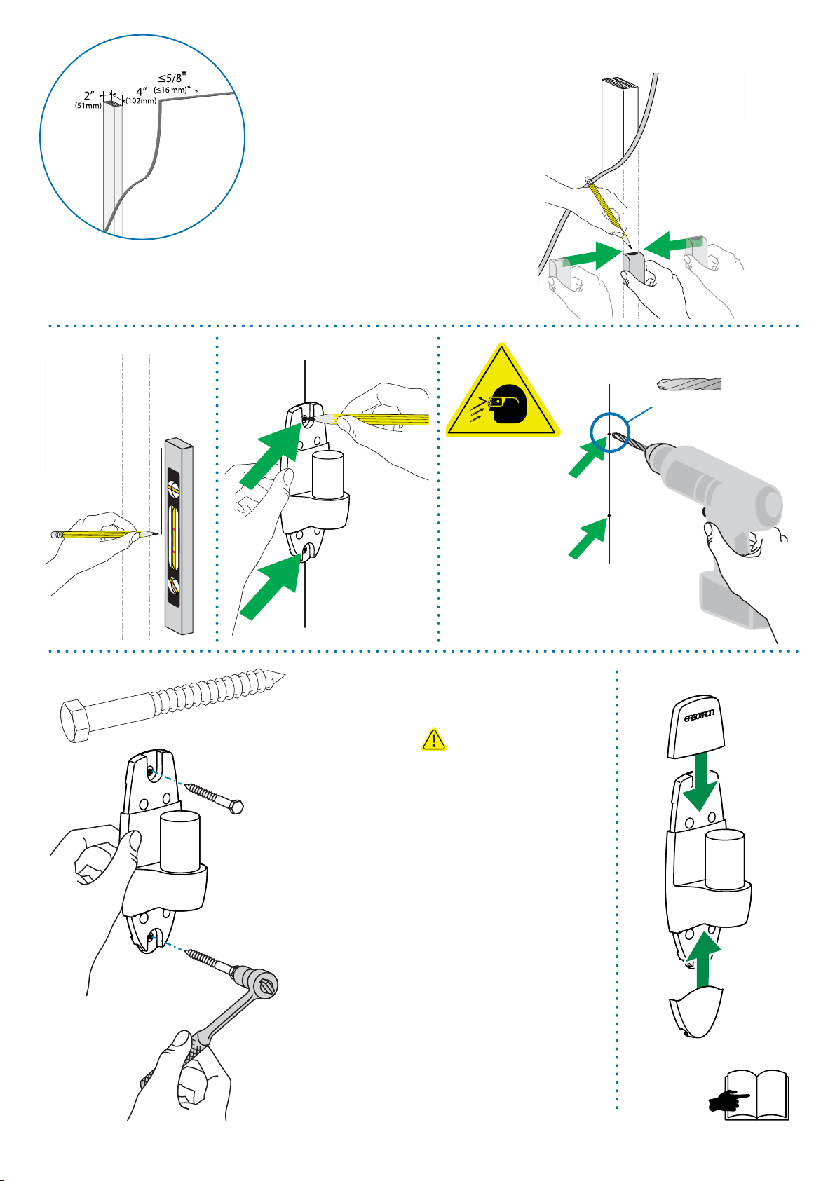
Wood
a
bc
2x
d
Ø 3/16"
(5 mm)
ef
M8 x 80mm
CAUTION: Make sure the wall mount bracket is level,
ush and snug to the wall surface. DO NOT OVERTIGHT-
EN THE BOLTS.
4 of 13
13 mm
6
888-45-200-W-01 rev.C • 12/18
Page 5

a
Wood Stud Mounting
c
b
Ø 3/8"
(10 mm)
Mounting holes must be at least 3-1/8” (80mm) deep and must be located within
WARNING:
solid concrete, not mortar or covering material. If you drill into an area of concrete
that is not solid, reposition mounting holes until both anchors can be fully inserted
into solid concrete!
3-1/8"
(80 mm)
888-45-200-W-01 rev.C • 12/18
5 of 13
Page 6

1
2
Wood Stud Mounting
2x
M8 x 80mm
d
2x
ef
13 mm
CAUTION: Make sure the wall mount bracket is level, ush and
snug to the wall surface. DO NOT OVERTIGHTEN THE BOLTS.
Anchors that are not fully set in solid concrete will not support the
applied load resulting in an unstable, unsafe condition which could
lead to personal injury and/or property damage. Consult a construction
professional if you have any doubt about what this means in regard to
WARNING:
your particular situation.
6
6 of 13
888-45-200-W-01 rev.C • 12/18
Page 7

2
360° 0°
Check size of
3
TV/Monitor hole
pattern
To Stop Portrait/Landscape Rotation
insert Screw
M4 x 8mm
TV/Monitor Hole
Pattern Sizes
VESA Adapter
Con gurations
100mm (3-15/16”)
75mm (2-15/16”)
100mm (3-15/16”)
75mm (2-15/16”)
A
B
C
75x75mm
100x100mm
8
100x200mm
9
200x200mm
9
100mm (3-15/16”)
200mm (7-7/8”)
200mm (7-7/8”)
200mm (7-7/8”)
888-45-200-W-01 rev.C • 12/18
D
200x100mm
9
200mm (7-7/8”)
100mm (3-15/16”)
7 of 13
Page 8

3
Mount Type A TV/Monitor to Arm
A
75x75mm
100x100mm
100mm (3-15/16”)
75mm (2-15/16”)
100mm (3-15/16”)
75mm (2-15/16”)
75 x 75mm
4x
M4 x 12mm
100 x 100mm
4x
M4 x 12mm
8 of 13
4
888-45-200-W-01 rev.C • 12/18
11
Page 9

100x200mm 200x200mm 200x100mm
B
100mm (3-15/16”)
C
D
200mm (7-7/8”)
200mm (7-7/8”)
3a
200mm (7-7/8”)
200mm (7-7/8”)
Mount VESA Adapters to Arm based on TV/Monitor hole
pattern size (B, C, or D) .
4x
M5 x 7mm
100mm (3-15/16”)
3b
NOTE: To reduce M8
holes for use with M5
screws, or if you have a
model with Samsung
holder rings, follow the
M8M5 KIT instructions
on the next page.
Mount Type B, C, or D TV/Monitor to Arm
10
4x4x 4x
M4 x 12mm M5 x 12mm M6 x 12mm
888-45-200-W-01 rev.C • 12/18
9 of 13
Page 10

M8M5 KIT Instructions
NOTE: Follow this step only if your TV/monitor has M8 holes which need to be
reduced to M5.
Install M8M5 reducer bushing to TV/Monitor and use M5 x 20 mm monitor
screws to secure.
4x
TV/Monitor Mounting
M8 size hole
NOTE: Follow this step only for Samsung models using the holder ring.
Install M8M5 reducer bushing to TV/Monitor then use M5 x 20 mm monitor screws
and Samsung holder ring to secure.
4x
M5 x 20mm
TV/Monitor Mounting
M8 size hole
10 of 13
4x
4x
M5 x 20mm
Holder Ring
(Not included *Samsung Only)
888-45-200-W-01 rev.C • 12/18
Page 11

4
ATTACH TO WALL MOUNT BRACKET
Cable Routing
888-45-200-W-01 rev.C • 12/18
11 of 13
Page 12

5
Adjustment Step
Important! You will need to adjust this product after installation is complete. Make sure all your equipment is
properly installed on the product before attempting adjustments. This product should move smoothly and easily
through the full range of motion and stay where you set it. If movements are too easy or diffi cult or if product
does not stay in desired positions, follow the adjustment instructions to create smooth and easy movements.
Depending on your product and the adjustment, it may take many turns to notice a difference. Any time
equipment is added or removed from this product, resulting in a change in the weight of the mounted load, you
should repeat these adjustment steps to ensure safe and optimum operation.
Tilt – Forward and Backward
a
Arm Swing – Side-to-side
b
+ 15˚
- 5˚
Loosen knob, tilt Display to desired position then retighten knob.
2.5mm
< 180˚
Increase Friction
If this product moves too easily, then
you'll need to increase friction:
Decrease Friction
If this product is too diffi cult to move,
then you'll need to decrease friction:
12 of 13
888-45-200-W-01 rev.C • 12/18
Page 13

Pan – Side-to-side
c
2.5mm
Increase Friction
If this product moves too easily, then
you'll need to increase friction:
Decrease Friction
If this product is too diffi cult to move,
then you'll need to decrease friction:
< 180˚
Set Your Workstation to Work For YOU!
Learn more about ergonomic computer use at:
www.computingcomfort.org
Height Position top of screen slightly below eye level.
Position keyboard at about elbow height with wrists fl at.
Distance Position screen an arm's length from face—at least 20” (508mm).
Position keyboard close enough to create a 90˚ angle in elbow.
Angle Tilt screen to eliminate glare.
Tilt the keyboard back 10° so that your wrists remain fl at.
To Reduce Fatigue
Breathe - Breathe deeply through your nose.
Blink - Blink often to avoid dry eyes.
Break • 2 to 3 minutes every 20 minutes
• 15 to 20 minutes every 2 hours.
For Warranty visit: www.ergotron.com/warranty
For Service visit: www.ergotron.com
For local customer care phone numbers visit: http://contact.ergotron.com
NOTE: When contacting customer service, reference the serial number.
www.ergotron.com |
© 2014 Ergotron, Inc. All rights reserved.
USA: 1-800-888-8458
|
Europe: +31 (0)33-45 45 600
|
China: 400-120-3051
|
Japan: japansupport@ergotron.com
888-45-200-W-01 rev.C • 12/18
13 of 13
 Loading...