

Page 1
User's Guide
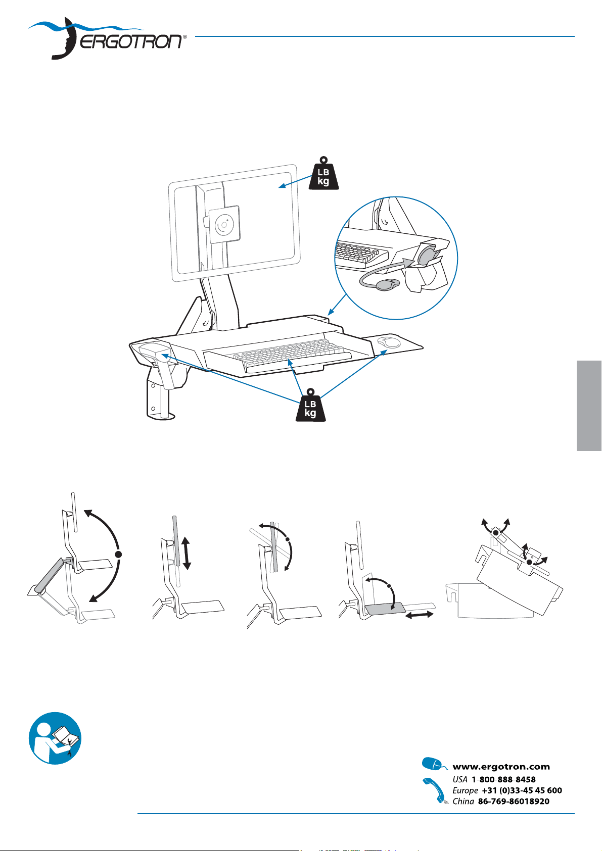
StyleView Sit Stand Combo Arm,
with Worksurface
6-18 lbs*
(2.7-8.2 kg)
1-4 lbs
(0.45-1.8 kg)
* The Combo Arm can be modi ed to mount displays up to 25 lbs (11.3 kg), however display lift and tilt motion will not be possible if
this option is chosen. Refer to special instructions on page 7.
20"
(508mm)
5"
(127mm)
25˚
5˚
90˚
8"
(202mm)
360˚
ENGLISH
180˚
For the latest User Installation Guide please visit: www.ergotron.com
User's Guide - English
Guía del usuario - Español
Manuel de l’utilisateur - Français
Gebruikersgids - Deutsch
Benutzerhandbuch - Nederlands
Guida per l’utente - Italiano
Användarhandbok - svenska
ユーザーガイド:日本語
用户指南 : 汉语
888-45-202-W-04 rev.K • 10/14
1 of 14
Page 2

Important! You will need to adjust this product after installation is complete. Make sure all your equipment is properly
installed on the product before attempting adjustments. This product should move smoothly and easily through the
full range of motion and stay where you set it. If movements are too easy or diffi cult or if product does not stay in
desired positions, follow the adjustment instructions to create smooth and easy movements. Depending on your
product and the adjustment, it may take many turns to notice a difference. Any time equipment is added or removed
from this product, resulting in a change in the weight of the mounted load, you should repeat these adjustment steps
to ensure safe and optimum operation.
Components
1x
1
ENGLISH
2
3
4
1x
1x
1x
2x
1x
ABC D
1x
1x
1x
1x 1x
2x
1x
M6 x 10mm
M8 x 16mm
1x
1x
1x
6 mm
3 mm
8mm
2x
1x
1x
M5 x 15mm
4x
4x
4x
M4 x 10mm
4x
M10 x 18mm
1x
M3.5 x 8mm
2x
1x
4x
M4 x 10mm
2x
7x
7x
1x
Optional Weight Capacity Modi cation Fasteners
M4 x 10mm
M4 x 8mm
2x
Tools Needed
2
1
2 of 14
M4 x 6mm
11 mm
13 mm
1/4”
888-45-202-W-04 rev.K • 10/14
Page 3
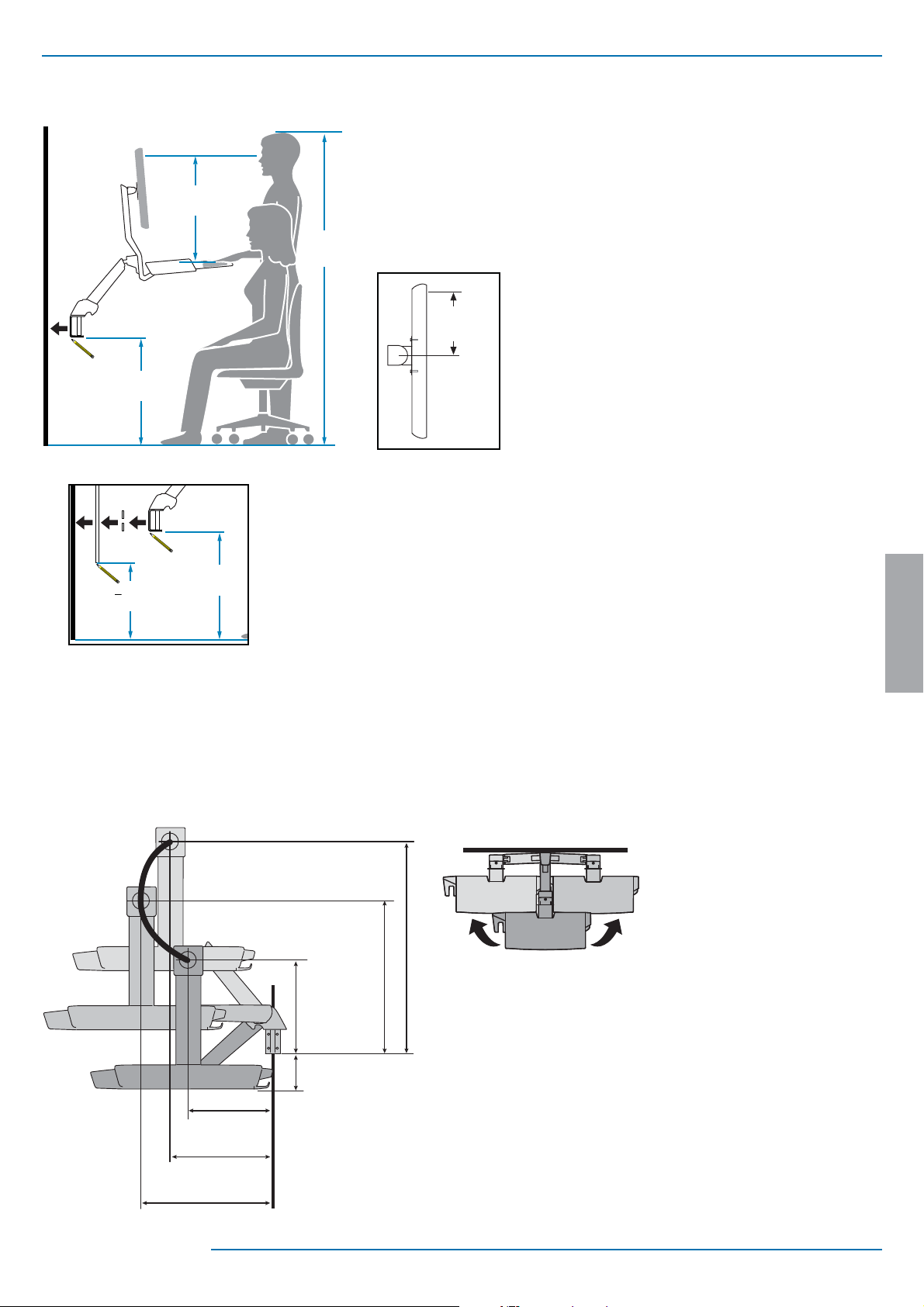
Mounting Height for Ergonomic Workstation
1
This mounting height is a recommendation for an ergonomic workstation
that accommodates user heights of 5’3”-5’9” (160-175cm).
21”
(533 mm)
5’3”-5’9”
(160-175cm)
28.5”
(724mm)
Wall Track Applications
If user heights are di erent than this, you should change mounting height
to accommodate user heights. (Change mounting height one inch for every
one inch di erence in user heights).
6”
(152 mm)
Mounting height assumes there is a 6” (152 mm) distance
between the center of your monitor mounting holes
and the top of the screen. If your distance is smaller, you
should increase mounting height accordingly, if your
distance is larger, you should decrease your mounting
height accordingly.
28.5”
< 27.5”
(699mm)
(724mm)
Determine mounting location:
Front view with arm pushed back against the wall.
(575mm)
11.9”
(301mm)
ENGLISH
Top view showing range of motion when pulled out from the wall.
31.9”
(810mm)
22.7”
(318mm)
(430mm)
888-45-202-W-04 rev.K • 10/14
9.2”
(232mm)
12.5”
17”
9.5”
(241mm)
3 of 14
Page 4
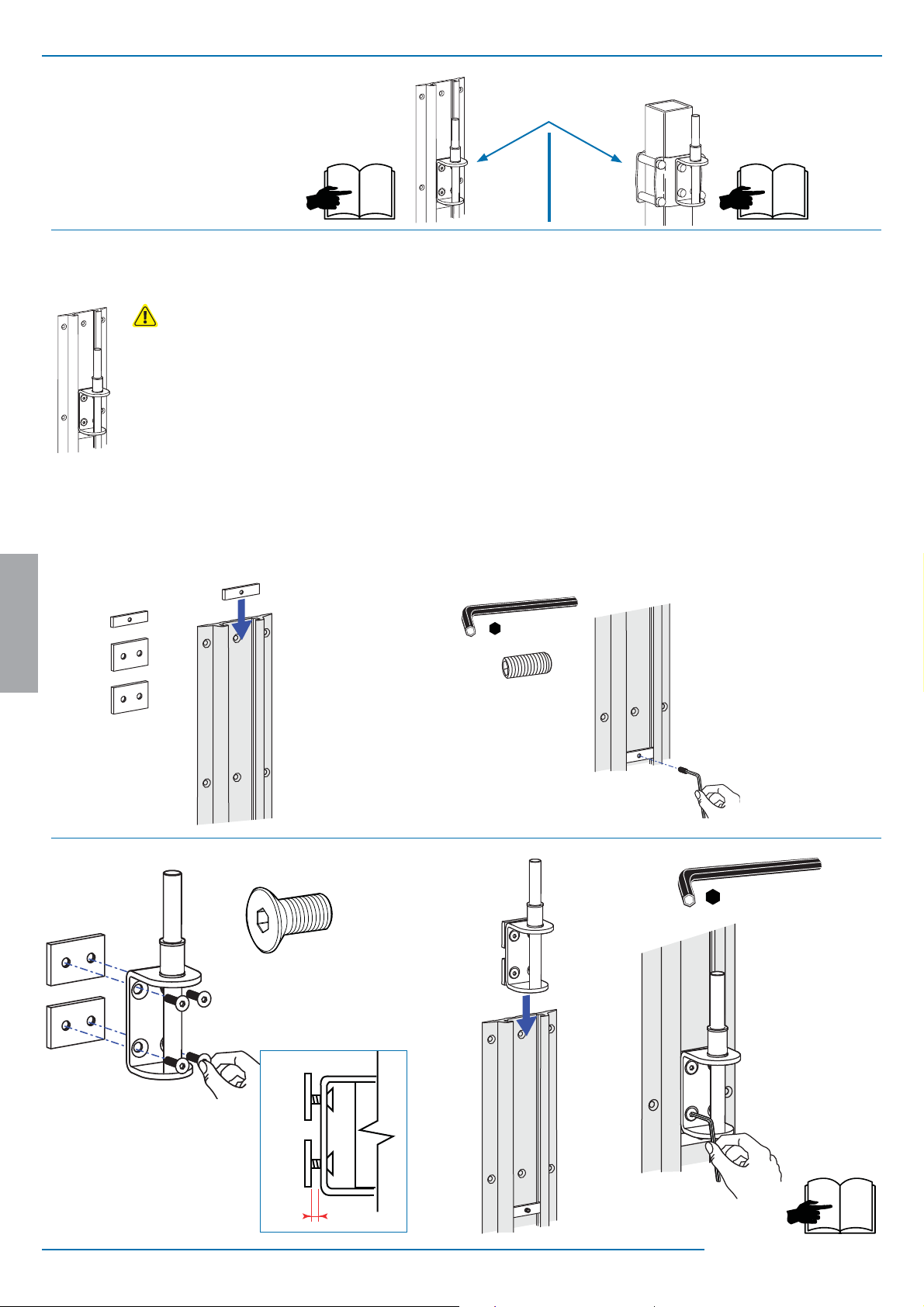
Choose Mounting Solution (sold separately)
2
NOTE: Fasteners may unwind due to vibration caused by movement of mounting solution over time. Inspect mounting solution
for loose fasteners on a routine basis. If desired, apply a light duty
thread locking adhesive to fasteners before installation to prevent
back-out.
2
54
a
ENGLISH
c
4x
M10 x 18mm
b
1x
M6 x 10mm
d
3 mm
e
6 mm
4 of 14
¼"
6
888-45-202-W-04 rev.K • 10/14
Page 5
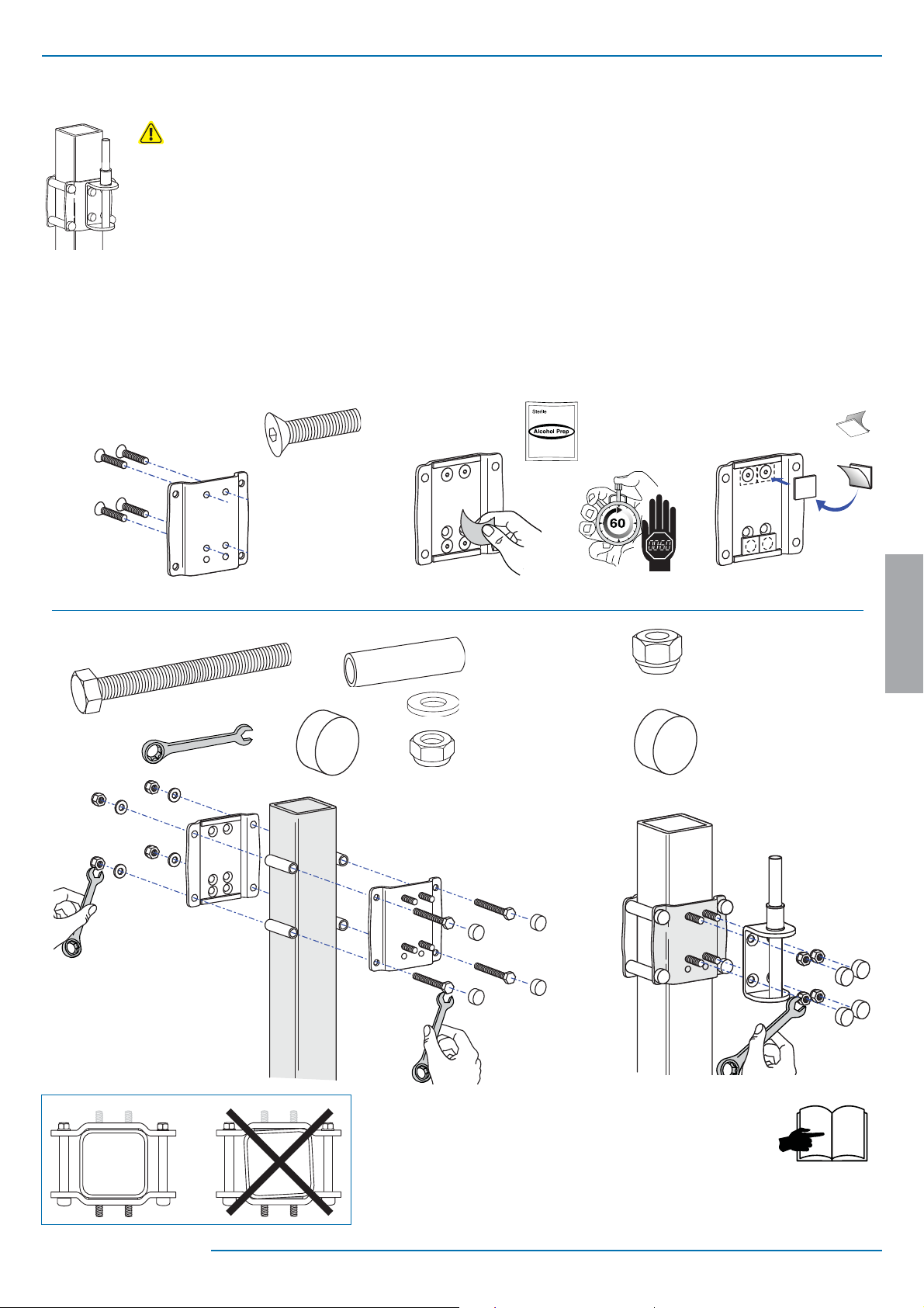
2
a
NOTE: Fasteners may unwind due to vibration caused by movement of mounting solution over time. Inspect mounting solution
for loose fasteners on a routine basis. If desired, apply a light duty
thread locking adhesive to fasteners before installation to prevent
back-out.
4x
3/8-16 x 3/4"
b
4x
c d
4x
3/8-16 x 3-1/2"
4x
9/16"
4x
4x
4x
3/8" nylock nut
ENGLISH
4x
3/8" lug nut
4x
888-45-202-W-04 rev.K • 10/14
6
5 of 14
Page 6

3
1x
M8 x 16mm
1x
1x
1x
1x
13 mm
ENGLISH
4
2x
M5 x 15mm
3 mm
6 of 14
888-45-202-W-04 rev.K • 10/14
Page 7

Optional Weight Capacity Modi cation
Optional Weight Capacity Modi cation for Displays 18 - 25 lbs (8.2 - 11.3 kg) Only!
IMPORTANT: with this option display lift and tilt motion are no longer possible. To accomodate extra weight, the display is xed at one of three heights (spaced
2.5" (64 mm) apart), and display tilt is xed at 20°. If mounting a display 18 lbs (8.2 kg) or less, skip to next page.
1x
i
ii
M4 x 8mm
a c b
2x
M4 x 6mm
1x
ENGLISH
20˚
1x
888-45-202-W-04 rev.K • 10/14
7 of 14
Page 8

5
6
0˚
1x
M3.5 x 8mm
4x
4x
M4 x 10mm
ENGLISH
7
1x
2x
4x
8 of 14
888-45-202-W-04 rev.K • 10/14
Page 9

8
9
10
11
1x
NOTE: Leave enough slack in cable to allow full range of motion.
Caution:
To avoid the potential to pinch cables it is important to follow the cable routing instructions in this manual. Failure to
follow these instructions may result in equipment damage or personal injury.
2x
1x
ENGLISH
888-45-202-W-04 rev.K • 10/14
9 of 14
Page 10

12
NOTE: Make sure cables can slide in and out through
covers and cable channels.
2x
7x
5x
13
ENGLISH
OPTIONAL:
2x
14
M4 x 10mm
2x
10 of 14
888-45-202-W-04 rev.K • 10/14
Page 11

15
Important! You will need to adjust this product after installation is complete. Make sure all your equipment is
properly installed on the product before attempting adjustments. This product should move smoothly and easily
through the full range of motion and stay where you set it. If movements are too easy or diffi cult or if product
does not stay in desired positions, follow the adjustment instructions to create smooth and easy movements.
Depending on your product and the adjustment, it may take many turns to notice a difference. Any time
equipment is added or removed from this product, resulting in a change in the weight of the mounted load, you
should repeat these adjustment steps to ensure safe and optimum operation.
Adjustment Step
a
1/4”
8mm
Increase Lift Strength
If the mounted weight is too heavy or
this product does not stay up when
raised, then you'll need to increase
Lift Strength:
ENGLISH
Decrease Lift Strength
If the mounted weight is too light or
this product does not stay down when
lowered, then you'll need to decrease
Lift Strength:
888-45-202-W-04 rev.K • 10/14
11 of 14
Page 12

b
Lift – Up and down
11 mm
Increase Lift Strength
If the mounted weight is too heavy or
this product does not stay up when
raised, then you'll need to increase
Lift Strength:
Decrease Lift Strength
If the mounted weight is too light or
this product does not stay down when
lowered, then you'll need to decrease
Lift Strength:
ENGLISH
c
Tilt – Forward and Backward
Increase Lift Strength
If the mounted weight is too heavy or
this product does not stay up when
raised, then you'll need to increase
Lift Strength:
Decrease Lift Strength
If the mounted weight is too light or
this product does not stay down when
lowered, then you'll need to decrease
Lift Strength:
12 of 14
888-45-202-W-04 rev.K • 10/14
Page 13

d
Arm Swing – Side-to-side
Increase Friction
If this product moves too easily, then
you'll need to increase friction:
13 mm
Decrease Friction
If this product is too diffi cult to move,
then you'll need to decrease friction:
ENGLISH
e
3 mm
888-45-202-W-04 rev.K • 10/14
13 of 14
Page 14

Set Your Workstation to Work For YOU!
Learn more about ergonomic computer use at:
www.computingcomfort.org
Height Position top of screen slightly below eye level.
Position keyboard at about elbow height with wrists at.
Distance Position screen an arm's length from face—at least 20” (508mm).
Position keyboard close enough to create a 90˚ angle in elbow.
Angle Tilt screen to eliminate glare.
Tilt the keyboard back 10° so that your wrists remain at.
To Reduce Fatigue
Breathe - Breathe deeply through your nose.
Blink - Blink often to avoid dry eyes.
Break • 2 to 3 minutes every 20 minutes
• 15 to 20 minutes every 2 hours.
ENGLISH
For local customer care phone numbers visit: http://contact.ergotron.com
14 of 14
888-45-202-W-04 rev.K • 10/14
 Loading...