

Page 1
™
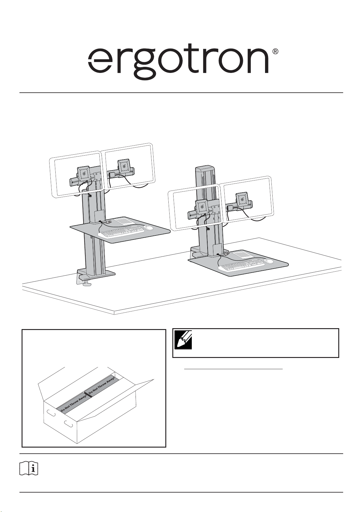
WorkFit
Dual Monitor
SR
User's Guide
Includes
Constant Force™
Technology
Do not throw away!
Cardboard blocks needed for
For the latest User Installation Guide please visit: www.ergotron.com
English, Español, Français, Deutsch, Nederlands, Italiano, Svenska, 日本語, 汉语
www.ergotron.com |
888-33-382-G-02 rev. F • 12/18
installation.
USA: 1-800-888-8458
|
NOTE: 10 feet of cable needed for proper
installation.Extra cables can be found at
www.ergotron.com
Visit http://www.ergotron.com/workfi t-sr-install for installation
instructional video.
Europe: +31 (0)33-45 45 600
|
China: 400-120-3051
|
English
Japan: japansupport@ergotron.com
1 of 20
Page 2
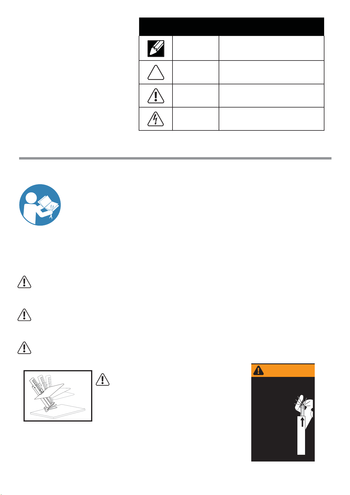
Hazard Symbols
Symbol Signal Word Level of Hazard
Review
These symbols alert users of a safety condition that demands attention. All users should
be able to recognize and understand the
signifi cance of the following Safety Hazards
if encountered on the product or within the
documentation. Children who are not able
to recognize and respond appropriately to
Safety Alerts should not use this product without adult supervision!
Safety
Important! You will need to adjust this product after installation is complete. Make sure all your
equipment is properly installed on the product before attempting adjustments. This product should
move smoothly and easily through the full range of motion and stay where you set it. If movements
are too easy or diffi cult or if product does not stay in desired positions, follow the adjustment
instructions to create smooth and easy movements. Depending on your product and the adjustment,
it may take many turns to notice a difference. Any time equipment is added or removed from this
product, resulting in a change in the weight of the mounted load, you should repeat these adjustment
steps to ensure safe and optimum operation.
NOTE
CAUTION
WARNING
ELECTRICAL
A NOTE indicates important information that helps you
make better use of this product.
A CAUTION indicates either potential damage to
hardware or loss of data and tells you how to avoid the
problem.
A WARNING indicates either potential for property damage, personal injury, or death.
An Electrical indicates an impending electrical hazard
which, if not avoided, may result in personal injury, re
and/or death.
Warning:
Because mounting surface materials can vary widely, it is imperative that you make sure mounting surface is strong enough to
handle mounted product and equipment.
Warning:
Follow the instructions in this manual to securely clamp this product to your mounting surface. Failure to do so may result in
equipment damage or personal injury.
Warning:
To avoid the potential to pinch cables it is important to follow the cable routing instructions in this manual. Failure to follow
these instructions may result in equipment damage or personal injury.
WARNING
STORED ENERGY HAZARD!
DO NOT OPEN TOWER OR REMOVE
Warning: Tipping Hazard. Support the stand until the clamp is securely
tightened. Failure to follow these instructions may result in the stand
tipping over causing possible equipment damages and or
personal injury.
SAFETY GUARD!
A primary mechanism within the
tower is under tension and can
be hazardous to people
exposed to it under certain
extreme conditions. DO NOT
open the tower; DO NOT attempt
to service the cart/stand. DO NOT
remove safety guards or labels
designed to protect or inform of
possible hazards. Only
Ergotron-approved installers may
service or otherwise modify
cart/stand. Failure to heed this
Warning may result in serious
Personal Injury and Damage both
to the cart/stand and equipment.
822-959-00
2 of 20
888-33-382-G-02 rev. F • 12/18
Page 3
2
1
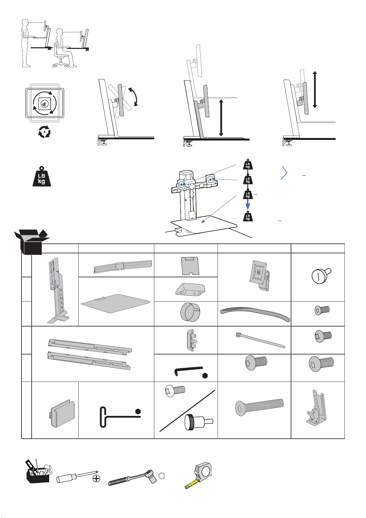
Features & Specifi cations
30°
CAUTION: DO NOT EXCEED MAXIMUM LISTED
WEIGHT CAPACITY. SERIOUS INJURY OR
PROPERTY DAMAGE MAY OCCUR!
18.25"
(463.55mm)
3 - 11 lbs
A
(1.3 - 5 kg)
3 - 11 lbs
B
(1.3- 5 kg)
< 5 lbs
C
(2.2 kg)
< 22 lbs (10 kg)
A+B
5"
(127mm)
A+B+C
< 25 lbs (11.4 kg)
Components
AB C D
1
1x
2
3
1x
1x
1x
4
1x
5
1x
1x
2x
2x
1x
2mm
2x
2x
8x
4x
M6 x 10mm
2x
M4 x 8mm
2x
M3 x 6mm
2x
M4 x 6mm
4x
M6 x 12mm
2x
6
Tools Needed
888-33-382-G-02 rev. F • 12/18
1x
4mm
M4 x 10mm
8x
10mm
8x
M4 x 10mm
1x
4x
M6 x 25mm
3 of 20
Page 4
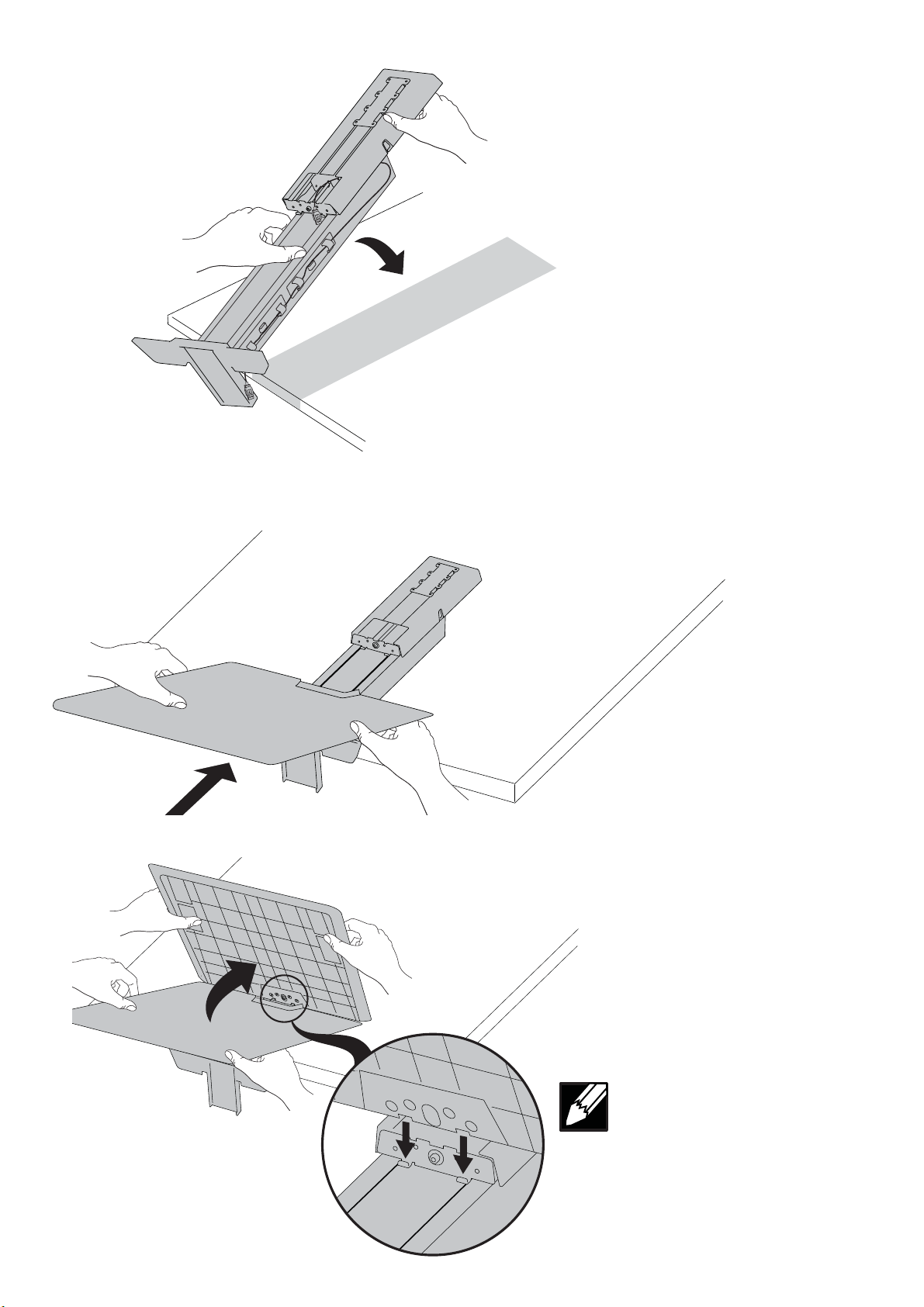
Lay engine down.
1
Attach worksurface to bottom of riser.
2
a
b
4 of 20
NOTE: Make sure slots align when
installing work surface.
888-33-382-G-02 rev. F • 12/18
Page 5
2
1
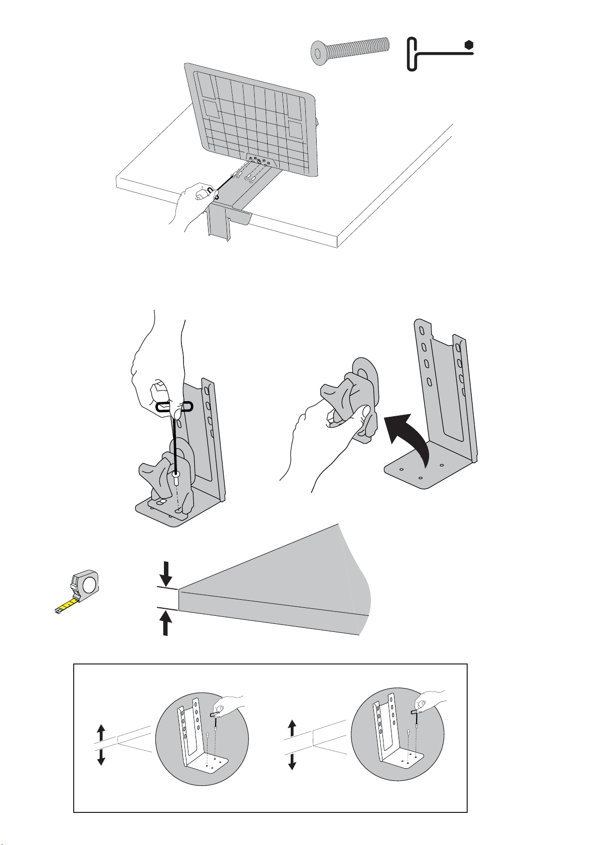
Screw worksurface into riser.
c
Disassemble desk clamp.
3
4mm
4x
M6 x 25mm
a
Remove two screws from clamp base. Remove clamp from clamp base.
Measure desk thickness.
c
b
Partially reinstall screws into clamp base.(1.5 revolutions)
d
888-33-382-G-02 rev. F • 12/18
Desk Thickness
.4" - 1.4"
(10mm - 36mm)
1.1" - 2.4"
(28mm - 61mm)
5 of 20
Page 6
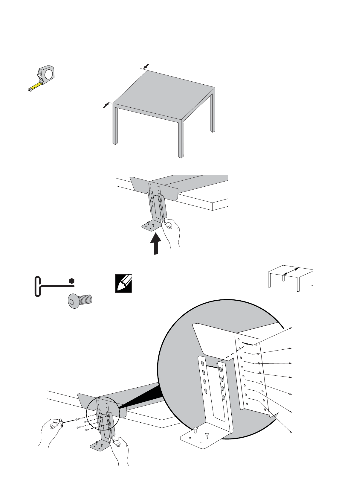
2
1
Secure clamp base to riser.
4
a
Measure desk depth.
b
Slide clamp base into bottom of riser.
Back
Front
Secure clamp base to riser.
c
4mm
4x
M6 x 12mm
NOTE: Align the clamp window with the
line on the bottom of the riser for your
desk depth.
Desk Depth
30”
(76cm)
31”
(79cm)
32”
( 81cm)
33”
( 84cm)
34”
(86cm)
35”
( 90cm)
36”
( 91cm)
6 of 20
888-33-382-G-02 rev. F • 12/18
Page 7

Mount to desk.
5
4mm
2x
a
Use cardboard blocks to support worksurface.
c
Two person lift.
b
Caution:
Worksurface not stable until
clamp is secured.
Secure clamp to clamp base.
d
888-33-382-G-02 rev. F • 12/18
7 of 20
Page 8

2"
(51mm)
2"
(51mm)
2"
(51mm)
Tighten clamp.
e
Caution: Follow the instructions in this manual
to securely clamp this product to your mounting
surface. Failure to do so may result in equipment
damage or personal injury.
NOTE: Push clamp base to edge of
mounting surface.
Remove cardboard blocks from
f
underneath work surface
Screw crossbar to riser.
6
4mm
4x
M6 x 10mm
8 of 20
NOTE: Crossbar can be mounted to
accommodate di erent heights.
888-33-382-G-02 rev. F • 12/18
Page 9

7
Slide cable routing clips onto crossbar.
2x
8
Lay monitor facedown on worksurface.
a
888-33-382-G-02 rev. F • 12/18
9 of 20
Page 10

OPTIONAL: Insert stop screw
to lock portrait/landscape
monitor rotation.
1x
M4x 6mm
0°
b
into mounting brackets.
1x
M4 x 8mm
Cable Routing
9
Plug power and video cables into monitor
a
by routing through cable clip.
c
Attach monitors to mounting brackets. Loosely thread thumb screws
4x
M4 x 10mm
4x
M4 x 10mm
10 of 20
888-33-382-G-02 rev. F • 12/18
Page 11

Route cables through cable clips on side
bc
of riser.
Check cable lengths.
Follow relief loop
when routing cables.
10
a
Slide monitor onto crossbar.
Make sure there is enough cable.
(10ft cable recommended)
NOTE: Monitor mounting
brackets can be installed upside
down to lower monitor 4".
888-33-382-G-02 rev. F • 12/18
11 of 20
Page 12

Center total width of mounted equipment on stand.
Tighten thumb screws to secure monitors.
b
2x
11
Attach end caps to crossbar.
a
2x
M3 x 6mm
1x
2mm
b
Secure end caps
to crossbar.
12 of 20
888-33-382-G-02 rev. F • 12/18
Page 13

12
a
Keyboard and Mouse cables
Route mouse and keyboard cables
b
through cable clips on side of riser.
Follow relief loop when
routing cables.
888-33-382-G-02 rev. F • 12/18
13 of 20
Page 14

13
Adjustment Step
Important! You will need to adjust this product after installation is complete. Make
sure all your equipment is properly installed on the product before attempting
adjustments. This product should move smoothly and easily through the full range of
motion and stay where you set it. If movements are too easy or diffi cult or if product
does not stay in desired positions, follow the adjustment instructions to create
smooth and easy movements. Depending on your product and the adjustment,
it may take many turns to notice a difference. Any time equipment is added or
removed from this product, resulting in a change in the weight of the mounted load,
you should repeat these adjustment steps to ensure safe and optimum operation.
Lift up and down.
a
10mm
STORED ENERGY HAZARD!
DO NOT OPEN TOWER OR REMOVE
A primary mechanism within the
tower is under tension and can
be hazardous to people
exposed to it under certain
extreme conditions. DO NOT
open the tower; DO NOT attempt
to service the cart/stand. DO NOT
remove safety guards or labels
designed to protect or inform of
possible hazards. Only
Ergotron-approved installers may
service or otherwise modify
cart/stand. Failure to heed this
Warning may result in serious
Personal Injury and Damage both
to the cart/stand and equipment.
Increase Lift Strength
If the mounted weight is too heavy or
this product does not stay up when
raised, then you'll need to increase
Lift Strength:
WARNING
SAFETY GUARD!
822-959-00
Lift up and down.
b
4mm
Decrease Lift Strength
If the mounted weight is too light or
this product does not stay down when
lowered, then you'll need to decrease
Lift Strength:
Adjustment may take up to: 72 full 360° revolutions
Increase Lift Strength
If the mounted weight is too heavy or
this product does not stay up when
raised, then you'll need to increase
Lift Strength:
Decrease Lift Strength
If the mounted weight is too light or
this product does not stay down when
lowered, then you'll need to decrease
Lift Strength:
14 of 20
Adjustment may take up to: 115 full 360° revolutions
888-33-382-G-02 rev. F • 12/18
Page 15

Pivot adjustment.
c
10mm
Increase Lift Strength
If the mounted weight is too heavy or
this product does not stay up when
raised, then you'll need to increase
Lift Strength:
14
Decrease Lift Strength
If the mounted weight is too light or
this product does not stay down when
lowered, then you'll need to decrease
Lift Strength:
Attach caps.
2x
NOTE: Align slot on cap with slot in mounting bracket
when installing caps.
888-33-382-G-02 rev. F • 12/18
15 of 20
Page 16

Test full range of motion
15
Lift riser to highest position.
a
Lower crossbar into lowest position.
b
NOTE: Leave enough slack in cable to allow full
range of motion.
Caution: To avoid the potential to pinch cables it is
important to follow the cable routing instructions in
this manual. Failure to follow these instructions may
result in equipment damage or personal injury.
16 of 20
888-33-382-G-02 rev. F • 12/18
Page 17

16
Wrap cables and fasten cable ties
Attach side panels.
17
4x2x
18
a
Attach front panel.
888-33-382-G-02 rev. F • 12/18
17 of 20
Page 18

b
19
Attach cap to top.
18 of 20
888-33-382-G-02 rev. F • 12/18
Page 19

How to align worksurface
to desk.
Follow these instructions if worksurface is not
aligned to desk properly after installation.
Loosen clamp.
a
Rotate Worfi t-SR so that worksurface is parallel to front edge of desk.
b
Top View
Secure clamp to desk.
c
888-33-382-G-02 rev. F • 12/18
19 of 20
Page 20

Set Your Workstation to Work For YOU!
Learn more about ergonomic computer use at:
www.computingcomfort.org
Height Position top of screen slightly below eye level.
Position keyboard at about elbow height with wrists fl at.
Distance Position screen an arm's length from face—at least 20” (508mm).
Position keyboard close enough to create a 90˚ angle in elbow.
Angle Tilt screen to eliminate glare.
Tilt the keyboard back 10° so that your wrists remain fl at.
To Reduce Fatigue
Breathe - Breathe deeply through your nose.
Blink - Blink often to avoid dry eyes.
Break • 2 to 3 minutes every 20 minutes
• 15 to 20 minutes every 2 hours.
For Warranty visit: www.ergotron.com/warranty
For Service visit: www.ergotron.com
For local customer care phone numbers visit: http://contact.ergotron.com
NOTE: When contacting customer service, reference the serial number.
www.ergotron.com |
© 2015 Ergotron, Inc. All rights reserved. WorkFit™ is a registered trademark of Ergotron, Inc.
USA: 1-800-888-8458
|
Europe: +31 (0)33-45 45 600
™
|
China: 400-120-3051
20 of 20
|
Japan: japansupport@ergotron.com
888-33-382-G-02 rev. F • 12/18
 Loading...