

Page 1
S
®
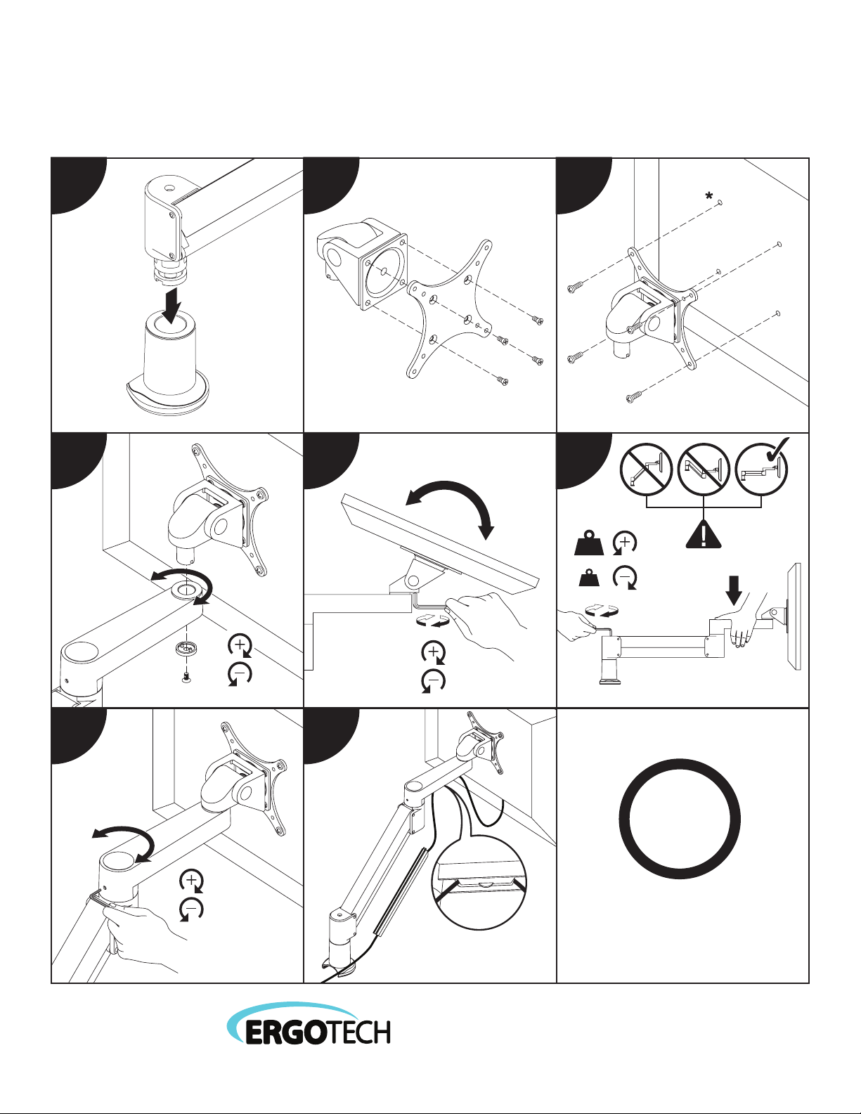
7FLEX
Installation Instructions
1 2 3
A
B
D
4 5
E
F
C
C
D
C
C
* Some monitor s may require a spac er hardware kit . See page 2 for d etails.
D
D
6
G
G
7 8
H
www.ergotechgroup.com
© 2017 Ergotech Group, LLC
INNOVATIVE ERGONOMIC SOLUTION
?
I
87 7.523.2767
www.ergotechgroup.com
PAGE 1 OF 5
P51 210 6 REV A
Page 2
S
®
7FLEX
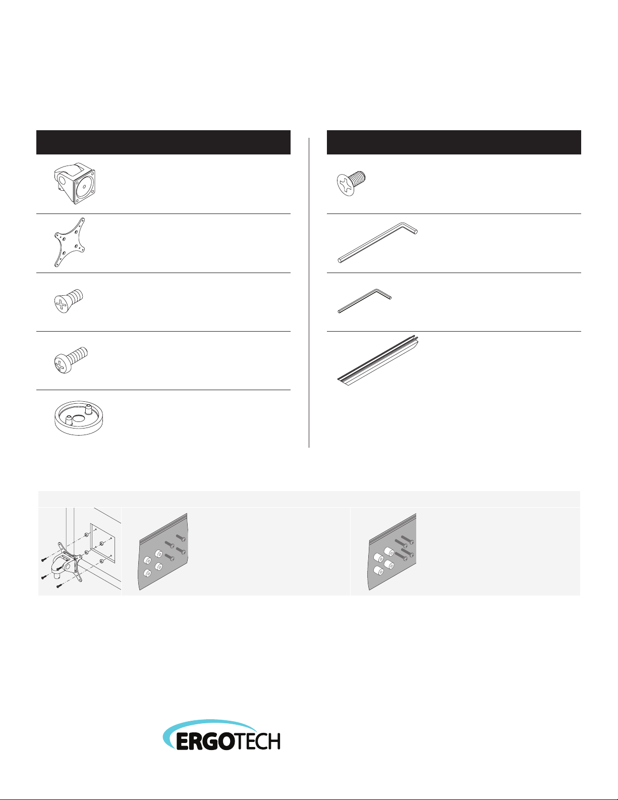
Installation Part List
ITEM DESCRIPTION / PART NO. QUANTITY ITEM DESCRIPTION / PART NO. QUANTITY
A Monitor Tilter 1
405397
B 75/100mm VESA® Adapter Plate 1
105587
C 10-32 x 3/8" Phillips Pan Head Screw 1
702281
D M4 x 12mm Phillips Pan Head Screw 1
702096
E Dog Washer 1
(4-pack)
(4-pack)
10 5189
F 10-32 x 3/8" FPhMS w/Lock Patch 1
70 5198
G 7/32" Allen Wrench 1
701127
H 3/32" Allen Wrench 1
70 014 6
I Cable Cap 1
1020 43 - 9.5
OPTIONAL SPACER KITS In some case s, the mounting su rface on your m onitor may be recess ed further tha n permitted by V ESA
.25" Spacer Hardware Kit
(4) .25" Spacers
(4) M4 x 18mm Phillips Pan Head Screws
Order # P404923-B
www.ergotechgroup.com
© 2017 Ergotech Group, LLC
INNOVATIVE ERGONOMIC SOLUTION
®
standards. A s a result, a spacer ki t may be required.
.5" Spacer Hardware Kit
(4) .5" Spacers
(4) M4 x 25mm Phillips Pan Head Screws
Order # P404923-C
PAGE 2 OF 5
Page 3
S
®
7FLEX
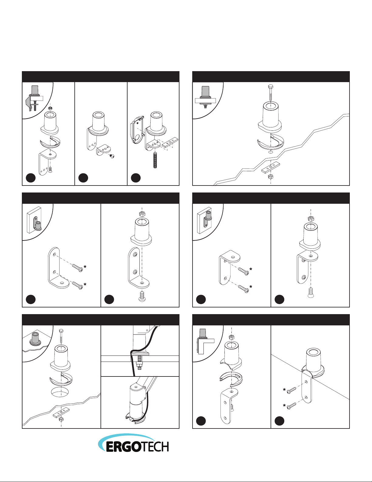
Mounting Instructions
Desk Clamp
I
A
D
G
C
B
E
H
F
L
Thru-Desk
1 2 3
Wall Mount Reverse Wall Mount
I
A
D
D
K
A
B
F
I
I
A
1 2 1 2
Hardware not in cluded.
*
J
Hardware not in cluded.
*
Grommet Hole Side Bolt
K
A
B
F
I
www.ergotechgroup.com
© 2017 Ergotech Group, LLC
D
1 2
INNOVATIVE ERGONOMIC SOLUTION
I
A
B
G
G
Hardware not in cluded.
*
PAGE 3 OF 5
Page 4
S
®
7FLEX
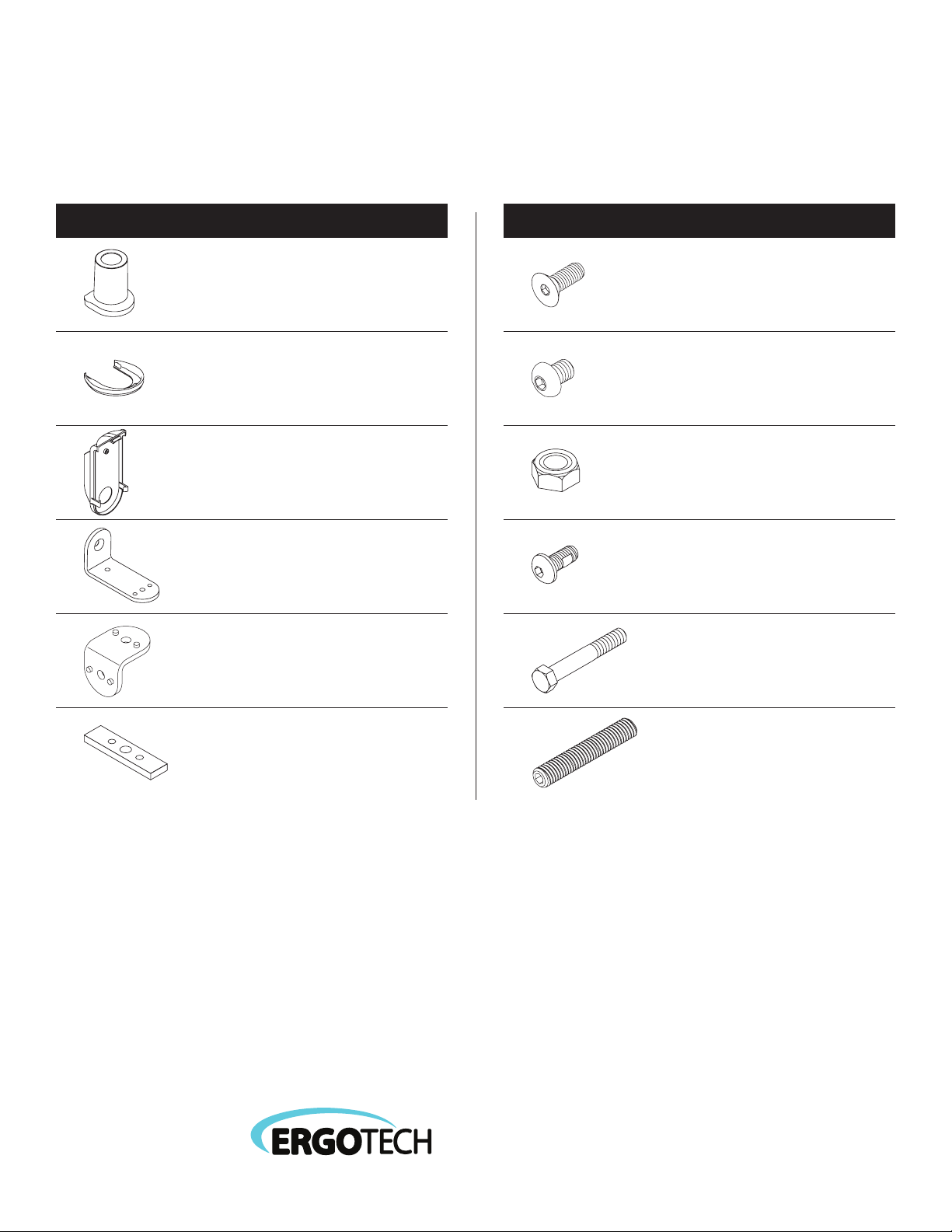
Mounting Part List
ITEM DESCRIPTION / PART NO. QUANTITY ITEM DESCRIPTION / PART NO. QUANTITY
A Mount Cup 1
40671 5
B Mount Cup Rubber Sole 1
105553
C Cable Management 1
105538
D Large “L” Brac ke t 1
701117
E Small “L” Bracket 1
111728
G 3/8-16 x 1" Flat Socket Cap Screw 1
701124
H 3/8-16 x 1/2" BHSCS 1
702898
I 3/8-16 Nylon Stop Nut 1
701418
J
701122
K 3/8-16 x 2-1/2" Hex Head Bolt 1
700268
3/8-16 x 7/8" Buon Socket Cap Screw
1
F Rectangular Spacer 1
701544
www.ergotechgroup.com
© 2017 Ergotech Group, LLC
INNOVATIVE ERGONOMIC SOLUTION
L 1/2-13 x 3" Socket Set Screw 1
701126
PAGE 4 OF 5
Page 5
S
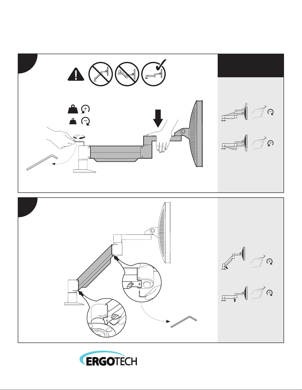
How do I counterbalance my arm?
IMPORTANT!
1
• Monitor must be on arm
• Arm must be in mount
Press the arm dow n to
approximately parallel with the
desk prior to turning the strength
adjustment screw.
If the arm drif ts upward,
turn the adjustment screw clockwise.
If the arm drifts downward ,
turn the adjustment screw counterclockwise.
7/32" Allen Wrench
2
Depending on the weight of your
monitor, you may have to make
15 -20 t urn s.
In some instances, further
counterbalance adjustments
are needed to allow the arm’s
instant height adjustment
function to work properly.
If your arm is not staying in
position after performing step 1,
follow these steps:
B
With arm in raised position,
tighten set screw (A).
A
With arm in horizontal position,
tighten set screw (B).
www.ergotechgroup.com
© 2017 Ergotech Group, LLC
Do not over tighten scre ws.
3/32" Allen Wrench
PAGE 5 OF 5
INNOVATIVE ERGONOMIC SOLUTION
 Loading...