

Operation Manual
ergometrics er900L
Art-Nr: 475.043 ! Version: 12/01B

Operation Manual for Ergometer er900L
Printed in Germany.
We reserve the right of modifications due to technical development at any time and without prior notice.
Reprinting, translation and copying in any form - also in parts - is only permitted after prior written consent
by the manufacturer.
This Operation Manual is not registered for automatic update in case of eventual alterations.
Information regarding the latest version is available from the manufacturer.
This Operation Manual Ergometer ergometrics 900L
Version: 12/01 B
is valid for following Software-Versions:
V.236, V.240 and V.243
ergoline GmbH
Lindenstraße 5
D-72475 Bitz
Tel.: +49 7431 98 94 - 0
Fax: +49 7431 98 94 - 127
e-mail: info@ergoline.com
internet: http://www.ergoline.com
Version: 12/01 Operation Manual er900L
Art-Nr: 475.043

Version: 12/01 Operation Manual er900L
Art-Nr: 475.043

Operation Manual
Contents
Ergometer
Type er900L
Table of Contents
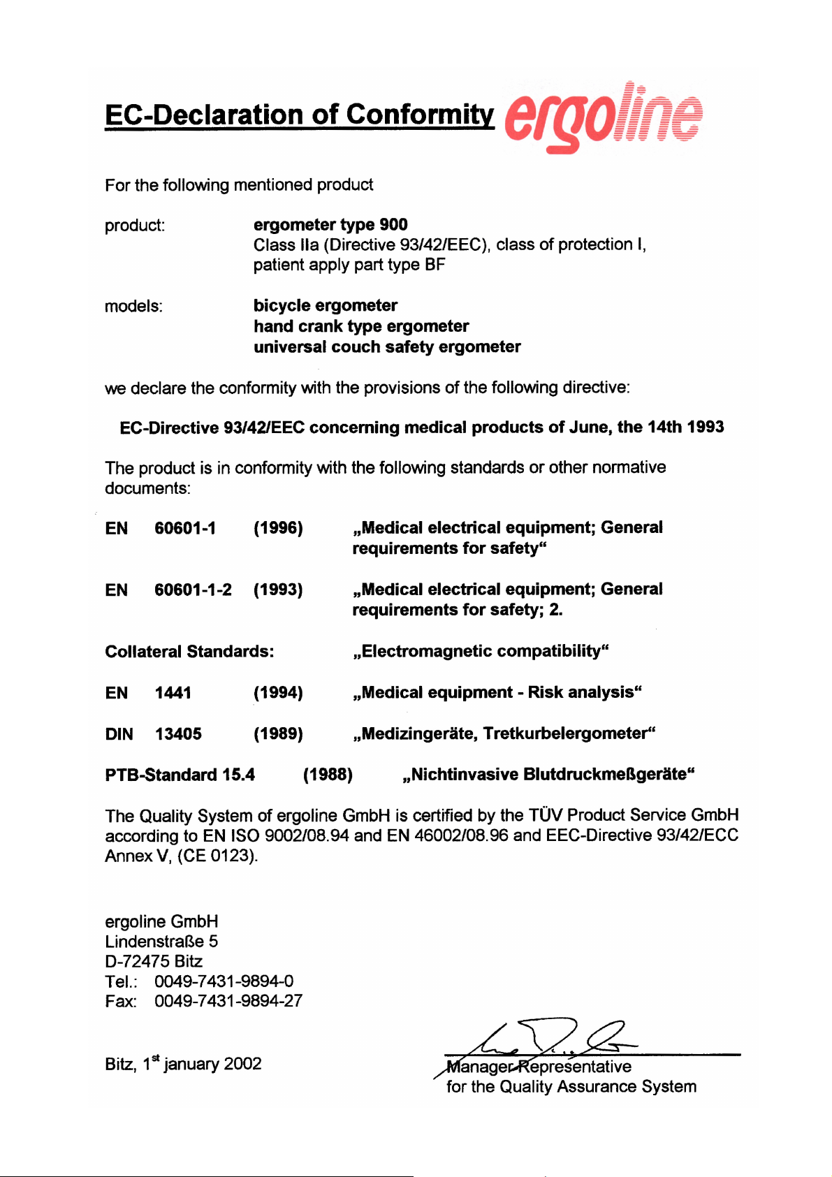
EC Declaration of Conformity
Table of Contents .............................................................................................. 1
Foreword ........................................................................................................... 4
1. Introduction ....................................................................................................... 5
1.1 Comments by the Manufacturer for the Operating Company ................................. 5
1.2 Product Relevant Regulations .............................................................................. 6
1.3 Warranty Regulation ............................................................................................ 6
2 Safety Notices ................................................................................................... 7
2.1 Safety .................................................................................................................. 7
2.2 Application as directed........................................................................................ 7
2.3 Fundamental Safety Comments ........................................................................... 7
2.4 Normative Notices ............................................................................................... 8
2.4.1 Notice for EMC (electromagnetic compatibility) ................................................... 8
2.5 Requirements for Operating Personnel ................................................................ 8
2.6 Safety and Device Protecting Features................................................................ 9
2.7 Measurement Accuracy Verification ..................................................................... 9
2.7.1 Routine Control of the Blood Pressure Measurement Unit .................................... 9
2.7.2 Periodic Accuracy Verification for Blood Pressure Unit ........................................ 9
2.7.3 Load Unit Inspection ............................................................................................ 9
2.8 Identification plate, Labelling.............................................................................. 10
3. Installation ....................................................................................................... 11
3.1 Installation steps ................................................................................................ 11
3.2 Scope of Delivery .............................................................................................. 11
3.3 Accessories ...................................................................................................... 12
3.4 Transport ........................................................................................................... 12
4 Putting into Operation .................................................................................... 13
4.1 Operating elements and Connections ................................................................ 13
4.2 Measurement head............................................................................................ 14
4.2.1 Keyboard .......................................................................................................... 14
4.3 Connectors and Interfaces ................................................................................. 15
4.3.1 Power Connection ............................................................................................. 15
4.3.2 Connector for Blood Pressure Cuff .................................................................... 15
4.3.3 Signal Connections ........................................................................................... 16
4.4 Power on Sequence .......................................................................................... 17
Version: 12/01
1
er900L Operation Manual
Art-Nr: 475.043

Ergometer
Type er900L
Operation Manual
Contents
5 Operation ......................................................................................................... 18
5.1 The Computer - Your Helper............................................................................... 18
5.2 The Display Unit ................................................................................................ 19
5.2.2 Displayed Parameters and their Meanings ........................................................ 19
5.3 The Printer ........................................................................................................ 20
5.3.1 Configuration of Printer ...................................................................................... 20
5.3.2 Printed Parameters ........................................................................................... 20
6 Ergometry Process......................................................................................... 21
6.1 General Preparations ........................................................................................ 21
6.1.1 Preparing the Patient......................................................................................... 21
6.1.2 Preparation for ECG Acquisition ....................................................................... 22
6.2 Preparation of the Ergometer (ECG Type P1 or P2) ......................................... 23
6.2.1 Basic Preparations for all Programs .................................................................. 23
6.2.2 Entries Peculiar to the use of Program 0 ............................................................ 24
6.2.3 Entries Peculiar to the use of Program 9 ............................................................ 24
6.3 Preparations for control by ECG or PC .............................................................. 25
6.4 Starting the Ergometry ....................................................................................... 25
6.4.1 Starting Ergometry with Internal Control.............................................................. 25
6.4.2 Starting an ECG or PC Controlled Ergometry .................................................... 25
6.5 Flowchart for complete Ergometry Process ....................................................... 26
6.6 Ergometric Protocol .......................................................................................... 29
6.7 Manual Control of Ergometry session ................................................................ 30
7 Configuration .................................................................................................. 31
7.1 General ............................................................................................................. 31
7.2 Call-up of the Monitor Program .......................................................................... 31
7.3 Base Settings....................................................................................................34
7.3.1 Date and Time................................................................................................... 34
7.3.2 Select Unit for Pressure Display ........................................................................ 35
7.3.3 ECG Start Pulse Duration (only for remote start of ECG).................................... 36
7.3.4 Select LANGUAGE ........................................................................................... 37
7.3.5 RPM Control ...................................................................................................... 38
7.3.6 Other Parameters .............................................................................................. 39
7.4 Defining an Ergometry Program ........................................................................ 40
7.4.1 Setup of Automatic Program 0 .......................................................................... 41
7.4.2 Definition of Programs 1-8................................................................................. 42
7.4.3 Definition of Program 9 for Pulse-Steady-State Training .................................... 44
er900L Operation Manual
Art-Nr: 475.043
2
Version: 12/01

Operation Manual
Contents
Ergometer
Type er900L
8 Structure of Programs .................................................................................... 46
8.1 General Structure of Programs 1-8 .................................................................... 46
8.1.1 Factory Settings ................................................................................................ 46
8.1.2 Creating Your Own Load Program ..................................................................... 47
8.2 Systematic Setup of Programs .......................................................................... 48
8.2.1 Setup of Automatic Load Program 0.................................................................. 48
8.2.2 Setup of the Fully Programmable Load Programs 1-8........................................ 52
8.2.3 Setup of Program 9, Steady-Pulse (Heart & Circulation Training) ....................... 54
9. Cleaning .......................................................................................................... 56
9.1 Cleaning the Unit ............................................................................................... 56
9.2 Cleaning the Blood Pressure Cuff ...................................................................... 56
Appendix A: Interfaces ................................................................................... 57
A.1 Input and Output Pin Specifications.................................................................... 57
Appendix B: Monitor Program ....................................................................... 70
B.1 Additional Settings in the Monitor Program ........................................................ 70
B.1.1 Setting the ECG Type ........................................................................................ 70
B.1.2 Setting the Baud Rate ....................................................................................... 71
B.1.2 Switching Between Internal and External Load Control ....................................... 72
B.1.4 Hardware Diagnostics .......................................................................................73
Appendix C: Program Listing ........................................................................ 74
Appendix D: Indicators .................................................................................. 74
D.1 PWC Values ...................................................................................................... 75
D.1.1 What is a PWC Value? ...................................................................................... 75
D.2 Training Indicator ............................................................................................... 76
Appendix E: HR Recording ........................................................................... 74
E.1. Heart Rate Feedback from ECG ....................................................................... 77
E.2. Pulse Monitor .................................................................................................... 77
Appendix E: Specification ............................................................................. 79
F.1: Technical Data ................................................................................................... 79
F.2: The Speed-correlated Capacity of Brake Power Control.................................... 80
Version: 12/01
3
er900L Operation Manual
Art-Nr: 475.043

Ergometer
Type er900L
Operation Manual
Foreword
Foreword:
We are pleased that you chose to purchase our computerized ergometer ergometrics er900L.
This is the appropriate decision for quality and performance in heart/circulation testing.
The computerized ergometer er900L has been specially designed with the medical and
ergonomic requirements in mind for quick and definitive stress analysis of the heart/circulation system. Computer control makes a fully automatic process of the entire spectrum of
ergometrics. Numerous programming options ensure that for every patient type there is an
applicable specific stress or training program ready at the touch of a button. Manually controlled stress analysis can also be carried out by the operator, independent of programs,
through manual entry of the load data. Programs in progress may also be interrupted to
control subsequent load steps by hand.
The built-in automatic blood pressure meter was especially designed for ergometrics. It
assures that systole, diastole and heart rate limits are continuously, automatically, monitored
even under stress condition. The computer controlled execution of all measurements and
analysis of results markedly simplifies the work of operating personnel. Accordingly, the
patient can be more closely observed and instructed. This allows the ergometric process to
be performed with the highest level of safety.
The display integrated into the console provides the operator continuously with current measurement data. The integrated printer provides continuous documentation of all measurements
resulting from the ergometric process.
This handbook is intended for operators of the unit. It explains all the functions of the ergometer in detail and in such a manner that operation of the unit can be learned through its use. It
can also be used as a reference.
We hope that you are successful in your work with the ergometrics er900L ergometer. We
always welcome your constructive remarks and improvement suggestions with regard to the
unit as well as to this handbook.
Your ergoline team
Attention !
This Operation Manual is a part of the unit in accordance with EN 60601-1:1990. It
should always be kept close to the unit. The necessary safety considerations, conforming to EC Guideline 93/42 EC are in chapter 2 of this manual.
Complying to the Safety Considerations is protecting against danger and risk for
life and limb, and prevents from improper application of the Ergometer.
Please comply with all sign of danger at the Ergometer. Replace lacking or damaged
sign immediately.
Familiarize yourself with the appropriate handling of the ergometer and all its control facilities prior to operating the equipment.
While being at work, it is too late !
Never allow that a person without the necessary expert knowledge is operating the
equipment.
er900L Operation Manual
Art-Nr: 475.043
4
Version: 12/01

Operation Manual
Introduction
Ergometer
Type er900L
1. Introduction
Within this Operation Manual, important comments to ensure the safety and to avoid
potential damage are labelled with following symbols:
Warning !
Describes a potential dangerous situation.
Failure to comply may lead to death or serious injuries, or may cause damage to the equipment or to the environment.
Important !
!
Application hints to achieve an optimal application of the device and further
helpful information.
This Operation Manual is an integral part of the device, and has to be available at the
equipment at any time.
This Operation Manual is designed by the manufacturer according to his best knowledge and experience in the construction, production and operation of the device.
The Operation Manual may be extended via special statements by the operating company, e.g. for supervision and obligatory registrations, internal maintenance plans, testing intervals.
1.1 Comments by the Manufacturer for the Operating Company
As operating company, you are responsible for :
- The professional and application as directed via expert personnel which has been
instructed into the correct operation of the equipment,
- Compliance to the safety relevant information and maintenance comments,
- Compliance to the safety regulations, safety comments as well as the precautions in
respect to vocational safety and accident prevention.
- The technical instruction of the operating personnel at the device and for having taken
notice of the Operation Manual.
- The Operation Manual is accessible for the operating personnel.
Following guidelines and regulations apply to the operation of the ergometer:
- EN 60601-1 (1996) „Medical electrical equipment; General requirements for
safety“
- EN 60601-1-2 (1993) „Medical electrical equipment; General requirements for
safety; 2.“
Version: 12/01
5
er900L Operation Manual
Art-Nr: 475.043

Ergometer
Type er900L
Operation Manual
Introduction
1.2 Product Relevant Regulations
- EC-Directive 93/42/EEC concerning medical products of June, the 14th 1993
- EC-Directive 89/336/EEC concerning „Electromagnetic compatibility“
1.3 Warranty Regulation
ergoline GmbH is only then, responsible for the safety and reliability of this
device when:
" all revisions, enhancements, repairs and service to the device are carried out by
ergoline authorized personnel, e.g. an ergoline dealer,
" ambient electrical service where the device is installed conform to IEC 601-1 and
" the device is operated in accordance with the Operation Manual.
er900L Operation Manual
Art-Nr: 475.043
6
Version: 12/01
Operation Manual
Safety Notices
Ergometer
Type er900L
2 Safety Notices
2.1 Safety
Complying to the safety comments protects from potential injuries and prevents improper application of the ergometer. Each operator of this ergometer as well as personnel which is in charge of installation, maintenance, examination or repair of this
ergometer, must have read and fully understood the contents of this Operation Manual
prior to operating or do any work on this device.
Special attention is required at sections labelled with additional symbols .
2.2 Application as directed
a) The supine ergometer er900L must only used for precise Cardio-Vascular tests un-
der resting and stress test conditions. With legrest attached (optional), the leaning
ergometer may also be used as couch for medical treatment
b) Application under outdoor conditions is not permitted.
c) In case the ergometer is not being used according to above conditions, and if be-
cause of that any injuries or serious impact on individuals, or if damage of property
is caused, then from this no liability of the manufacturer can be derived.
2.3 Fundamental Safety Comments
Note: We herewith notify that this manual is in accordance with regulations set forth by
the EC-Directive 93/42 EEC and the standards IEC601-1 (1996) and EN606011-2 (1993). These regulations are however, not contained within this handbook.
The ergometer must only be operated in perfect working order in technical respect.
Despite of the precautions, the operation of the ergometer may involve certain
risk or danger, especially if
- improper application or,
- application is not as directed
are the cause.
There is the hazard of injuries or of property damage, in case of Nonconformance to
the Operation Manual, especially to the S a fe t y N o t e s
Version: 12/01
7
er900L Operation Manual
Art-Nr: 475.043

Ergometer
Type er900L
It is necessary to ensure that no dangerous ground currents occur as a
result of attaching the ergometer to other devices. Device specifications
of the ergometrics er900L are in the appendix to this manual. Direct
your questions to your dealer or to ergoline’s service department. Especially at the coupling of several devices to a measurement system is
has to be taken care, that proper grounding is achieved via a single
power supply, e.g. wall socket.
The ergometrics er900L ergometer should only be operated where electrical requirements meet IEC 601-1.
This device is not suitable for use in rooms or areas where there is danger of explosion. .
Always observe accident prevention precautions when operating this
device.
Operation Manual
Safety Notices
In the event that the pressure in the blood pressure cuff is too high,
remove the cuff from the patient's arm immediately.
This unit may only be operated for therapy or diagnosis purposes under
!
the supervision of qualified personal.
2.4 Normative Notices
2.4.1 Notice for EMC (electromagnetic compatibility)
- The EMC test was done with a interference level of 3V/m. The device should not be
used in areas with a higher level.
- The device should not be used beside a high voltage system.
- To connect the device with other devices it's only allowed to use special shielded
cable provided by ergoline.
- Strong transmitting equipment may not be operated in the immediate vicinity of this
device..
- Electromagnetic interferences will appear first by a instable value of load in the display. If the value will change without reason while the speed is >30 1/min. It may be
that this is caused by an electromagnetic interference.
2.5 Requirements for Operating Personnel
The operating personnel of this ergometer have to be :
- properly instructed and trained regarding the operation of the ergometer,
- have to have full command regarding the handling of the device,
- have to aware of the applicable relevant safety requirements for the operation of
such devices, and act accordingly (see Chap. „Introduction“),
- have to be informed regarding additional regulations, e.g. safety regulations,
- have to be informed regarding potential hazard and risk arising from the operation of
such devices.
er900L Operation Manual
Art-Nr: 475.043
8
Version: 12/01

Operation Manual
Safety Notices
Ergometer
Type er900L
2.6 Safety and Device Protecting Features
The device is equipped with following safety and device protecting features :
- High current protection which prevents damage to the device and potential danger to
person, e.g. in case of short circuit.
2.7 Measurement Accuracy Verification
Maintenance: The ergometrics 900L ergometer must be regularly inspected and main-
tained, in time intervals of two years, in accordance with lawful regulations. Alterations
to the ergometer’s measurement capabilities are cause for re-certification.
2.7.1 Routine Control of the Blood Pressure Measurement Unit
The automatic blood pressure measurement unit in the console of the ergometer must
be approved and recalibrated every two years by personnel authorized by ergoline.
2.7.2 Periodic Accuracy Verification for Blood Pressure Unit
EC-Directive 93/42/EEC operator regulations stipulate that the automatic blood pressure unit in the ergometer´s console must undergo a routine technical inspection every
two years. (see page II in this operators Manual)
2.7.3 Load Unit Inspection
EC-Directive 93/42/EEC operator regulations requires qualified technical maintenance
of the load unit at two years intervals. This is to be performed by an ergoline authorized
service technician.
Version: 12/01
9
er900L Operation Manual
Art-Nr: 475.043
Ergometer
Type er900L
Operation Manual
Safety Notices
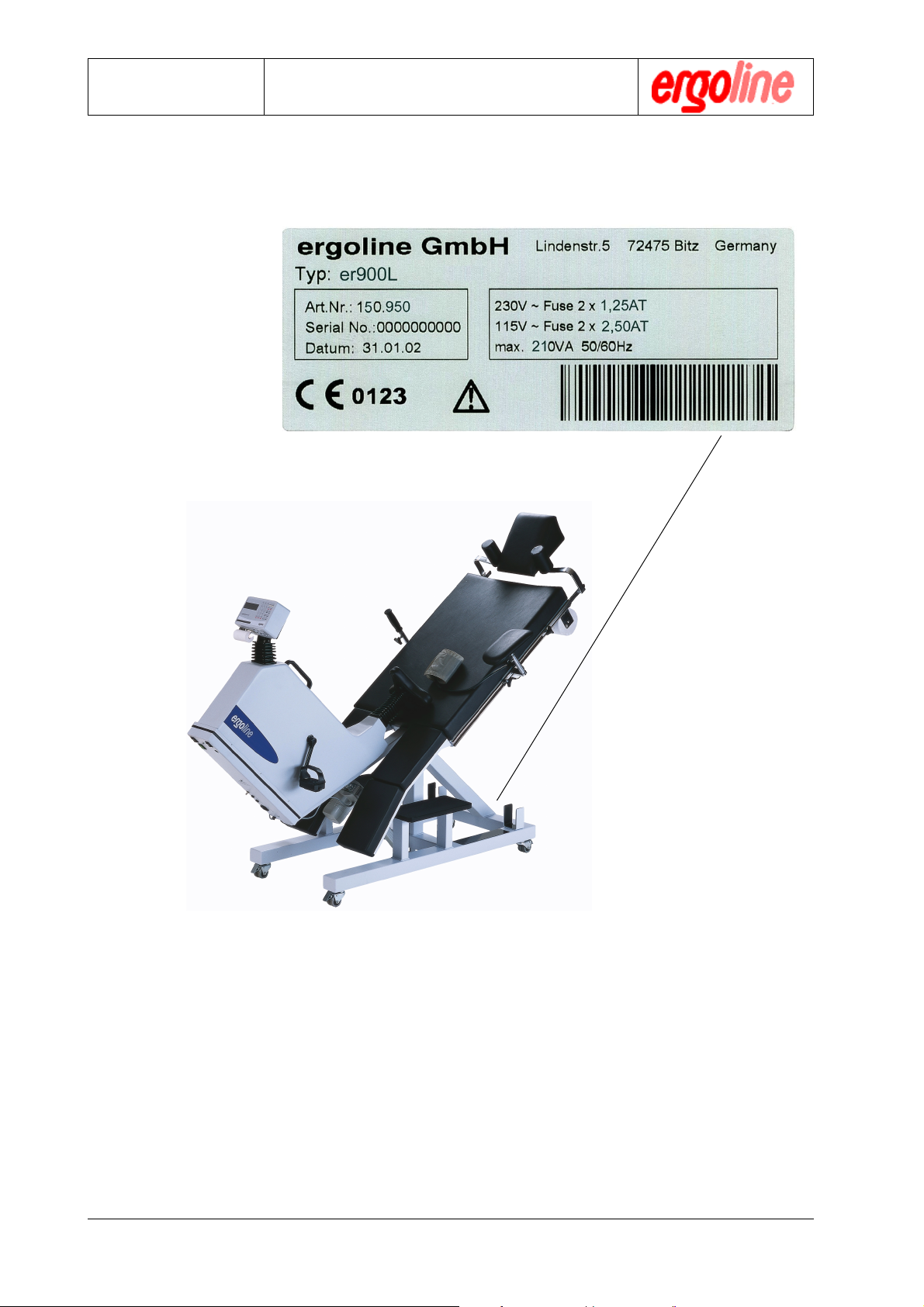
2.8 Identification plate, Labelling
er900L Operation Manual
Art-Nr: 475.043
10
label with serial number
Version: 12/01
Operation Manual
Installation
Ergometer
Type er900L
3. Installation
This section describes the required installation steps in order to establish operational
readiness. The steps described are also required at initial installation after delivery of
the device.
3.1 Installation steps
1) Mount the locking castors.
2) Fix paper roll holder and fix crepe paper roll.
3) Mount arm support on the left hand side.
4) Fix the right running board on the support intended for via screws supplied.
5 )Connect blood pressure cuff according to 4.3.2 at the measurement head.
6) Connect mains cable according to 4.3.1 at the power inlet.
3.2 Scope of Delivery
The standard scope of delivery consists of :
1 blood pressure cuff
2 locking castors.
3 thermal paper for printer (2 rolls)
4 Measurement head with rear cover
5 arm support, left
6 running board, left + right (not visible)
7 head support
not in picture:
paper roll holder
crepe paper roll.
mains cable, 5 m
Final test protocol
348 1 7
5
6
Operation Manual
optional :
8 Handle, right with mounting right
9 legrest (left + right)
connecting cable to ECG (not in picture)
Version: 12/01
11
9
2
er900L Operation Manual
Art-Nr: 475.043

Ergometer
Type er900L
3.3 Accessories
Order No. Description
100.948 Thermal paper roll (1 Set = 10 pieces)
200.194 Cuff for ergometry, adults
200.199 Cuff for ergometry, adults (connecting hose 2 m)
200.230 Cuff for ergometry, long version for strong arms
200.231 Cuff for ergometry, special (strong arms/connecting hose2 m)
200.200 Cuff for ergometry, children
313.420.9 Polar Receiver er900
424.016 Polar chest belt
200.205 2. arm rest with support (right)
200.206 Handle, right with mounting right
200.209 leg rest attachable, left + right (only for couch width 60 cm)
200.207 Swivelling arrest out of stainless steel (dimensions 450 x 300 mm)
200.210 Infusion holder
300.940 pedal shoes right + left complete
480.016 crepe paper roll
Operation Manual
Installation
475.043 er900L Operation Manual, English Version
475.190 er900 Service Manual, English Version
3.4 Transport
Please ensure that the mains cable is removed prior to transporting the device.
!!
!
!!
After releasing the locking casters, the ergometer er900L may be easily moved to the
working space within the room.
er900L Operation Manual
Art-Nr: 475.043
12
Version: 12/01
Operation Manual
Putting into Operation
Ergometer
Type er900L
4 Putting into Operation
Check the mains fuse at the respective workstation prior to putting into operation the
device. Minimal fuse value: 16A.
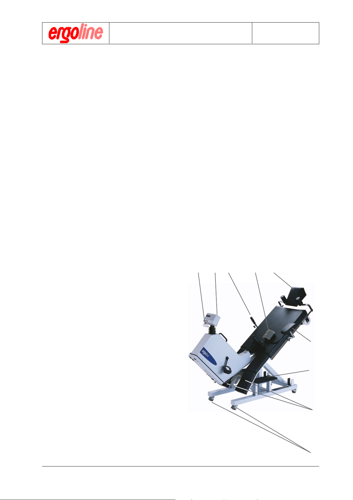
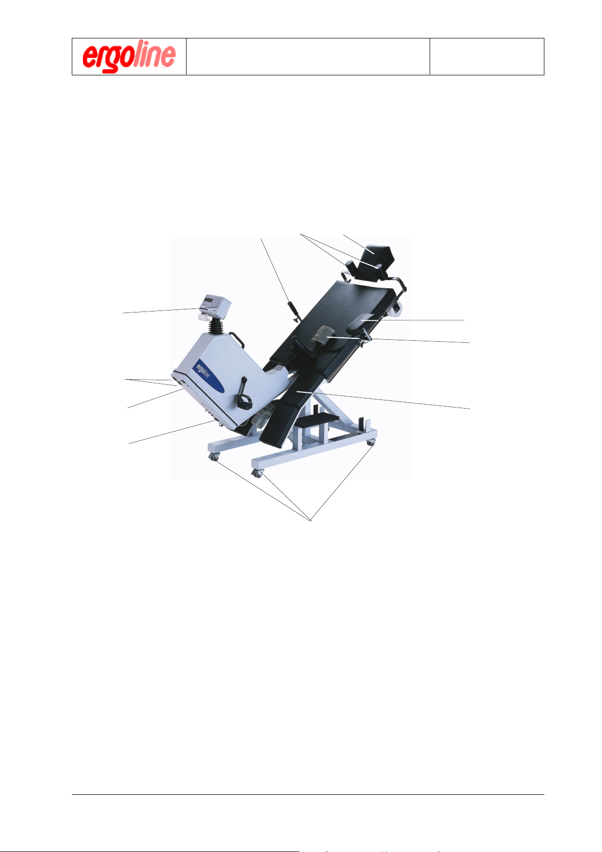
4.1 Operating elements and Connections
54 6
8
2
3
1
7
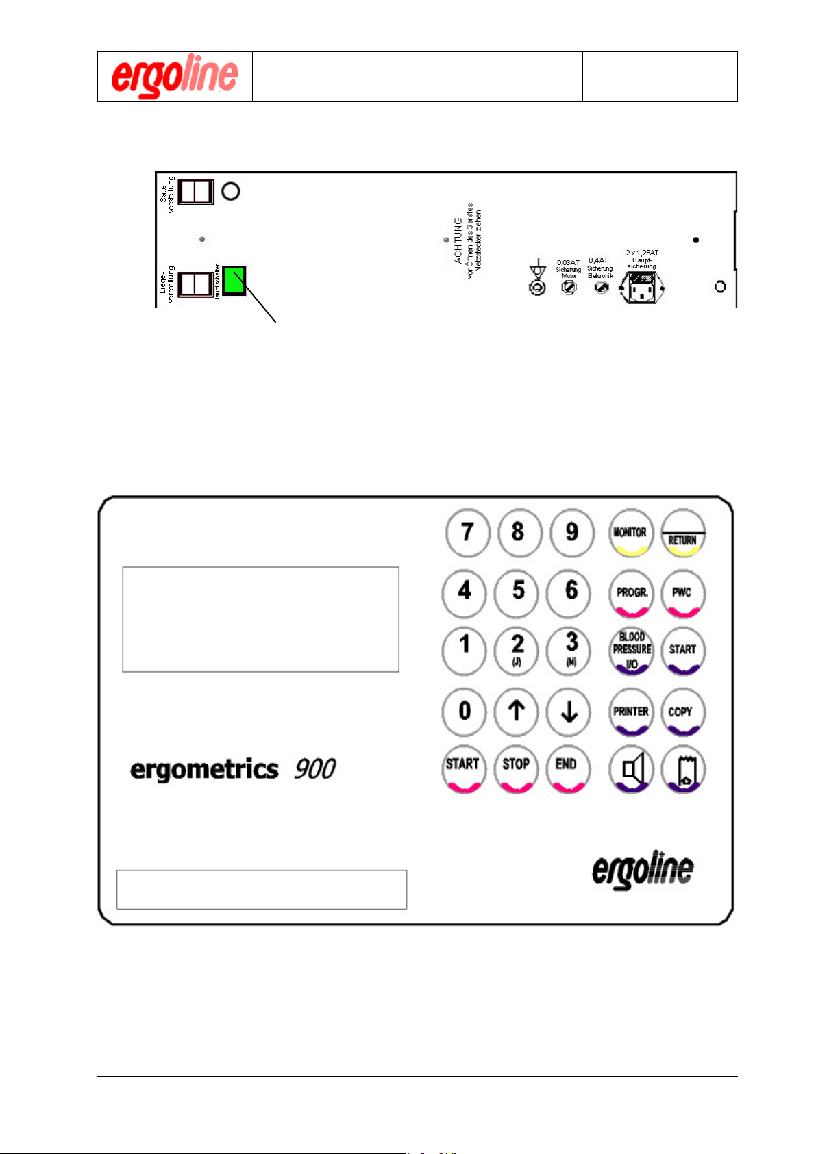
1 Power connector, fuse and main power switch
2 Couch and seat adjustment
3 Mains power switch
10
9
11
4 Shoulder support
5 Handle with mounting for patient
6 Head support
7 Locking castors
8 Measurement head with keypad, display and printer
9 Blood pressure cuff , connection to the left or right at choice
10 Arm rest for blood pressure measurement
11 leg erst left + right, attachle (optional)
Version: 12/01
13
er900L Operation Manual
Art-Nr: 475.043
Ergometer
Type er900L
Putting into Operation
4.2 Measurement head
Operation Manual
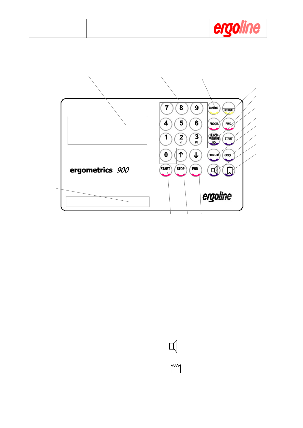
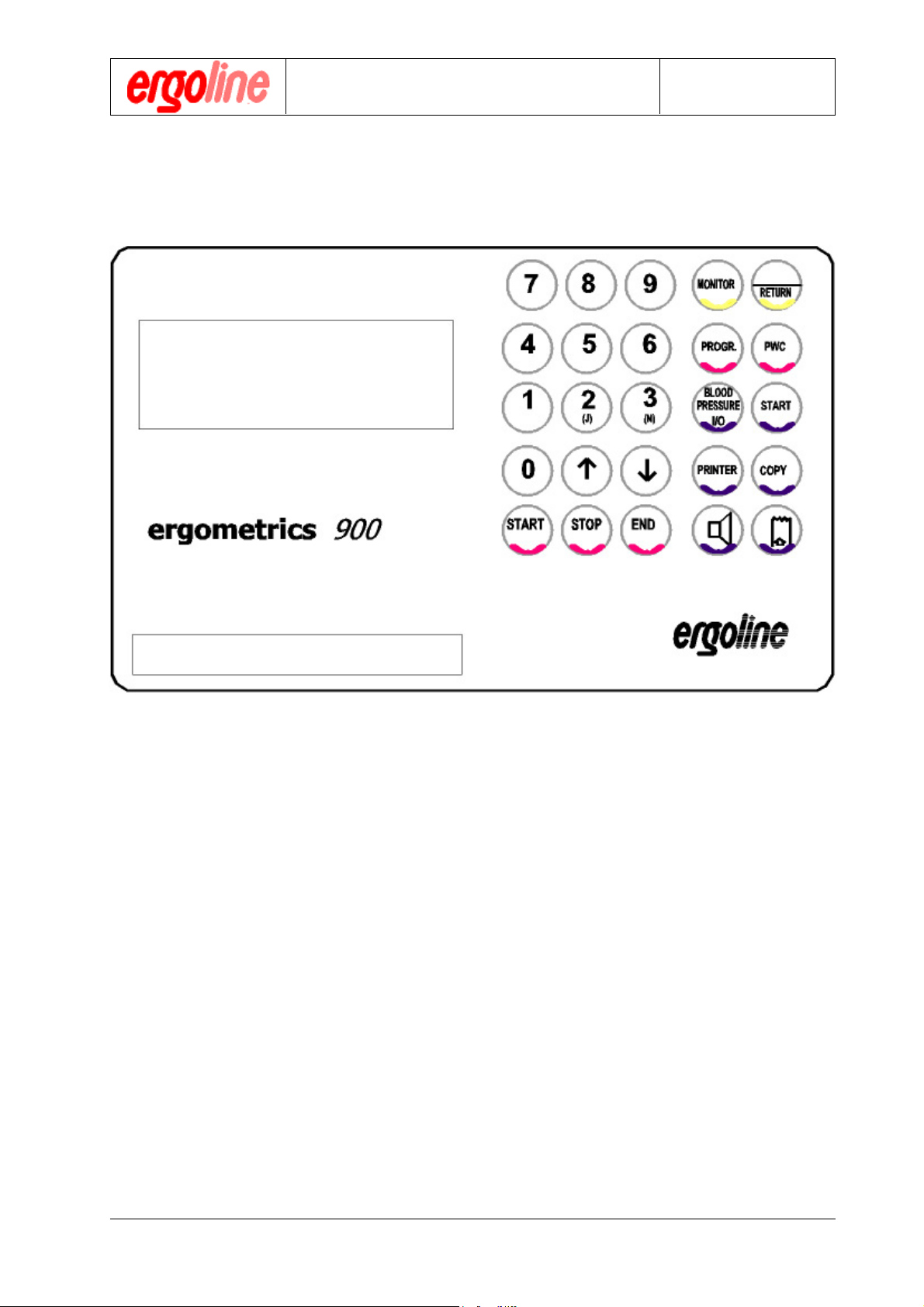
4.2.1 Keyboard
2
1378
9
10
11
12
13
14
15
16
1 LCD-Display
2 Paper Ejection Slot
3 Numeric Keypad
4 START to start the ergometric
process
5 STOP for interrupting the load
increments
6 END to stop the ergometric
process
7 MONITOR to call up the monitor pro-
gram: to program ergometer, test routines, adjustments, and assign stan-
dard settings
8 RETURN to confirm and store entries
9 PROGR. key to call up, and make
temporary modifications to,
ergometric programs
10 PWC to call up definable PWC
values subsequent to an
ergometric process
456
11 BLOOD PRESS. I/0 to initiate or stop blood
pressure measurement ( at
anytime possible)
12 START to manually initiate a blood
pressure measurement, can
be done anytime when the
blood pressure is enabled
13 Printer switches printer output (inter-
nal, external or turned off)
14 Copy produces a copy of the re-
sult protocol
15 Toggle QRS beep on/off
16 Printer paper feed
er900L Operation Manual
Art-Nr: 475.043
14
Version: 12/01
Operation Manual
Putting into Operation
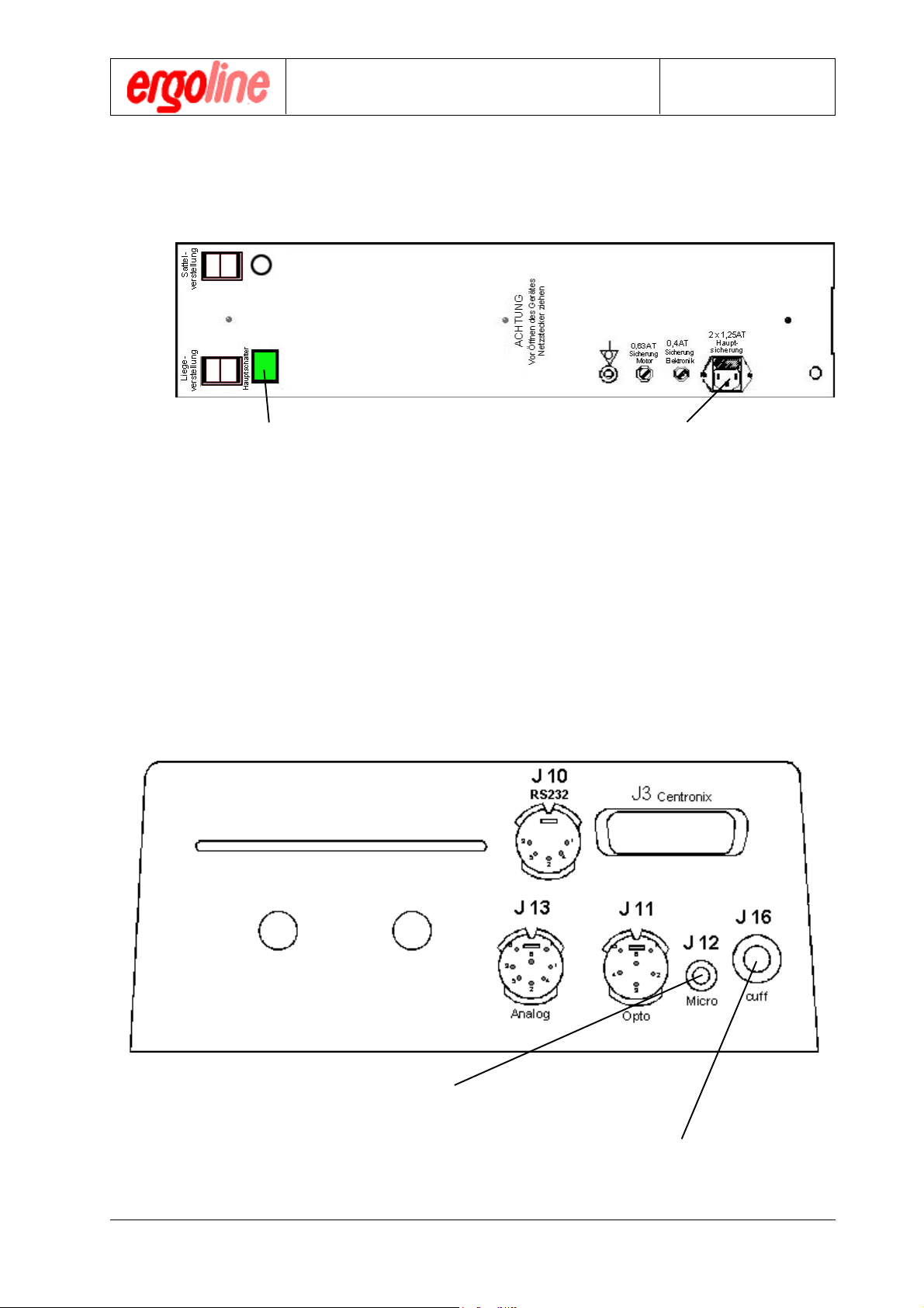
4.3 Connectors and Interfaces
4.3.1 Power Connection
Ergometer
Type er900L
1) Make sure that the unit power switch is in
the off position (not depressed).
When using an ergoline utility cart with suction device, connect the unit’s power
!
4.3.2 Connector for Blood Pressure Cuff
plug to one of the white outlets on the utility cart. The ergometer can then be switched
on and off together with the suction device.
2) Connect the unit’s power plug via the supplied mains cable to power outlet with same
voltage as indicated at the indication label
Version: 12/01
The microphone cable is to be
connected via RCA-Jack to J12
15
The cuff tube is to be connected
via Luer-Lok to J16 with the measure-
ment head .
er900L Operation Manual
Art-Nr: 475.043
Ergometer
Type er900L
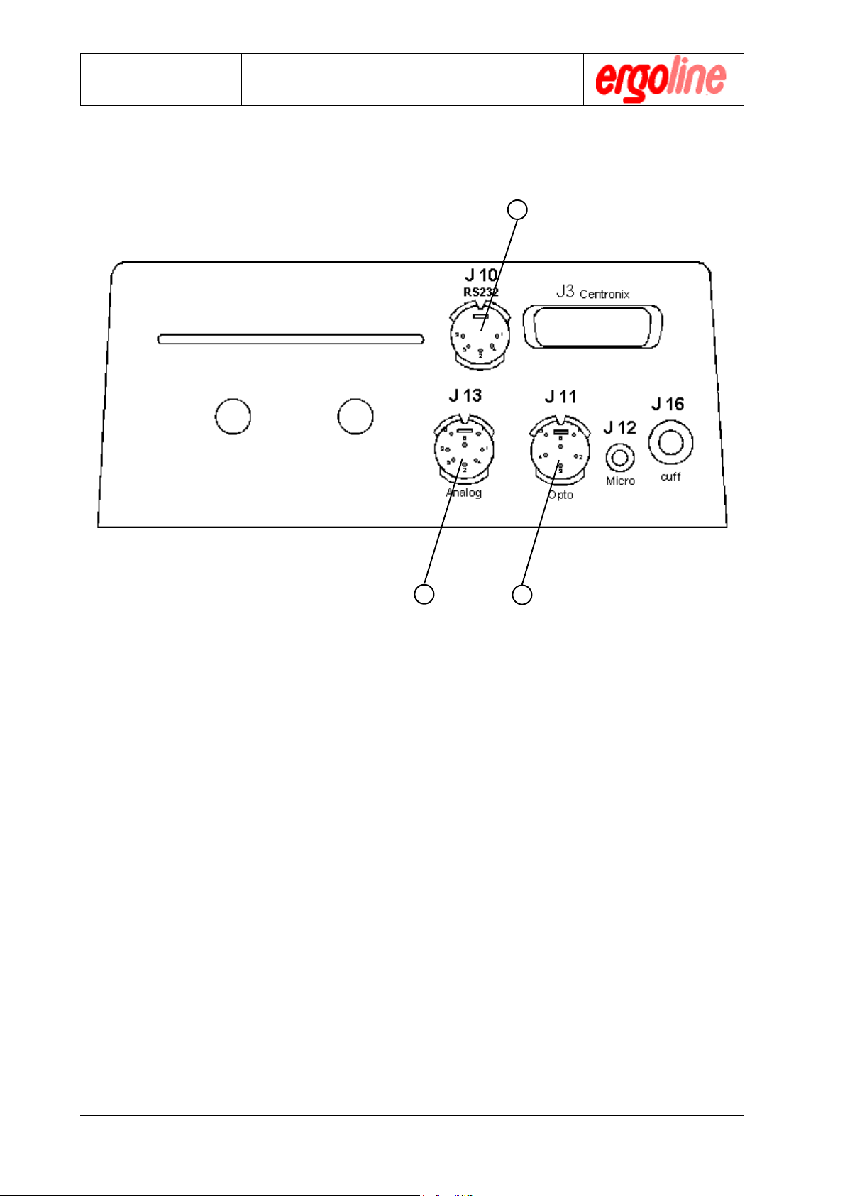
4.3.3 Signal Connections
Operation Manual
Putting into Operation
1
23
1) Digital RS-232 interface connector for PC or ECG
2) Analog interface for analog control and analog data transfer to ECG.
3) Fiber-optic connector for ear/finger clip or HR input from and ECG
The interface pin configuration as well as related technical data are in the
!
appendix of this Operation Manual.
er900L Operation Manual
Art-Nr: 475.043
16
Version: 12/01
Operation Manual
Putting into Operation
Ergometer
Type er900L
4.4 Power on Sequence
Mains power switch
The unit will subsequently execute a self-test. At the end of the self-test the main menu
will appear as below:
P = 000 W r = 000 /min.
HF= 000 /min. t = 00 min.
S = 000 mmHg D = 000 mmHg
PROG 0 BP OFF PR. INT
Version: 12/01
17
er900L Operation Manual
Art-Nr: 475.043
Ergometer
Type er900L
Operation Manual
Operation
5 Operation
5.1 The Computer - Your Helper
The half-leaning/leaning ergometer er900L was designed so that ergometric processes
could be conducted
simply - quickly - exactly - safely.
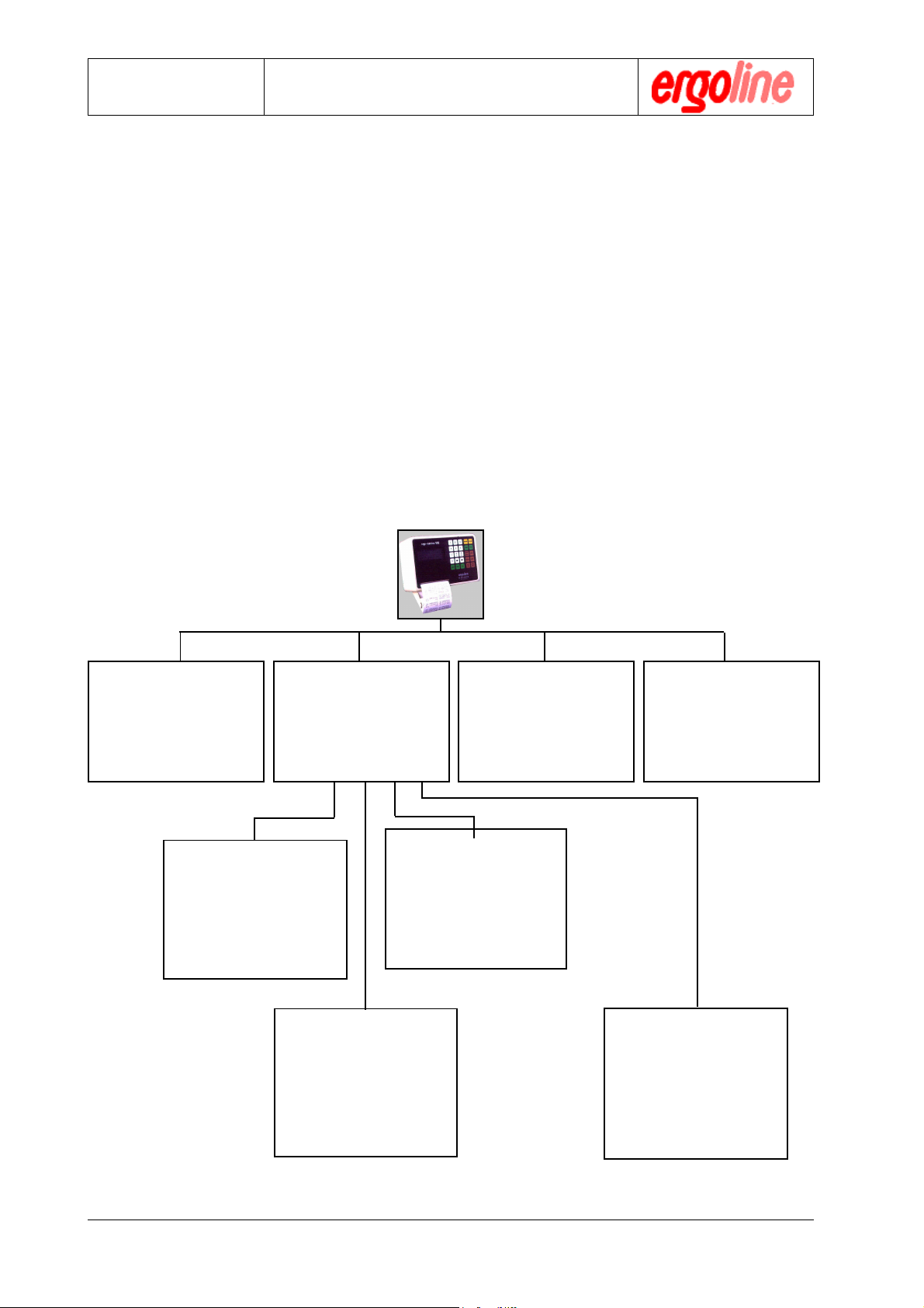
In order to achieve this, the computer is an indispensable aid. The integrated and especially designed blood pressure module for the ergometric process, makes computer
monitoring of the patient and his blood pressure condition largely autonomous. The
schematics below demonstrate the versatility of the unit .
Automatic Load
Program No. 0
Load program for patients whose
circulatory condition is not clear.
The ergometer tests the condition
of the patient’s circulatory system, and then selects an optimal
load program for the stress test.
With Circulation
Monitoring
Blood pressure and heart rate are
sampled and documented at the preset time interval. Heart rate and blood
pressure are simultaneously monitored for alarm limits and, if necessary, cause an alarm and abort the
load program.
Load Programs
No. 1 through 8
These load programs can be defined by the operator. Selection of
up to 12 load increments is possible. Blood pressure measurement
interval and parameter monitoring
are fully selectable.
Without Circulation
Monitoring
Blood pressure module is off. The
circulation condition is not monitored
and exceeding alarm limits do not
cause an alarm.
Manual Intervention
The preset program can be interrupted
at any time and the load levels may
be manually altered. When circulation conditions are being monitored
only load increments are interrupted.
Circulation data will continue to be
sampled, documented and checked
against alarm limit values in the preset time interval.
Load Program No. 9
Pulse-Steady-State
Special program for pulse-steadystate-training. A selected heart
rate will be maintained stable over
the entire training period.
Experimental Program
Prior to starting the program, each
program may be altered for this specific ergometry. These alterations are
not stored, and the standard settings
are restored after this ergometry.
Such sessions can also be manually
controlled and run with, or without,
circulation monitoring.
Use of the Blood
Pressure Module
without Load
er900L Operation Manual
Art-Nr: 475.043
18
Version: 12/01
Operation Manual
Operation
5.2 The Display Unit
5.2.2 Displayed Parameters and their Meanings
P = 000 W r = 000 /min.
HF= 000 /min. t = 00 min.
S = 000 mmHg D = 000 mmHg
PROG 0 BP OFF PR. INT
Ergometer
Type er900L
P = 000 W = current load in Watts (Po= initial load,
P
=maximum load)
max
r = 000 /min = current revolutions per minute
HR = 000 /min = heart rate at the time of the last blood pressure reading
(current heart rate in case of continuous HR-signal )
t = 00 min = duration of the ergometry in min
S = 000 mmHg = systolic value of the last blood pressure reading (the mea-
surement may be displayed either in mmHg or kPa)
D = 000 mmHg = diastolic value of the last blood pressure reading (the
measurement may be displayed either in mmHg or kPa)
PROG 0 = program selected (No. 0...9)
BP OFF = status of the blood pressure measurement (on or off)
PR. INT = status of the printer driver (Intern, Extern or Off)
Wt. = weight of the test subject
INT = interval of the blood pressure measurements in minutes
Version: 12/01
19
er900L Operation Manual
Art-Nr: 475.043
Ergometer
Type er900L
Operation Manual
Operation
5.3 The Printer
5.3.1 Configuration of Printer
The printer may be configured in any one of three modes. This is done by pressing the
brown key „Printer“ (13). The status of the printer can be read from the lower right
corner of the display. The various configurations have the following meaning:
INT = The integrated system printer is enabled and prints all displayed parameters
immediately after each load change and/or blood pressure measurement.
EXT = The integrated printer is disabled. All data are exported to another system (ECG,
PC or external printer) and printed there.
OFF = The printer is turned off. (This setting is only valid for the current stress test and
will revert to „INT“ as soon as the current stress test is terminated.)
5.3.2 Printed Parameters
The printer documents all parameters that are shown in the display. Printing will occur
immediately following each load change and/or blood pressure measurement. Printing
will also occur after the recovery period when the ergometry is aborted or comes to a
programmed termination. There are three parts of the ergometric protocol:
2. Recovery Protocol:
Documents each blood pressure measurement during the recovery phase.
1. Loading Protocol:
Documents the blood pressure reading
at rest , at each load increment and after each blood pressure measurement
during the load phase and the elapsed
time at termination.
er900L Operation Manual
Art-Nr: 475.043
3. Summary Protocol:
A summary of the ergometry with the PWC
values at the end of the total ergometry.
20
Version: 12/01

Operation Manual
Ergometry process
Ergometer
Type er900L
6. Ergometry Process
6.1 General Preparations
6.1.1 Preparing the Patient
As support for getting on or off the ergometer, the patient may only use hand
grip (A). The arm rest (D) and the hand grip (C) must not be used as support
for getting on/off the ergometer and must not be strained with the whole body
weight.
1) Place the backrest of the ergometer at a 45 degree angle so that the patient may
comfortably take his place.
2) Position the shoulder and headrests (C) such that they are outside the backrest area.
3) If there are leg rests (B), remove them, or at least the one on the side that the patient
will step up on.
4) Have the patient take his place on ergometer and put his feet on pedals.
5) Put the patient in the optimal position, such that his outstretched leg makes an angle
of 170 degrees between upper body and upper leg. Fix this position by adjusting the
saddle.
6) Now move the shoulder and headrests (C) such that the shoulder supports lightly
touch the shoulders.
C
hand grip
head rest
shoulder rest
locking
screws
A
hand grip
for
patient
D
arm rest
locking
screws
B
leg
support
Version: 12/01
B
21
er900L Operation Manual
Art-Nr: 475.043
Ergometer
Type er900L
Operation Manual
Ergometry process
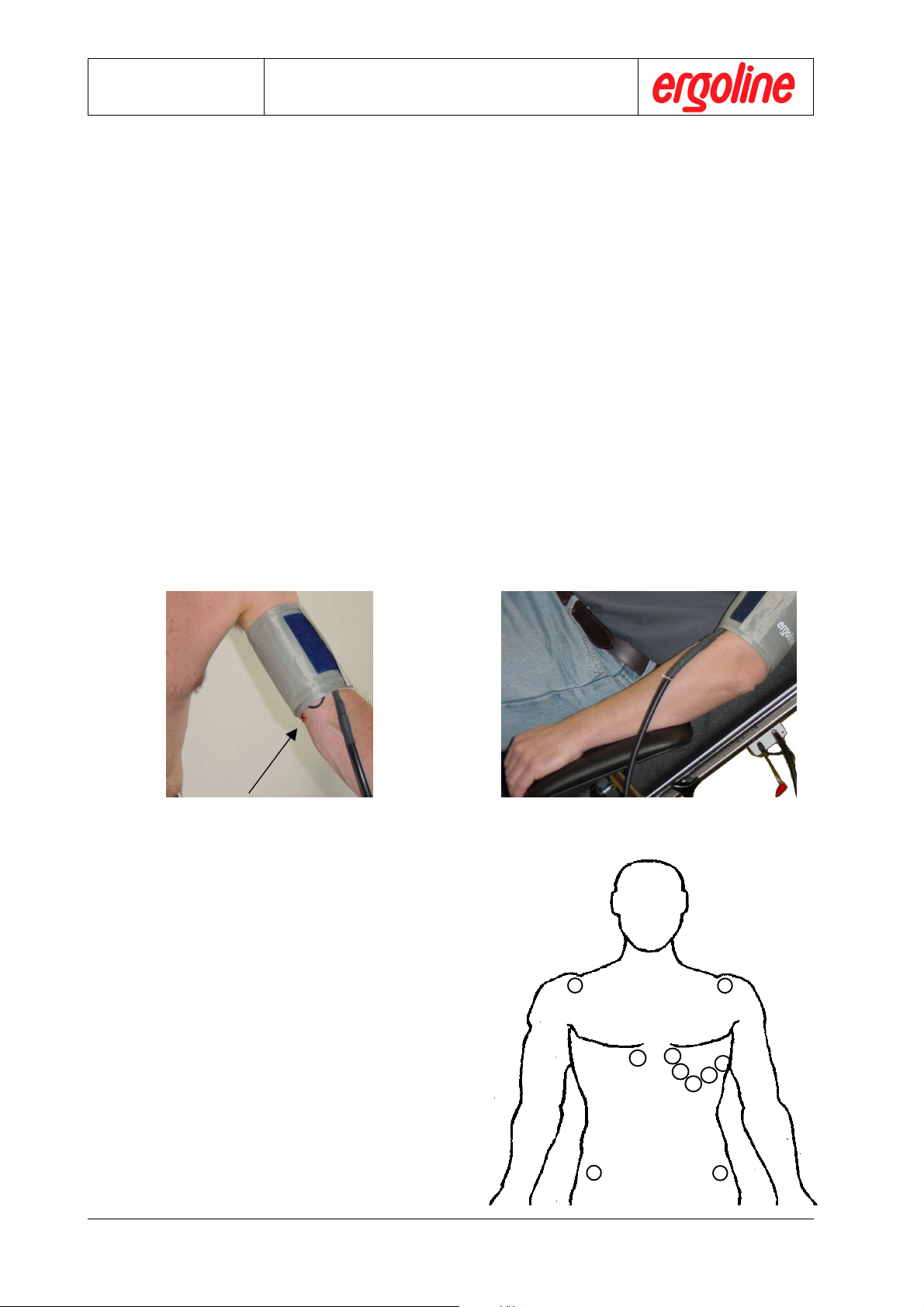
7. Applying the Blood Pressure cuff :
* Feel for the position of arteria brachialis and position microphone (identified by
the red tab) precisely above arteria brachialis (E).
* Apply the airless cuff tightly at upper arm in order to prevent slipping during the
ergometry test, however not extremely tight.
* Apply cuff directly on skin, i.e. you must not use an intermediate layer out of
cloth, paper, .....
* The cuff should not touch the elbow.
* After application of cuff, the patient shold use the arm rest (F) as support (and
reduce thereby movement artefacts)
* Check that the cuff tubing is unimpeded and will not knock against any objects
when the patient has placed his hand at the handlebars and starts pedalling.
Move the armrest (D) accordingly toward the head or toward the leg. The con-
necting tube for the cuff should be as free as possible and not crimped or pinched
in any way.
* Advise the patient to keep his arm as still as possible during an ongoing
blood pressure measurement, and especially to avoid extreme contraction
of muscles of the upper arm.
E
- Microphone precisely above arteria brachialis
- Microphone position identified by red tab (cross)
6.1.3 Preparation for ECG Acquisition
- Since in leaning/half-leaning ergometry
electrodes cannot be placed on the
patient’s back or extremities, position the
electrodes as shown in figure.
- Configure your ECG unit according to your
needs and proceed as described in this
manual in Chap. 7.4 „Ergometry Programing“ .
F
Application of BP cuff, er900L
RR
R
RR
C2
C1
C3
C4
C5
C6
LL
L
LL
er900L Operation Manual
Art-Nr: 475.043
22
NN
N
NN
FF
F
FF
Version: 12/01
B

Operation Manual
Ergometry process
6.2 Preparation of the Ergometer (ECG Type P1 or P2)
These preparation instructions are only applicable to usage of the ergom-
!
6.2.1 Basic Preparations for all Programs
eter in conjunction with interface modes ECG-Type P1 or P2, See Appendix A. The ergometer can only be controlled by its own program in these
modes.
1. Press the red colored key „PROG.“ and select the appropriate program for the pa-
tient with the numeric keypad.
Ergometer
Type er900L
#
2. Enter the patient’s weight. The ergometer needs this information to calculate exact
PWC values.
PROG x Wt. = xxx HR < xxx
S < xxx mmHg D < xxx mmHg
Po = xxx W Pmax = xxx W
INTERV.BPM = xx min.
3. When necessary, you can alter any parameter to create a special ergometric ses-
sion. These alterations will be lost as soon as the special session is ended. Thereafter the standard base values will again be in place in the program (see chapter 7.
„Configuration“.
!
Version: 12/01
Altered parameters, that are entered prior to program start are lost after
the end of the ergometric session.
23
er900L Operation Manual
Art-Nr: 475.043

Ergometer
Type er900L
6.2.2 Entries Peculiar to the use of Program 0
When using program 0, the maximum heart rate (HR) should always be entered specific to the individual patient. Since this value serves as the target frequency for loading, it must be specifically adapted to the age and health of the patient. The remaining
parameters, in particular the alarm parameter, should be established in the configuration so that even the weak patient can withstand the ergometric session without danger.
Here also, all other parameters may be altered for a specific ergometric session.
Always enter the maximum heart rate (HR) for program 0 specific to the
!
6.2.3 Entries Peculiar to the use of Program 9
age and strength of the patient. When possible, provide the ergometer
with a continuous heart rate by using an ear/finger clip, a pulse monitor or
the HR feedback from an ECG
Operation Manual
Ergometry process
Patient specific maximum heart rate (HR) should also be entered for program 9 to
reflect the patient’s training requirements.
Only use program 9 when a continuous heart rate source is used. That is,
!
when an ear/finger clip, a pulse monitor or a HR feedback from an ECG is
connected.
er900L Operation Manual
Art-Nr: 475.043
24
Version: 12/01

Operation Manual
Ergometry process
6.3 Preparations for control by ECG or PC
The ergometer must be specifically configured to the controlling ECG-Type or PC, see
Appendix. The ECG or PC is then in total control of the ergometry. Any entries that may
have been made on the ergometer are therefore nullified. There is no preparation of
the ergometer to be made on the console. Configure your ECG or PC in accordance
with the appropriate operator’s instructions for ergometry. Start the ergometric session with the ECG or PC.
6.4 Starting the Ergometry
6.4.1 Starting Ergometry with Internal Control
1. Check to see if all the parameters are correctly entered.
2. Start the ergometric procedure by pressing the red colored „START“ key.
Ergometer
Type er900L
The ergometer will begin by measuring the quiescent value for blood pressure.
##
#
##
6.4.2 Starting an ECG or PC Controlled Ergometry
Start the ergometric program on your ECG or PC in accordance with the corresponding instructions. After a successful start the ergometer will begin by measuring the quiescent value for blood pressure.
Version: 12/01
25
er900L Operation Manual
Art-Nr: 475.043

Ergometer
Operation Manual
Type er900L
6.5 Flowchart for complete Ergometry Process
This ergometric process flow description is only valid for use of the ergom-
!
Legend:
eter under internal control. When control is exercised by an ECG or PC
refer to the documentation for those devices.
= input via operating
personell
Selection of specific ergometric program
Assign patient to patient group, and select program for this patient accordingly, or select the
automatic program 0 for patients who you cannot be classified, or select program 9 for
patients who are to undergo heart-steady-state-training.
.
Possible modification of parameters
Prior to beginning an ergometric session you may alter any parameter for this specific ergometry.
Start of Ergometry
Press the red coloured „START“ key to begin the ergometric session.
Quiescent blood pressure measurement
Immediately after starting the ergometer, the quiescent blood pressure measurement will be
taken. It is important that the patient remains absolutely calm during this measurement as the
filter parameters for the blood pressure during stress are established by this measurement.
Artifacts during this measurement may lead to false results under stress.
Print-out of the quiescent blood pressure measurement
The resulting blood pressure data will either be printed out on the internal printer or fed to
the ECG via the RS-232 interface and documented there.
= Print-out
= action via
ergometer
#
Establishment of the initial load P
The load program will begin with initial load Po when
the blood pressure data has been output.
First blood pressure measurement under stress
Blood pressure measurement will begin at the pre-programmed interval.
Output of load and blood pressure data
Blood pressure and load data readings are either printed by the internal printer or passed
over the RS-232 interface to an ECG for documenting there.
.
Proceeding to first load increment
The load will be incremented by the programmed first load increment as soon as data has
been output.
o
1
er900L Operation Manual
Art-Nr: 475.043
26
Version: 12/01

Operation Manual
1
Second blood pressure measurement under stress
Blood pressure will be measured again at the programmed interval.
The measured blood pressure data and the current load data will either be printed by the
internal printer or passed over the RS-232 interface to an ECG for documenting there.
Advancing to the second load increment
The load will be incremented by the programmed second load increment as soon as data has
been output.
"
"
"
Ergometer
Type er900L
n-th blood pressure measurement under stress
Blood pressure will be measured again at the programmed interval.
.
The measured blood pressure data and the current load data will either be printed by the
internal printer or passed over the RS-232 interface to an ECG for documenting there.
Proceeding to the n-th load increment
The load will be incremented by the programmed n-th load increment as soon as data has been
output.
Concluding the load program and transition to recovery phase
The load program will end and the recuperative phase will begin after the red coloured „END“
key is pressed once. The load will be reduced to 25 watt for the first minute of the recovery
phase and reduced to zero beginning with the second minute. The patient should continue to
pedal for at least the first minute to avoid venous congestion in the legs.
If the load program is terminated after a blood pressure measurement, the final protocol will be
printed which contains the load, RPM, and heart rate data at the time of termination.
No termination protocol will be printed if termination occurs during an ongoing blood pressure
measurement.
#
Version: 12/01
2
27
er900L Operation Manual
Art-Nr: 475.043

Ergometer
Type er900L
Operation Manual
Ergometry process
2
First blood pressure measurement during recovery
Blood pressure measurements continue to be taken during the recovery phase at the set
interval.
Output of measured blood pressure data
The resulting blood pressure data are either printed by the internal printer or passed over the
RS-232 interface to an ECG for documenting there.
"
"
"
n-th blood pressure measurement during recovery
Blood pressure measurements continue to be taken during the recovery phase at the interval
set.
Output of measured blood pressure data
The resulting blood pressure data are either printed by the internal printer or passed over the
RS-232 interface to an ECG for documenting there.
Concluding ergometry
Ergometry is terminated completely by pressing the red coloured „END“ key for a second time
Output of the summary protocol
The termination protocol is either printed by the internal printer or passed over the RS-232
interface to an ECG for documenting there.
This process flowchart is only representative when the interval for blood pressure
!
measurements and load increment are equal, otherwise the sequence of measurements and print-outs will be altered. Data output occurs basically at every
value change in blood pressure or load. The sequence will also be altered if the
program is manually modified.
#
er900L Operation Manual
Art-Nr: 475.043
28
Version: 12/01

Operation Manual
Ergometry process
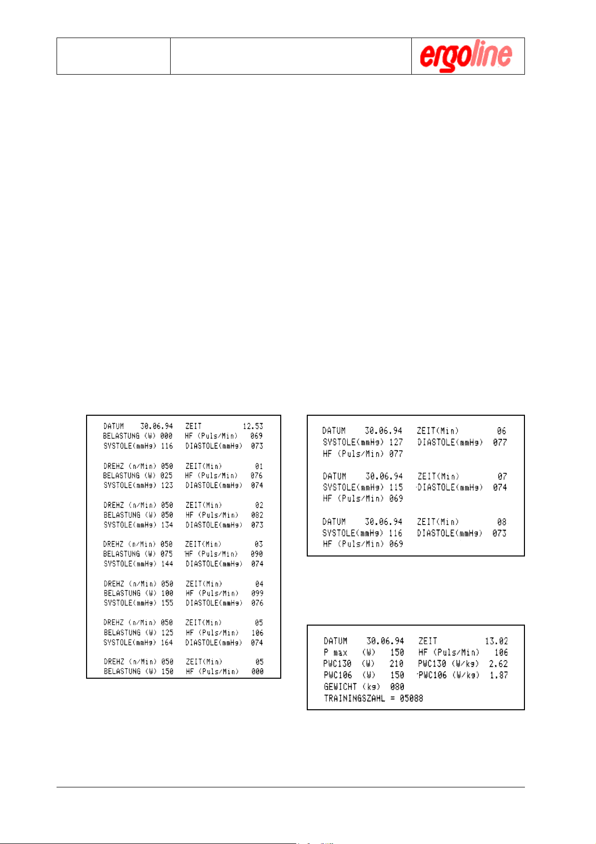
6.6 Ergometric Protocol
An ergometric protocol is recorded during the ergometric session. The protocol is either
produced by the internal printer or by an ECG. Picture below shows such a protocol as
documented by the internal printer. Program parameters were:
heart rate max. = 180, systole max. > 200, diastole max. > 130,
initial load Po = 50 watt, maximum load Pmax. = 999 watt,
blood pressure measurement interval = 01 min.,
load interval = 01 min., load change per interval = 25 watt.
The PWC values to be ascertained were predifined for heart rates between 130 and 150
beats per minute. The values in this protocol are not representative of a patient as they were
generated with a simulator.
quiescent blood pressure
Ergometer
Type er900L
blood pressure measurements
for individual load increments
}
termination of the load program
with termination protocol
blood pressure measurements in
the recuperation phase
}
Version: 12/01
29
end of ergometry with concluding protocol
er900L Operation Manual
Art-Nr: 475.043

Ergometer
Type er900L
6.7 Manual Control of Ergometry session
If necessary, the ergometry session , i.e. the load program may be manually controlled
via the measurement head .
That is done by starting a suitable ergometry program, and then interrupting the automatic sequence of the program at the desired instant by pressing the key „STOP“.
The requested load is then set by means of the white cursor keys.
Start of Ergometry Session
Press the green button „START“ to begin the ergometric session.
Operation Manual
Ergometry process
#
Quiescent Blood Pressure Measurement
Immediately after starting the ergometer, the quiescent blood pressure measurement will be
taken. It is important that the patient remains absolutely calm during this measurement as the
filter parameters for the blood pressure during stress are established by this measurement.
Artefacts during this measurement may lead to false results under stress.
Establishment of the Initial Load P
The load program will begin with initial load Po when
the blood pressure data has been output.
"
"
Enable Manual Control
By pressing button „STOP“, the automatic ergometer control is interrupted.
Increase or decrease Load manually
By pressing the white cursor buttons, the load is adjusted at 5 Watt steps.
Terminate Load Program and change to Recovery Phase
The load program is stopped by pressing the green button “END”, and the recovery phase is
started.
o
#
#
#
The interval of the blood pressure measurement still takes place automati-
!
!
er900L Operation Manual
Art-Nr: 475.043
cally at the preset interval .
Manual control is only possible if following ECG-type is set:
ECG-type P1, P2 or P10 (see Annex A or Annex B.1.1)
30
Version: 12/01

Operation Manual
Configuration
Ergometer
Type er900L
7 Configuration
7.1 General
The ergometrics er900L ergometer has numerous setup options to allow the operator
to adapt the device optimally. The most important configuration support is the monitor
program. The monitor program allows the operator to use a set of menus to modify
parameters.
7.2 Call-up of the Monitor Program
Two yellow buttons on the measurement head are provided for management of the
monitor program. Both of these buttons are at the upper right portion of the keypad and
have the following basic functions:
Call-up monitor program mode, as well as call-up of the various sub-menus. When
in monitor program mode, the sub-menu at the position of the cursor is selected
by pressing button „MONITOR“ once more.
Confirm and save changes made in monitor program or the appropriate submenu as well as exit from monitor program mode or a sub-menu.
The programming diagrams on the next page illustrate the structure of the monitor
program.
Version: 12/01
31
er900L Operation Manual
Art-Nr: 475.043

Ergometer
Type er900L
Operation Manual
Configuration
MONITOR V.XXX
ACTIVATE PROGRAM
ADJUST CLOCK
mmHg - kPa
mmHg - kPa M
mmHg (*)
kPa (*)
$
MONITOR V.XXX
TEST
ADJUST TORQUE
ADJUST OUTPUT
$
ADJUST CLOCK M
YEAR XX MONTH XX
DAY XX HOUR XX
MINUTE XX
$
ACTIVATE PROGRAM M
PROGRAM No X
$
Max.HEARTFREQ. HR < XXX
Max.Syst. S < XXXmmHg
$
ACTIVATE PROGRAM M
max.Diast. D < XXXmmHg
START LOAD Po = XXX W
MAX. LOAD Pmax.=XXX W
$
ACTIVATE PROGRAM M
Interv. BPM = XX min.
PWC = XXX PWC = XXX
TRAININGSIND. [Y/N]
$
ACTIVATE PROGRAM M
LOAD STEP 01 : 12
INTERV.LOAD = XX min.
LOAD CHANGE XXX W
TEST M
+- 5 Va = 5.XX V [ 0.2 ]
$
+ 5 Vd = 5.XX V [ 0.3 ]
+24 V = 2X.X V [ 6V ]
$
LOAD EXT = 000 W TEST M
U-TD = XXX [ 020 - 150 ]
U-DMS = XXX [ 050 - 250 ]
S = XXXmmHg D = XXXmmHg
$
1
$
ADJUST OUTPUT M
LOAD BPM
SYSTOLE DIASTOLE
ADJUST LOAD OUTPUT MM
SET CODE . . .
$
300 W = < >
ADJUST SYS OUTPUT MM
SET CODE . . .
300 mmHg = < >
$
ADJUST TORQUE M
ZERO DMS-AMPL.
TORQUE
ADJUST BPM OUTPUT MM
SET CODE . . .
200 BPM = < >
$
ADJUST DIA OUTPUT MM
SET CODE . . .
$
300 mmHg = < >
$
ZERO DMS-AMPL. MM
SET CODE . . .
U - DMS = XXX [025 - 125]
$
EV.RESET SPRING
TORQUE MM
SET CODE . . .
$
PUT 3 - 6 Kg
WEIGHT = X.XX Kg
er900L Operation Manual
Art-Nr: 475.043
32
Version: 12/01

Operation Manual
Configuration
Ergometer
Type er900L
1
$
MONITOR V.XXX
LOAD INT/EXT
ADJUST LOAD INPUT
ECG RECORD
LOAD INT - EXT M
$
INT [ * ]
EXT [ * ]
ADJUST LOAD INPUT M
$
ZERO LOAD
LOAD EXT
ECG RECORD XX sec M
$
P1 * P5 * P9 * M
P2 * P6 * P10 *
$
P3 * P7 * P11 *
P4 * P8 * P12 *
ZERO LOAD EXT MM
SET CODE . . . .
$
LOAD - ZERO = XXX W
ADJUST LOAD INPUT MM
SET CODE . . .
$
= 000 W < >
$
MONITOR V.XXX
ECG - TYPE
TRANSM.SPEED
LANGUAGE
$
MONITOR V.XXX
CONTR. RPM
CONTR. INT / EXT
RESERVE
TRANSM.SPEED M
$
2400 Baud ( * )
4800 Baud ( * )
LANGUAGE M
$
GER ( * ) ENG ( * )
FRZ ( * )
CONTR. RPM MM
$
ON ( * )
OFF ( * )
CONTR. INT / EXT MM
$
INT ( * )
EXT ( * )
Version: 12/01
33
er900L Operation Manual
Art-Nr: 475.043

Ergometer
Type er900L
Operation Manual
Configuration
7.3 Base Settings
7.3.1 Date and Time
The system has an integrated real-time clock that can be set by the monitor program.
This clock is set correctly when the unit is delivered but may require re-setting, for example when changing from winter time to summer time. Proceed as follows:
" Press the button „MONITOR“
$$
$
$$
MONITOR V.XXX
ACTIVATE PROGRAM
ADJUST CLOCK
mmHg - kPa
$$
$
$$
$$
$
$$
MONITOR V.XXX
ACTIVATE PROGRAM
ADJUST CLOCK
mmHg - kPa
$$
$
$$
$$
$
$$
ADJUST CLOCK M
YEAR XX MONTH XX
DAY XX HOUR XX
MINUTE XX
The monitor main menu will appear in the
display
" Using the cursor buttons in the alpha-
numeric keypad, move the cursor to the
menu item ADJUST CLOCK
" Call up this subprogram by pressing the
button „MONITOR“ again.
" Use the numeric keypad to enter the cor-
rect time and date. The cursor will automatically advance from field to field. Use
the arrow keys to move the cursor to a particular field.
$$
$
$$
%
%
%
er900L Operation Manual
Art-Nr: 475.043
" Confirm that the information is correct by
pressing the button „RETURN“ . The main
menu will then reappear.
You may now proceed to other menu items
or exit the monitor program by pressing the
„RETURN“ key again.
34
Version: 12/01

Operation Manual
Configuration
Ergometer
Type er900L
7.3.2 Select Unit for Pressure Display
It is possible to select either mmHg or the SI unit kPa for use in the printed output.
Proceed as follows:
" Press the button „MONITOR“
$$
$
$$
MONITOR V.XXX
ACTIVATE PROGRAM
ADJUST CLOCK
The monitor main menu will appear in the
display
mmHg - kPa
$$
$
$$
" Using the arrow keys in the alphanumeric
keypad, move the cursor to the menu item
$$
$
$$
„mmHg - kPa“
MONITOR V.XXX
ACTIVATE PROGRAM
ADJUST CLOCK
mmHg - kPa
$$
$
$$
$$
$
$$
mmHg - kPa M
mmHg ( * )
kPa ( * )
$$
$
$$
%
%
%
" Call up this subprogram by pressing the
button „MONITOR“ again.
" Use the arrow keys in the alphanumeric
keypad to move the cursor to the desired
unit of measure.
" Confirm the entry by pressing the button
„RETURN“ . The main menu will then reappear.
You may now proceed to other menu items
or exit the monitor program by pressing the
button „RETURN“ again.
Version: 12/01
35
er900L Operation Manual
Art-Nr: 475.043

Ergometer
Type er900L
Operation Manual
Configuration
7.3.3 ECG Start Pulse Duration (only for remote start of ECG)
The ergometer has a remote start output with which an ECG device can be triggered
(provided that the ECG device has a corresponding input). The feature programmed
below determines the period during which the remote start signal is applied to the output. Signal duration is fully selectable in 1 second steps within a range of 0 - 99. Signal
duration is determined as follows:
" Press the button „MONITOR“
$$
$
$$
MONITOR V.XXX
ACTIVATE PROGRAM
ADJUST CLOCK
The monitor main menu will appear in the
display
mmHg - kPa
$$
$
$$
$$
$
$$
MONITOR V.XXX
LOAD INT/EXT
ADJUST LOAD - INPUT
ECG - RECORD
$$
$
$$
$$
$
$$
ECG - RECORD XX sec M
$$
$
$$
%
%
%
" Using the arrow keys in the alphanumeric
keypad, move the cursor to the menu item
„ECG RECORD“
" Call up this subprogram by pressing the
button „MONITOR“ again.
" Enter the period in seconds using the al-
phanumeric keypad. The cursor will automatically advance.
" Confirm the entry by pressing the „RE-
TURN“ key. The main menu will then re-
appear.
You may now proceed to other menu items
or exit the monitor program by pressing the
button „RETURN“ again.
er900L Operation Manual
Art-Nr: 475.043
36
Version: 12/01

Operation Manual
Configuration
Ergometer
Type er900L
7.3.4 Select LANGUAGE
The language used in the display and on the print-outs may be selected. There are two
versions of software available, each with three languages. The available languages
are: German (GER), French (FRZ), English (ENG), or Spanish (ESP), Italian (ITA), Dutch
(DUT).
" Press the button „MONITOR“
$$
$
$$
MONITOR V.XXX
ACTIVATE PROGRAM
ADJUST CLOCK
The monitor main menu will appear in the
display
mmHg - kPa
$$
$
$$
$$
$
$$
MONITOR V.XXX
ECG - TYP
TRANSM.SPEED
LANGUAGE
$$
$
$$
$$
$
$$
LANGUAGE M
GER ( * ) ENG ( * )
FRZ ( * )
$$
$
$$
%
%
%
" Using the arrow keys in the alphanumeric
keypad, move the cursor to the menu item
„LANGUAGE“
" Call up this subprogram by pressing the
button „MONITOR“ again.
" Use the arrow keys in the alphanumeric
keypad to move the cursor to the desired
language.
" Confirm the entry by pressing the „RE-
TURN“ key. The main menu will then re-
appear.
You may now proceed to other menu items
or exit the monitor program by pressing the
button „RETURN“ again.
Version: 12/01
37
er900L Operation Manual
Art-Nr: 475.043

Ergometer
Type er900L
Operation Manual
Configuration
7.3.5 RPM Control
Sometimes, it may be necessary for the patient to discontinue pedaling for one reason
or another. Normally, when the RPM value drops below the minimum value (30 RPM),
this will lead to an abort of the load program since a defined load is no more present.
Now it is possible to turn off RPM control for these special applications. The load
program is then not aborted, but rather continues regardless of the presence of a minimum RPM value or not. Re-entry into the program is therefore possible at any time.
" Press the button „MONITOR“
$$
$
$$
MONITOR V.XXX
ACTIVATE PROGRAM
ADJUST CLOCK
mmHg - kPa
The monitor main menu will appear in the
display
$$
$
$$
$$
$
$$
MONITOR V.XXX
CONTR. RPM
CONTR. INT / EXT
RESERVE
$$
$
$$
$$
$
$$
CONTR. RPM MM
ON ( * )
OFF ( * )
$$
$
$$
%
%
%
" Using the arrow keys in the alphanumeric
keypad, move the cursor to the menu item
„CONTR: RPM“.
(„CONTR: RPM“ is a main menu option that
will appear eventually as the main menu
scrolls through the display with repeated
pressing of the arrow keys)
" Call up this subprogram by pressing the
button „MONITOR“ again.
" Use the arrow keys in the alphanumeric
keypad to move the cursor to the desired
selection.
" Confirm the entry by pressing the „RE-
TURN“ key. The main menu will then re-
appear.
You may now proceed to other menu items
or exit the monitor program by pressing the
button „RETURN“ again.
er900L Operation Manual
Art-Nr: 475.043
38
Version: 12/01

Operation Manual
Configuration
Ergometer
Type er900L
7.3.6 Other Parameters
Numerous other parameters can be specified by using the monitor program, among
these are:
* analog input/output adjustments, load unit adjustment, etc.
Some of these parameters are code protected and should not be modified by the op-
erator due to safety considerations. Notify your authorized dealer or the ergoline ser-
vice department if you wish to alter any one of these protected parameters.
„Appendix B“ contains setup instructions for the following parameters:
Setting of ECG-Type
Type selection for an attached ECG unit (for data transmission)
TRANSM.SPEED
ECG specific TRANSM.SPEED selection
Toggle between internal and external load control
Determines if load is to be controlled internally (by the ergometer) or externally (by
the ECG unit)
Hardware Tests
Determines if the voltages of the system are correct
Parameters that are
only to be altered by personnel authorized by ergoline :
Blood Pressure Measurement Unit Certification
Test routine that is run by the office of certification
Torque Adjustment
Adjustment of the drive train unit
Analog Output Adjustment
Adjustment of the analog data outputs
Version: 12/01
Analog Input Adjustment
Adjustment of the analog data inputs
39
er900L Operation Manual
Art-Nr: 475.043

Ergometer
Type er900L
Operation Manual
Configuration
7.4 Defining an Ergometry Program
The operator may select from 10 different ergometric programs when using the
ergometrics er900L. Of these 10 programs, eight are fully programmable, one program offers automatic loading and one program is for pulse-steady-state training.
Ergometric program definition is only possible when the ergometer is controlled
!
!
internally, i.e. not controlled by a PC or ECG unit.
Mixed control is also possible, that is, normal control is internal and, when needed,
control may be transferred to an external device. For mixed control operations
one should ensure that program 8 can be used as a buffer for several interface
modes. Therefore, for mixed control operations only programs 0 through 7, or 9
may be used since program 8 will be used for switching the control type.
The monitor program can be used to establish a basic stress program. Program creation is done as follows:
$$
$
$$
MONITOR V.XXX
ACTIVATE PROGRAM
ADJUST CLOCK
mmHg - kPa
$$
$
$$
$$
$
$$
ACTIVATE PROGRAM M
Program No 0
max. HEARTFREQ. HF < XXX
max. Syst. S < XXX mmHg
$$
$
$$
%
%
%
" Press the button „MONITOR“
The monitor main menu will appear in the
display
" Call up this subprogram by pressing the
button „MONITOR“ once more.
" Select the program number that you wish
to program by entering the program number with the numeric keypad.
" Program the selected stress program as
described in this chapter.
" Confirm the entry by pressing the „RE-
TURN“ key. The main menu will then re-
appear.
er900L Operation Manual
Art-Nr: 475.043
You may now proceed to other menu items,
e.g. defining another program, the monitor program must be called up again.
See above.
40
Version: 12/01

Operation Manual
Configuration
Ergometer
Type er900L
7.4.1 Setup of Automatic Program 0
Automatic program 0 is for the fully automated testing of patients with unknown circulation condition, in particular, weak patients. The ergometer’s control computer uses this
program to test the patient’s circulation response across two or three different but specific load increments. The computer then determines three standard load increments
within which the pre-set maximum heart rate should be attained. The standard load
increments and the corresponding time intervals are taken from the WHO table for stress
analysis.
%
%
$$
$
$$
ACTIVATE PROGRAM M
Program No 0
max. HEARTFREQ. HF < XXX
max. Syst. S < XXX mmHg
$$
$
$$
ACTIVATE PROGRAM M
max . Diast . D< XXX
START LOAD Po = XXX W
max. LOAD Pmax = XXX W
$$
$
$$
ACTIVATE PROGRAM M
Interv . BPM = XX min . 0
PWC = XXX PWC = XXX
TRAININGIND. [ Y / N ] N
$$
$
$$
%
%
%
" Call up program creation as described in the
preceding section.
" Select program 0 in the field „Program No“.
" You can now assign the individual parameters.
The meaning of these parameters for this
special analysis program is described below.
" The cursor will automatically skip to the next
field when entry is complete for the current
field. Complete entry must be made in each
field in accordance with the number of character positions provided. The arrow keys may
be used to move to any field desired. The
display will scroll automatically when the upper or lower display margins are reached.
" Close data entry with the „RETURN“ key.
Now program 0 is configured in accordance
with your choices. Any parameter may still
be changed at the beginning of ergometry for
a specific ergometric run.
The meaning of the various training parameters:
max. Heartfreq. = heart rate which is to be attained in three standard load steps. When
this goal has been reached the program will stop. (Any one of the alarm
conditions described below will also cause program termination)
max. Syst. = alarm parameter, when reached will cause program termination
max. Diast. = alarm parameter, when reached will cause program termination
Start load = load value with which the system begins stressing the patient.
max. Load = maximum load value that is not to be exceeded
Interv. BPM = interval at which blood pressure readings are to be made
PWC = heart rate value at which a PWC value is to be determined (see Ap-
pendix D.1)
TRAININGIND. = see appendix (see Appendix D.2)
Version: 12/01
41
er900L Operation Manual
Art-Nr: 475.043

Ergometer
Type er900L
7.4.2 Definition of Programs 1-8
The operator has the choice of eight stress programs that are freely programmable to
specific requirements on the ergometrics er900. In these eight programs, all control
and alarm parameters are fully selectable. As with programs 0 and 9, the setup accomplished with the monitor program represents a basic setup that can still be changed for
any specific ergometry run at the beginning of that particular ergometry.
Program 8 is an exception to this rule in case the ergometer is operated in mixed-
!
ACTIVATE PROGRAM M
Programm No 0
max. HEARTFREQ. HF < XXX
max. Syst. S < XXX mmHg
control mode. That is, when the ergometer switches back and forth between internal and external (from an ECG or PC) control. Program 8 should not be used in
such cases as it is used as an interface buffer for various external control modes
which will cause parameters to be lost.
%
%
%
$$
$
$$
Operation Manual
Configuration
" Call up program definition as described in the
preceding section.
" Select the desired program to be modified
(1-8) in the field „Program No“.
$$
$
$$
ACTIVATE PROGRAM M
max . Diast . D< XXX
START LOAD Po = XXX W
max . LOAD Pmax = XXX W
$$
$
$$
ACTIVATE PROGRAM M
Interv . BPM = XX min . 0
PWC = XXX PWC = XXX
TRAININGIND. [ J / N ] N
$$
$
$$
ACTIVATE PROGRAM M
LOAD STEP 01 : 12 0
INTERV. LOAD = XX min .
LOAD INCREMENT XXX W
$$
$
$$
%
%
%
" Now you can set the individual parameters.
The significance of the parameters for this
special analysis program are described below.
The cursor will automatically skip to the next
field when entry is complete for the current
field. Complete entry must be made in each
field in accordance with the number of character positions provided
(Example: Start Load Po = 3 characters; entry value of 50 watt would be entered as Po =
050W).
The arrow keys may be used to move to any
field desired. The display will scroll automatically when the upper or lower display margins
are reached.
" Close data entry with button „RETURN“ . The
selected program is now configured according to your choices. Any parameter may still
be changed at the beginning of ergometry for
a specific ergometric run.
er900L Operation Manual
Art-Nr: 475.043
42
Version: 12/01

Operation Manual
Configuration
The meaning of the various training parameters :
max. Heartfreq = alarm parameter, when reached will cause program termination
max. Systole = alarm parameter, when reached will cause program termination
max. Diastole = alarm parameter, when reached will cause program termination
Start Load = load value with which the system begins stressing the patient.
The time interval for the initial load is specified by the interval for
the first load increment.
max. Load = maximum load value that is not to be exceeded
Interv. BPM = interval at which blood pressure readings are to be made
PWC = heart rate value at which a PWC value is to be determined
(PWC value see appendix)
TRAININGSIND. = see appendix
LOAD STEPS = twelve load steps may be programmed individually. An entry
made into any one of these load steps will cause the same value
to be entered into all subsequent load steps.
Ergometer
Type er900L
INTERV.LOAD = time interval of the load, that is elapsed time for the respective
load step.
LOAD CHANGE = amount of load change with respect to the previous load step
Example: Initial load = 025 W
Load change 1 = 015 W +
__________
Load step 1 = 040 W
In Annex C attached to this operator’s manual, you will find programming
!
forms. We recommend that these forms be filled out before actually programming the ergometer. Save these forms as they will be useful if something should happen to the ergometer.
Version: 12/01
43
er900L Operation Manual
Art-Nr: 475.043

Ergometer
Type er900L
Operation Manual
Configuration
7.4.3 Definition of Program 9 for Pulse-Steady-State Training
Program 9 offers pulse-steady-state training capability. A continuously available heart
rate input is prerequisite for this program. Heart rate input can be accomplished in
various ways. You can attach an ear/finger clip, a pulse monitor (such as the Polar
Pacer) or connect a QRS trigger output from an ECG device being used (see Annex E
to this operator’s manual).
%
%
%
$$
$
$$
ACTIVATE PROGRAM M
Program No 0 > X<
max. HEARTFREQ. HF < XXX
max. Syst. S < XXX mmHg
$$
$
$$
ACTIVATE PROGRAM M
max . Diast . D< XXX
START LOAD Po = XXX W
max . LOAD Pmax = XXX W
$$
$
$$
ACTIVATE PROGRAM M
Interv . BPM = XX min . 0
PWC = XXX PWC = XXX
TRAININGIND. [ Y / N ] N
$$
$
$$
ACTIVATE PROGRAM M
LOAD STEP 01 - 12 0
INTERV. LOAD = XX min .
LOAD CHANGE XXX W
" Call up program creation as described in the
preceding section.
" Select program 9 in the field „Program No“.
" Now you can set the individual parameters.
The significance of the parameters for this
special analysis program are described below.
The cursor will automatically skip to the next
field when entry is complete for the current
field. Complete entry must be made in each
field in accordance with the number of character positions provided
(Example: Start Load Po = 3 characters; entry value of 50 watt would be entered as &P
= 050W).
The arrow keys may be used to move to any
field desired. The display will scroll automatically when the upper or lower display margins
are reached.
0
$$
$
$$
%
%
%
er900L Operation Manual
Art-Nr: 475.043
" Close data entry with the „RETURN“ key.
Now program 9 is configured in accordance
with your choices. Any parameter may still be
changed at the beginning of ergometry for a
specific ergometric run.
44
Version: 12/01

Operation Manual
Configuration
The meaning of the various training parameters:
max. Heartfreq. = This is the pulse-steady-state limit for heart rate that is to be used
in this training. When this limit is reached, the ergometer will
take over complete load control to ensure that the patient’s heart
rate remains stable at this level (by lowering and raising the load
automatically).
max. Systole = Alarm parameter, when reached will cause program termination
max. Diastole = Alarm parameter, when reached will cause program termination
Start Load = Load value with which the system begins stressing the patient.
The time interval for the initial load is specified by the interval
for the first load increment.
max. Load = Maximum load value that is not to be exceeded
Interv. BPM = Interval at which blood pressure readings are to be made.
Ergometer
Type er900L
PWC = heart rate value at which a PWC value is to be determined
(see ANNEX D.1)
TRAININGIND. = see ANNEX D.2
LOAD STEP = Twelve load steps may be individually programmed. An entry
made into any one of these load steps will cause the same
value to be entered into all subsequent load steps.
Interv. LOAD = Time interval of the load, that is elapsed time for the respective
load step.
LOAD CHANGE = amount of load change with respect to the previous load step
Example: Initial load = 025W
Load change 1 = 015W +
------------
LOAD step 1 = 040 W
When running pulse-steady-state training, the significance of the load in-
!
crements and load changes is limited to the preliminary training prior to
reaching the desired maximum heart rate (Pulse-Steady-State limit). Load
control is dependent upon heart rate response after this limit is reached.
Version: 12/01
Pulse-Steady-State training may only be carried out when the heart rate is
continuously provided to the system.
45
er900L Operation Manual
Art-Nr: 475.043

Ergometer
Type er900L
Operation Manual
Structure of Programs
8 Structure of Programs
8.1 General Structure of Programs 1-8
8.1.1 Factory Settings
Die Programs 1-8 can be individually programmed for the testing of various patient
groups such that at the push of a button the right program is at hand. Programs 1-4
have been pre-programmed with sample programs by ergoline prior to delivery. These
programs are only exemplary and can certainly be changed.
weak patients
(approx. 45kg
body weight)
Program No. 1 2 3 4
max. heart rate 150 150 150 170
max. systolic pressure 230 230 230 240
max. diastolic pressure 130 130 120 100
Start load Po 25 50 50 50
max. Load Pmax 999 999 999 999
Interval BP in min. 1 1 2 2
PWC 110 130 130 150
PWC 130 150 150 170
Training Index N J J J
Load steps 01 01 01 01
02 02 02 02
... 03
... .
... .
moderately strong
patients (especially
women)
normally strong
patients
(especially athletic
women and men)
strong patients,
active sports men
and heavy laborers
Interval load 01 01 01 01
in min 01 01 02 02
Load change 010 010 025 025
in Watts 010 01 0 025 02 5
er900L Operation Manual
Art-Nr: 475.043
... 02
... .
... .
. . . 025
... .
... .
46
Version: 12/01

Operation Manual
Structure of Programs
Ergometer
Type er900L
8.1.2 Creating Your Own Load Program
Programs 1-8 were intended to be programmed from the monitor program, as described in this manual, for various pre-defined patient groups. This allows you to select
the appropriate program for a patient at the touch of a button. This gives you basic
settings with which the stress test of the patient can be performed. You may still change
any of the parameters prior to starting ergometry. Such a parameter change, that is not
accomplished within the monitor program, is only temporary and effective for this specific one ergometry. Such changes are voided at the end of the ergometry.
This is why, when you use the monitor program to program the load programs, you need
to proceed such that only the absolute limits for an entire patient group be pre-set as
alarm parameters. The patient specific alarm parameter should then be entered when
the program is called up. In general, eight programs with differing load characteristics
are adequate to serve various patient group types if patients are grouped by their load
requirement patterns. The flowchart below should serve to clarify the process of an
ergometry.
Determine the correct patient group for the patient.
Select the appropriate program for the patient.
If necessary, change circulation alarm parameters
Start the program (quiescent blood pressure measurement)
Print-out of the resulting data
Start load program at P
o
Print-out of the loaded data with every load change
and/or every blood pressure measurement
Load increments 1...12 as programmed
Load program termination (caused by reaching an alarm parameter,
dropping below the minimum RPM rating of 25 RPM or because the „END“
key was pressed - transition to the recuperation phase
Version: 12/01
Print-out of measurement results for the on-going
blood pressure measurements
Terminate ergometry by again pressing the „END“ key
Output of the summary protocol
47
er900L Operation Manual
Art-Nr: 475.043

Ergometer
Type er900L
Operation Manual
Structure of Programs
8.2 Systematic Setup of Programs
8.2.1 Setup of Automatic Load Program 0
Except for initial load and maximum load values, program 0 does not permit any load
settings from the operator. Individual load increments are not programmable. The loading process is determined automatically by the ergometer during the ergometry process and is only dependent upon the circulation response of the patient.
Program 0 is intended for critical patients whose circulatory condition is unknown. It is
therefore necessary that the parameters be accordingly conservative. Establish initial
load and alarm parameter values such that even very weak patients will not be overstressed. Select blood pressure measurement intervals as short as reasonable in order to guarantee the best possible surveillance over the patient’s circulatory condition.
The program will calculate three standard load increments of 5, 10 or 25 watt within
which the patient can reach the pre-set heart rate. The resulting protocol data will enable you to subsequently classify the patient into one of the patient groups for which you
have a specific program (1-8).
Even with program 0 it is possible to make temporary alterations to any parameter for
the specific ergometric process. The flowchart below should clarify the ergometric process for program 0.
Continuous doctor’s attention is also required for patients who are
!
stressed with automatic program 0 since the circulatory response is not
continuously monitored. Parameters can change abruptly between individual blood pressure measurements without the system being able to
appropriately counteract.
er900L Operation Manual
Art-Nr: 475.043
48
Version: 12/01

Program flowchart:
Start program (quiescent blood pressure measurement)
Operation Manual
Structure of Programs
Patients with unknown circulatory conditions
select program 0
If necessary, change circulation alarm parameters
Ergometer
Type er900L
Print-out of resulting data
Load program start at Po
Print-out of the loaded data with every blood pressure measurement
Calculation of standard increments via 2-3 free load increments, subsequently
stressing with 3 standard load increments to reach the max. heart rate
Load program termination (caused by reaching an alarm parameter, dropping
below the minimum RPM rating of 25 RPM or because
the „END“ key was pressed - transition to the recovery phase
Print-out of measurement results for the on-going
blood pressure measurements
Terminate ergometry by again pressing the „END“ key
Output of the summary protocol
Version: 12/01
49
er900L Operation Manual
Art-Nr: 475.043

Ergometer
Type er900L
Pay attention to the execution of the program when programming. The base values that
were entered via the monitor program are not necessarily those that are appropriate for
a given patient. When programming you should only enter upper limit values that apply
to the largest possible group of patients. Any parameter can still be changed for any
specific ergometric run such that the parameters are tailored to the patient. You should
also select alarm values that will prevent over stressing even weaker patients but still
allow for a meaningful test. Select an initial load that will not overburden the weaker
patients. If you don’t the circulation condition will show false results and automatic
ergometry is then impossible.
In general, automatic ergometry is only used for acute, mostly weak, patients. Accordingly, you should set the parameters at relatively low levels.
Heart rate is one exception in these parameters. It should only be entered via the monitor program as a nominal value. Adapt this value however, to each individual patient,
prior to ergometry. The ergometer works toward attaining this maximum heart rate.
Program 0 will try to reach the maximum heart rate by using three standard load increments. You should, therefore, set the maximum heart rate in accordance with the capabilities of the individual patient so as to avoid excessive stresses. It is also astute to
provide the ergometer with a continuous heart rate. This can be done with an ear/finger
clip, a pulse monitor or with a heart rate feedback from an ECG unit (see appendix).
Operation Manual
Structure of Programs
Enter the maximum heart rate via the monitor program only as a nominal value but
!
!
adapt this value to each individual patient prior to ergometry.
You should write your program on one of the programming forms before entering the
program on the console of the ergometer. The programming form is an aid that helps
the operator maintain an overview of the various parameters. The program forms also
represent a permanent record of the programs that are available if the unit should malfunction. You will find blank programming forms in the appendix to this manual. An example of a programming form already filled out can be found in this chapter.
Write your programs on the program forms (as found in the appendix of this manual)
before entering them in the console of the ergometer. This contributes to clarity
and proper record keeping.
er900L Operation Manual
Art-Nr: 475.043
50
Version: 12/01

Operation Manual
Structure of Programs
Program Listing
Program No.: 0
Ergometer
Type er900L
maximum heart rate HR =
maximum Systole S =
maximum Diastole D =
initial load Po =
maximum load Pmax =
blood press. measurement interv. INTERV.BDM =
desired PWC value PWC =
Trainingsind. J N
140140
140 1/min.
140140
230230
230 mmHg (kPa)
230230
130130
130 mmHg (kPa)
130130
2525
25 watt
2525
999999
999 watt
999999
0101
01 min.
0101
130130
130 PWC =
130130
Load increments:
Step 1 Step 2
Load interval = min. Load interval = min.
Load change = watt Load change = watt
Step 3 Step 4
Load interval = min. Load interval = min.
150150
150
150150
Load change = watt Load change = watt
Step 5 Step 6
Load interval = min. Load interval = min.
Load change = watt Load change = watt
Step 7 Step 8
Load interval = min. Load interval = min.
Load change = watt Load change = watt
Step 9 Step 10
Load interval = min. Load interval = min.
Load change = watt Load change = watt
Step 11 Step 12
Load interval = min. Load interval = min.
Load change = watt Load change = watt
Version: 12/01
51
er900L Operation Manual
Art-Nr: 475.043

Ergometer
Type er900L
Operation Manual
Structure of Programs
8.2.2 Setup of the Fully Programmable Load Programs 1-8
Programs 1-8 serve to provide the user with a stress program spectrum that will accommodate the patient groups that are to undergo ergometry. Every parameter in these
eight programs is freely definable and will be upheld by the ergometer unless an alarm
parameter is exceeded or a manual change is made to ergometry by the operator.
In this manual you will find examples of such patient group oriented programs. These
example programs are the same as those that are factory pre-programmed prior to
shipment. Naturally, these programs can also be overwritten and individually adapted
to the wishes and needs of the user.
Program Flow:
Classify the patient as belonging to a particular patient group.
Select the appropriate program (1-8).
If necessary, change circulation alarm parameters
Start program (quiescent blood pressure measurement)
Print-out of resulting data
Load program start at Po
Print-out of the loaded data with every blood pressure measurement
Increment the load according to the pre-programmed
load increments at the pre-programmed intervals
Load program termination (caused by reaching an alarm parameter,
dropping below the minimum RPM rating of 25 RPM or because the „END“ key
was pressed - transition to the recuperation phase
Print-out of measurement results for the on-going
blood pressure measurements
Terminate ergometry by again pressing the „END“ key
er900L Operation Manual
Art-Nr: 475.043
Output of the summary protocol
52
Version: 12/01

Operation Manual
Pay attention to the execution of the program when programming. Determine the parameters for the various patient groups before you begin to program. Select alarm and
load parameters according to average strength characteristics of patient groups. Select parameter values such that most individuals in the group require no parameter
changes and those that may become necessary are minor. Reserve a program, preferably program 8, for special patients that require an individualized program. Here then,
you can create experimental programs suited to the patient’s specific requirements. To
make such and experimental program, set all of the parameters for the selected program (e.g. program 8) to minimum or maximum values, i.e. 0 or 999, so that all automatic control functions are turned off. Then you can enter the actually desired values for
this specific ergometry just before starting the session.
For special ergometrics, setup one program (e.g. program 8) as experi-
!!
!
!!
You should write your program on one of the programming forms before entering the
program on the console of the ergometer. The programming form is an aid that helps
the operator maintain an overview of the various parameters. The program forms also
represent a permanent record of the programs that are available if the unit should malfunction. You will find blank programming forms in the appendix to this manual.
mental with all maximum or minimum parameter values.
Ergometer
Type er900L
!!
!
!!
Write your programs on the program forms (as found in the appendix to
this manual) before entering them in the console of the ergometer. This
contributes to clarity and proper record keeping.
Version: 12/01
53
er900L Operation Manual
Art-Nr: 475.043

Ergometer
Type er900L
Operation Manual
Structure of Programs
8.2.3 Setup of Program 9, Steady-Pulse (Heart & Circulation Training)
Program 9 is for pulse-steady-state training. The ergometer increments the load from
the outset of training according to your parameters. Upon reaching the maximum heart
rate setting, instead of causing program termination, the unit switches over to pulsesteady-state control. That means that load changes are calculated to maintain this
heart rate. It is absolutely necessary to provide the ergometer with a continuous heart
rate signal when running the pulse-steady-state program. This can be accomplished
with an ear/finger clip, a pulse monitor or a heart rate feedback from and ECG device.
Once reached, the ergometer will hold the maximum heart rate value stable until an
additional alarm parameter is exceeded or the training session is manually ended by
the operator.
Program Flow:
Patient for pulse-steady-state training
select program 9
Possible change of the maximum heart rate
Start program (quiescent blood pressure measurement)
Print-out of resulting data
Load program start at P
o
Print-out of the loaded data with every blood pressure measurement
Increment the load according to the pre-programmed load increments at the
pre-programmed intervals until the max. heart rate value is reached
Transition to pulse-steady-state control. Load will be
automatically altered in response to the heart rate.
Load program termination (caused by reaching an alarm parameter,
dropping below the minimum RPM rating of 25 RPM or because the „END“
key was pressed - transition to the recuperation phase
Print-out of measurement results for the on-going
Terminate ergometry by again pressing the „END“ key
er900L Operation Manual
Art-Nr: 475.043
blood pressure measurements
Output of the summary protocol
54
Version: 12/01

Operation Manual
Structure of Programs
Pay attention to the execution of the program when programming. Since program 9 is
a pure training program, alarm parameters (except for heart rate) should be chosen
that any danger to the patient is remote. Select a warm-up load parameter (used until
reaching the max. heart rate value set) such that reaching the heart rate value will not go
to quickly or take too long. When the warm-up phase is too short, reasonable pulsesteady-state training is not possible as the circulatory system has not yet adjusted to
the load. When the warm-up phase is too long, the patient is already tired before the
actual training phase has been reached.
Program 9 is purely a training program. Parameters must be selected that
!
reflect the requirements of this mode of operation (as opposed to programs 0-8).
You should write your program on one of the programming forms before entering the
program on the console of the ergometer. The programming form is an aid that helps
the operator maintain an overview of the various parameters. The program forms also
represent a permanent record of the programs that are available if the unit should malfunction. You will find blank programming forms in the appendix to this Operation Manual.
Ergometer
Type er900L
!
Write your programs on the program forms (as found in the appendix to
this manual) before entering them in the console of the ergometer. This
contributes to clarity and proper record keeping.
Version: 12/01
55
er900L Operation Manual
Art-Nr: 475.043

Ergometer
Type er900L
9. Cleaning
The unit, blood pressure cuff and related accessories should be regularly cleaned,
!
9.1 Cleaning the Unit
!
if required, daily.
Important !!
Be sure to disconnect the power cord prior to cleaning the unit.
Use a soft cloth moistened with a mild cleanser to wipe off the unit as needed.
Ensure that the cloth is not fully saturated. A fully saturated cloth may allow
liquid to enter the unit and cause a defect.
Operation Manual
Cleaning
Do not use strong household cleaners or alcoholic disinfectants to clean the unit. This may lead to defects and/or damage the finish of unit, upholstery and/or cuff.
9.2 Cleaning the Blood Pressure Cuff
The blood pressure cuff may also be cleaned with a mild soapsuds. For disinfection
!!
!
!!
of the cuff, only alcoholic disinfectants may be used. Other disinfectants, or the use of
strong cleansers may damage the cuff and lead to defects.
The microphone should also be cleaned at regular intervals.
To clean the microphone, remove it from its pocket in the
cuff.
For cleaning, only use a mild detergent or alcohol.
After cleaning, rinse the cuff surface with distilled
water.
After cleaning, pay attention to correct microphone position in the red pocket of the
cuff.
The brass coloured side of microphone points at the arteria.
Cuff and hose must never be soaked in cleansers or disinfectants.
Defects caused by improper detergent and disinfectants as well as de-
!!
!
!!
er900L Operation Manual
Art-Nr: 475.043
fects originating from insufficient cleaning of the unit are excluded from
the guarantee.
56
Version: 12/01
B

Operation Manual
Appendix A: Interfaces
Ergometer
Type er900L
Appendix A: Interfaces
The ergometer er900L features a number of interfaces. Data can be transmitted or received
by the ergometer in analog or digital modes. Complete external control of the ergometer from
a PC or ECG is possible via these interfaces. These same interfaces also capable of transferring information to external devices (PC or ECG). ergoline provides a wide palette of
control variations using a variety of control protocols with a combination of analog and digital
signals. These protocols permit the ergometer’s connection to practically all ECG units on
the market that have an ergometric program. You will find the interface protocols in this appendix.
A.1 Input and Output Pin Specifications
Pin1 = TxD Pin1 = External Load Pin1 = +5V
Pin2 = GND Pin2 = Remote Start BPM Pin2 = EKG input.
Pin3 = RTS Pin3 = Remote Start EKG Pin3 = N C
Pin4 = CTS Pin4 = Pulse output Pin4 = NC
Pin5 = RxD Pin5 = Load output Pin5 = Opto input
Version: 12/01
Pin6 = Diastole output Pin6 = GND
Pin7 = ECG input
Pin8 = Systole output
Housing = GND
Inputs = Kursiv Outputs = Normal
57
Analog
Analog
er900L Operation Manual
Art-Nr: 475.043

Ergometer
Type er900L
Interface for digital data transfer from er900 to PC or ECG
Voltages:
Baud rate:
Operation Manual
Appendix A: Interfaces
ergometrics er900
Interface ECG Type P1
Software Version V.243
with internal control of er900
logic low logic high
Transmit Output (Pin 1) >+7 V <-7 V
Receive Input (Pin 5) >+3 V <-3 V
2400/4800 Baud
Protocol:
Format ASCII
Start bit 1
Data bits 8
Stop bit 1
Parity None
Handshake None
Hardware Connection :
er900L Operation Manual
Art-Nr: 475.043
58
Pin 1 Transmit (Output)
Pin 2 GND
Pin 3 NC
Pin 4 CTS
Pin 5 Receive (Input)
Version: 12/01

Transmission Protocol :
Operation Manual
Appendix A: Interfaces
Ergometer
Type er900L
DATE 14.06.91 TIME 08.23
LOAD (watt) 000 HR (pulse/min) XXX
SYSTOLE(mmHg) XXX DIASTOLE(mmHg) XXX
TORQUE (n/min) XXX TIME 08.24
LOAD (watt) XXX HR (pulse/min) XXX
SYSTOLE(mmHg) XXX DIASTOLE(mmHg) XXX
•
•
•
TORQUE (n/min) XXX TIME 08.27
LOAD (watt) XXX HR (pulse/min) XXX
SYSTOLE(mmHg) XXX DIASTOLE(mmHg) XXX
TORQUE (n/min) XXX TIME 08.27
LOAD (watt) XXX HR (pulse/min) XXX
DATE 14.06.91 TIME 08.28
SYSTOLE(mmHg) XXX DIASTOLE(mmHg) XXX
HR (pulse/min) XXX
Protocol of quiescent
state
Protocol of first load
step
Protocol of fourth
load step
Protocol of load
program termination
Protocol of first
recuperation audit
DATE 14.06.91 TIME 08.29
SYSTOLE(mmHg) XXX DIASTOLE(mmHg) XXX
Protocol of second
recuperation audit
HR (pulse/min) XXX
DATE 14.06.94 TIME 0829
P max (watt) XXX HR (pulse/min) XXX
PWC110 (watt) XXX PWC110 (watt/kg) XXX
PWC130 (watt) XXX PWC130 (watt/kg) XXX
Summary protocol at
the end of the entire
ergometry
PWCXXX (watt) XXX PWCXXX (watt/kg) XXX
TRAININGSIND. = XXXXX
A protocol will automatically be produced at every blood pressure measurement and at every load increment. This data will be sent to the RS-232 interface without a prompt, command, or service request from the external device.
Control of load and blood pressure measurements as well as the monitoring of alarm parameters is handled internally from the console of the ergometer.
Version: 12/01
59
er900L Operation Manual
Art-Nr: 475.043

Ergometer
Type er900L
Interface for digital data transfer from er900 to PC or ECG
Voltages:
Baud rate:
Operation Manual
Appendix A: Interfaces
ergometrics er900
Interface ECG Type P2
Software Version V.243
with internal control of er900
logic low logic high
Transmit Output (Pin 1) >+7 V <-7 V
Receive Input (Pin 5) >+3 V <-3 V
2400/4800 Baud
Protocol:
Format ASCII
Start bit 1
Data bits 8
Stop bit 1
Parity None
Handshake None
Hardware Connection :
er900L Operation Manual
Art-Nr: 475.043
60
Pin 1 Transmit (Output)
Pin 2 GND
Pin 3 Pin 4 Pin 5 Receive (Input)
Version: 12/01

Transmission Protocol
Operation Manual
Appendix A: Interfaces
Ergometer
Type er900L
DATE 14.06.91 TIME 08.23
LOAD (watt) 000 HR (pulse/min) XXX
SYSTOLE(mmHg) XXX DIASTOLE(mmHg) XXX
LOAD (watt) XXX
LOAD (watt) XXX
TORQUE (n(min) XXX TIME 08.24
LOAD (watt) XXX HR (pulse/min) XXX
SYSTOLE(mmHg) XXX DIASTOLE(mmHg) XXX
LOAD (watt) XXX
LOAD (watt) XXX
TORQUE (n(min) XXX TIME 08.27
LOAD (watt) XXX HR (pulse/min) XXX
SYSTOLE(mmHg) XXX DIASTOLE(mmHg) XXX
LOAD (watt) XXX
LOAD (watt) XXX
Protocol of
quiescent state
Load rep., begin increm.
Load rep., end increm.
Protocol of first load step
Load rep., begin increm.
Load rep., end increm.
Protocol of fourth
load step
Load rep., begin increm.
Load rep., end increm.
TORQUE (n(min) XXX TIME 08.27
LOAD (watt) XXX HR (pulse/min) XXX
SYSTOLE(mmHg) XXX DIASTOLE(mmHg) XXX
LOAD (watt) XXX
LOAD (watt) XXX
DATE 14.06.91 TIME 08.28
SYSTOLE(mmHg) XXX DIASTOLE(mmHg) XXX
HR (pulse/min) XXX
DATE 14.06.91 TIME 08.29
SYSTOLE(mmHg) XXX DIASTOLE(mmHg) XXX
HR (pulse/min) XXX
DATE 14.06.94 TIME 0829
P max (watt) XXX HR (pulse/min) XXX
PWC110 (watt) XXX PWC110 (watt/kg) XXX
PWC130 (watt) XXX PWC130 (watt/kg) XXX
PWCXXX (watt) XXX PWCXXX (watt/kg) XXX
TRAININGSIND. = XXXXX
Protocol of load
program termination
Load rep., begin increm.
Load rep., end increm.
Protocol of first
recuperation audit
Protocol of second
recuperation audit
Summary protocol at
the end of the entire ergometry
Version: 12/01
61
er900L Operation Manual
Art-Nr: 475.043

Ergometer
Type er900L
Operation Manual
Appendix A: Interfaces
ergometrics er900
Interface ECG Type P3
Software Version V.243
Interface for digital data transfer from er900 to PC or ECG with con-
trol via PC or ECG
Voltages:
logic low logic high
Transmit Output (Pin 1) >+7 V <-7 V
Receive Input (Pin 5) >+3 V <-3 V
Baud rate:
2400/4800 Baud
Protocol:
Format ASCII
Start bit 1
Data bits 8
Stop bit 1
Parity None
Handshake Full Duplex
Hardware Connection :
er900L Operation Manual
Art-Nr: 475.043
62
Pin 1 Transmit (Output)
Pin 2 GND
Pin 3 RTS
Pin 4 CTS
Pin 5 Receive (Input)
Version: 12/01

Operation Manual
Appendix A: Interfaces
Ergometer
Type er900L
Transmission Protocol :
Command from PC Response Description
(ECG) from er900
X <CR> --- Preamble for transmission of the load target value. The
load value must follow this command in a three digit
format (one digit per character).
Target load as three individual characters. The interval
between characters should be less than <200ms.
x-x-x <CR> x-x-x-<CR><LF (if the time between characters exceeds 300ms than
the command will be not accepted). The characters will
be echoed back to the sending device.
Start of quiescent blood pressure measurement.
S <CR> --- At the end of blood the pressure measurement , the
preset load ( previous „X“ command) will be applied.
Start of ergometry with load preset (previous „X“
s <CR> --- command). Each load increment requires another „s“
command.
Request of current load.
W <CR> xxx <CR><LF> Output of current load in W.
Request of current rpm value
D <CR> n xxx <CR> Output of current rpm value in 1/min.
Request of current heart rate
H <CR> H xxx <CR> Output of current heart rate in 1/min.
Request of current measurement results.
M <CR> see „string“ The load step number will be incremented with each „s“
or „S“ command received.
First time issued = terminate load phase and
F <CR> --- change-over to recovery phase
2nd time issued = end of complete ergometry.
Identification string of the ergometer. The string contains the
device type 0900-, ECG interface type set (interface protocol) -
P03 - and Software version number - VXXX-.
Y oder I <CR> 0900P03VXXX When „F“ was first sent to terminate the load phase,
<CR> the "I" command can also be used to terminate the complete
ergometry..
String response to the „M“ command:
NR.xx,SYST:xxxmmHg,DIAST:xxxmmHg,Puls:xxx/min
Remark:
W xxx <CR>
command value(e.g. load value) carriage return (end of line)
Version: 12/01
63
er900L Operation Manual
Art-Nr: 475.043

Ergometer
Type er900L
Operation Manual
Appendix A: Interfaces
ergometrics er900
Interface ECG Type P4
Software Version V.243
Interface for digital data transfer from er900 to an ECG,
with analog control via the ECG
Voltages:
Digital logic low logic high
Transmit Output (Pin 1) >+7V <-7V
Receive Input (Pin 5) >+3V <-3V
Analog minimal maximal resolution
Load argument (input) 0V 5V adjustable
Load return (output) 0V 6V adjustable
RPM return (output) 0V 6V 1V = 50 1/
Baudrate : 2400 or 4800 Baud
Protocol:
Format ASCII
Start bit 1 Remark: Applies only to the RS-232
Data bits 8 digital interface
Stop bit 1
Parity None
Handshake None
min
Hardware Connections :
er900L Operation Manual
Art-Nr: 475.043
64
Pin 1 Transmit (Output)
Pin 2 GND
Pin 3 NC
Pin 4 CTS
Pin 5 Receive (Input)
Pin 1 = Load argument (input)
Pin 2 = Remote Start BPM (input)
Pin 3 = Remote Start ECG (output)
Pin 4 = Pulse frequency (output)
Pin 5 = Current load (output)
Pin 6 = Current diastole (output)
Pin 7 = QRS signal (input)
Pin 8 = Systole (output)
Case = GND
Version: 12/01

Operation Manual
Appendix A: Interfaces
Ergometer
Type er900L
Transmission Protocol:
In contrast to purely digital transmission, ECG type P4 protocol always responds, upon
demand, with a standardized data record. The string consists of 54 alphanumeric characters with „Carriage Return“ and „Line Feed“ as line delimiters. The RS-232 will only
accept the „S“<CR> command. All other characters will be ignored. Ergometry cannot
be terminated with an interface command. Ergometry will automatically terminate, at
the latest, six minutes after the test subject ceases to pedal. Blood pressure error
measurements are discernible in that all values in the data string are set to „000“.
Control flow with P4 :
Start command sent from controlling device (e.g. ECG)
S<CR>
The ergometer will begin the ergometry by taking the quiescent blood pressure measurement. After
the blood pressure measurement is completed, the following string will be sent from the ergometer.
NR.01,SYST:xxxmmHg,DIAST:xxxmmHg,Pulse:xxx/min<CR><LF>
The pre-set load will be applied after the data record has been sent.
Every subsequent blood pressure measurement
must be requested with the
„S“<CR> command.
After every new start command a new blood pressure measurement will be taken and then the data record
(as below) reported.
NR.xx,SYST:xxxmmHg,DIAST:xxxmmHg,Pulse:xxx/min<CR><LF>
Remark:
NR.xx, SYST: xxx mmHg , DIAST: xxx mmHg ,PULSE: xxx/min <CR><LF>
measurement no. diastolic value
systolic value heart rate value
Version: 12/01
65
er900L Operation Manual
Art-Nr: 475.043

Ergometer
Type er900L
Operation Manual
Appendix A: Interfaces
ergometrics er900
Interface ECG Type P5
Software Version V.243
Interface for digital data transfer from er900 to PC or ECG
Voltages :
Baud rate:
Protocol:
logic low logic high
Transmit Output (Pin 1) >+7 V <-7 V
Receive Input (Pin 5) >+3 V <-3 V
2400/4800 Baud
Format ASCII
Start bit 1
Data bits 8
Stop bits 1
Parity None
Handshake None
Hardware Connection :
Pin 1 Transmit (Output)
Pin 2 GND
Pin 3 NC
Pin 4 CTS
Pin 5 Receive (Input)
er900L Operation Manual
Art-Nr: 475.043
66
Version: 12/01

Transmission Protocol:
Operation Manual
Appendix A: Interfaces
Ergometer
Type er900L
DATE 14.06.91 TIME 08.23
LOAD (watt) 000 HR ((pulse/min) XXX
SYSTOLE(mmHg) XXX DIASTOLE(mmHg) XXX
TORQUE (n/min) XXX TIME 08.24
LOAD (watt) XXX HR (pulse/min) XXX
SYSTOLE(mmHg) XXX DIASTOLE(mmHg) XXX
•
•
•
TORQUE (n/min) XXX TIME 08.27
LOAD (watt) XXX HR (pulse/min) XXX
SYSTOLE(mmHg) XXX DIASTOLE(mmHg) XXX
TORQUE (n/min) XXX TIME 08.27
LOAD (watt) XXX HR (pulse/min) XXX
DATE 14.06.91 TIME 08.28
SYSTOLE(mmHg) XXX DIASTOLE(mmHg) XXX
HR (pulse/min) XXX
Protocol of quiescent
state
Protocol of first load
step
Protocol of fourth
load step
Protocol of load
program termination
Protocol of first
recuperation audit
DATE 14.06.91 TIME 08.29
SYSTOLE(mmHg) XXX DIASTOLE(mmHg) XXX
Protocol of second
recuperation audit
HR (pulse/min) XXX
DATE 14.06.94 TIME 0829
P max (watt) XXX HR (pulse/min) XXX
PWC110 (watt) XXX PWC110 (watt/kg) XXX
PWC130 (watt) XXX PWC130 (watt/kg) XXX
Summary protocol at
the end of the entire
ergometry
PWCXXX (watt) XXX PWCXXX (watt/kg) XXX
TRAININGSIND. = XXXXX
A protocol will automatically be produced at every blood pressure measurement and at every
load increment. This data will be sent to the RS-232 interface without a request from the
external device.
Control of load and blood pressure measurements as well as the monitoring of alarm parameters is handled internally from the console of the ergometer.
Version: 12/01
67
er900L Operation Manual
Art-Nr: 475.043

Ergometer
Type er900L
Operation Manual
Appendix A: Interfaces
ergometrics er900
Interface ECG Type P10
Software Version V.243
Interface for digital data transfer from er900 to PC or ECG.
The ergometer control is done via PC or ECG
Voltages: logic low logic high
Transmit Output (Pin 1) >+7 V <-7 V
Receive Input (Pin 5) >+3 V <-3 V
Baud rate:
2400/4800 Baud
Protocol:
Format ASCII
Start bit 1
Data bits 8
Stop bit 1
Parity None
Handshake None
Hardware connection:
er900L Operation Manual
Art-Nr: 475.043
68
Pin 1 Transmit (Output)
Pin 2 GND
Pin 3 Pin 4 Pin 5 Receive (Input)
Version: 12/01

Operation Manual
Appendix A: Interfaces
Ergometer
Type er900L
Transmission Protocol :
Command from PC Response Description
(ECG) from er900
W xxx <CR> --- Sets a load target of xxx watts.
L xxx <CR> --- Sets load increment to xxx watts per minute. (The load will be
increased in 1 watt steps over the period of one minute.)
A xxx <CR> --- Sets the initial load Po (load value to start of ergometry ) to xxx in
watts.
P xxx <CR> --- Sets the maximum pulse rate to xxx per min. (Only makes sense
for pulse steady state training).
S <CR> --- Start of quiescent blood pressure measurement with subse-
quent start of ergometry with initial load Po.
s <CR> --- Start of ergometer with the initial load Po without a prior Po
quiescent blood pressure measurement .
B <CR> B xxx <CR> Query for current load.
Output of current load in W.
D <CR> n xxx <CR> Query for current rpm value
Output of current rpm value in 1/min.
Query for current heart rate
H <CR> H xxx <CR> Output of current heart rate in 1/min.
Query for current systolic value.
O <CR> O xxx <CR> Output of current systolic value in mmHg.
Query for current diastolic value.
U <CR> U xxx <CR> Output of current diastolic value in mmHg.
F <CR> --- End of ergometry process (should be sent three times ).
I <CR> 0900P10VXXX- Identification string of the ergometer. The string contains the device type
<CR> 0900-, ECG interface protocol - P10 - and software version number -
VXXX
Remark:
W xxx <CR>
command value (e.g. load value) carriage return (end of line)
Version: 12/01
69
er900L Operation Manual
Art-Nr: 475.043

Ergometer
Type er900L
Appendix B: Monitor Program
Operation Manual
B.1 Additional Settings in the Monitor Program
B.1.1 Setting the ECG Type
Setting the ECG type determines the manner in which the interface is handled. Descriptions
of the various possible modes can be found in appendix C.
# Press the „MONITOR“ key
!!
!
!!
MONITOR V.XXX
ACTIVATE PROGRAM
ADJUST CLOCK
mmHg - kPa
The monitor main menu will appear in the
display.
!!
!
!!
!!
!
!!
MONITOR V.XXX
ECG - TYP
TRANSM.SPEED
LANGUAGE
!!
!
!!
!!
!
!!
P1 P5 P9 M
P2 P6 P10
P3 P7 P11
P4 P8 P12
!!
!
!!
"
"
"
# Use the arrow keys in the alphanumeric key-
pad to move the cursor to the menu item „ECGTYPE“
# Call up this sub-program by pressing the
„MONITOR“ key again.
# Move the cursor with the arrow keys in the
alphanumeric keypad to the correct ECGTYPE.
# Confirm your programming entries by press-
ing the „RETURN“ key. The unit will then automatically reset and return to the quiescent state
once again.
You may now continue with other settings or
exit the monitor program by pressing the „RE-
TURN“ key again.
er900L Operation Manual
Art-Nr: 475.043
70
Version: 12/01

Operation Manual
Appendix B: Monitor Program
Ergometer
Type er900L
B.1.2 Setting the Baud Rate
Use of the RS-232 interface requires that the transmission rate of data sent and received
(baud rate) be established. For some modes of operation this baud rate is fixed and with
others it must be selected. If you have selected a particular ECG device, the baud rate is
already fixed. The baud rate is 4800 for interface modes P1, P2 and P10. You only need to
alter the baud rate when a value of 2400 is required (instead of 4800).
# Press the „MONITOR“ key
!!
!
!!
MONITOR V.XXX
ACTIVATE PROGRAM
ADJUST CLOCK
mmHg - kPa
The monitor main menu will appear in the display.
!!
!
!!
!!
!
!!
MONITOR V.XXX
ECG - TYP
TRANSM.SPEED
LANGUAGE
!!
!
!!
!!
!
!!
TRANSM.SPEED M
2400 Baud (*)
4800 Baud (*)
!!
!
!!
# Use the arrow keys in the alphanumeric key-
pad to move the cursor to the menu item
„BAUDRATE“
# Call up this subprogram by pressing the
„MONITOR“ key again.
# Move the cursor with the arrow keys in the
alphanumeric keypad to the desired
baudrate.
Version: 12/01
"
"
"
# Confirm your programming entries by press-
ing the „RETURN“ key. The main menu will
appear again.
You may now continue with other settings or
exit the monitor program by pressing the „RE-
TURN“ key again.
71
er900L Operation Manual
Art-Nr: 475.043

Ergometer
Type er900L
Appendix B: Monitor Program
Operation Manual
B.1.2 Switching Between Internal and External Load Control
This setting is determines control of the load. Internal control means that the ergometer’s
internal program will determine the load. External means that the load will be controlled by
the device connected to the analog interface. When the load is controlled externally, the
ergometer controls only the blood pressure measurements and data transfer over the RS232 interface. Some interface modes are based upon external load control and others do
not permit external load control. (see Appendix A).
# Press the „MONITOR“ key
!!
!
!!
MONITOR V.XXX
ACTIVATE PROGRAM
ADJUST CLOCK
mmHg - kPa
The monitor main menu will appear in the dis-
play.
!!
!
!!
!!
!
!!
MONITOR V.XXX
LOAD INT/EXT
ADJUST LOAD - INPUT
ECG - RECORD
!!
!
!!
!!
!
!!
LOAD INT-EXT M
INT (*)
EXT (*)
!!
!
!!
"
"
"
# Use the arrow keys in the alphanumeric key-
pad to move the cursor to the menu item
„LOAD INT/EXT“
# Call up this subprogram by pressing the
„MONITOR“ key again.
# Move the cursor with the arrow keys in the
alphanumeric keypad to the desired selec-
tion.
# Confirm your programming entries by press-
ing the „RETURN“ key. The main menu will
appear again.
You may now continue with other settings or
exit the monitor program by pressing the „RE-
TURN“ key again.
If external control has been selected, the dis-
play will now show P=ext instead of P=000 in
the upper left-hand corner.
er900L Operation Manual
Art-Nr: 475.043
72
Version: 12/01

Operation Manual
Appendix B: Monitor Program
Ergometer
Type er900L
B.1.4 Hardware Diagnostics
This program can check the hardware in the event that an error in the system should occur.
You can check for operating voltages being within their tolerances and, when necessary,
check to see if the blood pressure measurement system has a leak, and also check it for
correct display.
# Press the „MONITOR“ key
!!
!
!!
MONITOR V.XXX
ACTIVATE PROGRAM
ADJUST CLOCK
mmHg - kPa
!!
!
!!
The monitor main menu will appear in the display.
# Use the arrow keys in the alphanumeric key-
pad to move the cursor to the menu item
„TEST“
!!
!
!!
MONITOR V.XXX
TEST
ADJUST TORQUE
ADJUST OUTPUT
!!
!
!!
!!
!
!!
TEST M
+-5Va = X.XXV [0.2]
+5Vd = X.XXV [0.3]
+24V = XX.XV [6V]
!!
!
!!
!!
!
!!
BEL-EXT = 000W TEST M
U-TD = XXX [020 - 150]
U-DMS = XXX [050 - 250]
S = 000 mmHg D = 000 mmHg
# Call up this subprogram by pressing the
„MONITOR“ key again.
The display will now show the current operating voltages. To the right of each voltage the
allowable tolerance will be displayed. The
next test display is reached by pressing the
down arrow-key in the alphanumeric keypad.
# The current setting for external load will now
be displayed along with the current values for
null voltages on the blood pressure unit’s
transducer (C-BPT) and on the expansion
strip of the drive unit (C-ES). The air system
on the blood pressure measurement unit can
also be pressurized to test for a leak and to
see that it displays correctly.
Version: 12/01
!!
!
!!
# Pressing the „RETURN“ key will cause an exit
from the test program at any time.
73
er900L Operation Manual
Art-Nr: 475.043

Ergometer
Type er900L
Appendix C: Program Listing
Operation Manual
Program Listing
Program No.: ____
maximum heart rate HR = 1/min.
maximum Systole S = mmHg (kPa)
maximum Diastole D = mmHg (kPa)
initial load Po = watt
maximum load Pmax = watt
blood press. measurement interv. INTERV.BDM = min.
desired PWC value PWC = PWC =
Trainingsind. J N
Load increments:
Step 1 Step 2
Load interval = min. Load interval = min.
Load change = watt Load change = watt
Step 3 Step 4
Load interval = min. Load interval = min.
Load change = watt Load change = watt
Step 5 Step 6
Load interval = min. Load interval = min.
Load change = watt Load change = watt
Step 7 Step 8
Load interval = min. Load interval = min.
Load change = watt Load change = watt
Step 9 Step 10
Load interval = min. Load interval = min.
Load change = watt Load change = watt
Step 11 Step 12
Load interval = min. Load interval = min.
Load change = watt Load change = watt
er900L Operation Manual
Art-Nr: 475.043
74
Version: 12/01

Operation Manual
Appendix D: Indicators
Ergometer
Type er900L
D.1 PWC Values
D.1.1 What is a PWC Value?
The PWC (Physical Work Capacity) value is an index of the physical power of a patient at a
given heart rate. Empirically derived values for men and women in various age groups are
used as objectives. Various authors have established PWC tables. Naturally there are minor performance variations in these assorted tables. To arrive at a standard, PWC values for
the following heart rates were calculated:
HR = 130/min. HR = 150/min. HR = 170/min.
These values establish what performance a patient in the assorted age groups should have
at a heart rate of 130, 150 or 170 beats per minute to be considered normal for his/her
respective patient group.
If only heart rate is considered with regard to a particular performance, the resulting absolute
value is of little significance (e.g. 200 watt at HR=150/min.). The patient’s weight must receive consideration with regard to the performance factor in order for the results to be relevant and comparative. Continuing the same example, a patient with a weight of 100kg:
Performance at HR 150/min. = 200 watt
the resulting PWC value is:
PWC150 = 200 watt/100kg
= 2 watt/kg body weight
The following tables from the book „Stress Analysis in Practice“ from Rost and Hollmann can
be used as a standard for performance characteristics.
Table 5.3, Pulse relevant performance characteristics PWC130 PWC150 and PWC170, recorded in our institute, that are based upon non-conditioned men between ages 30 and 70 given in, watt/kg.
age- A weight height
group n (years) (kg) (cm) PWC
20 -30 14 24,7 77,6 182 1,45 1,98 2,51
30 - 40 39 35,2 80,6 179 1,52 2,05 2,53
40 - 50 28 45,0 79,8 176 1,51 1,96 2,48
50 - 60 21 54,1 75,8 172 1,56 2,05 2,64
60 - 70 21 65,2 76,3 172 1,49 1,94 2,37
130
± 0,38 ± 0,38 ± 0,48
± 0,40 ± 0,41 ± 0,45
± 0,34 ± 0,37 ± 0,42
± 0,25 ± 0,30 ± 0,40
± 0,33 ± 0,33 ± 0,38
PWC
150
PWC
170
Standard values for PWC in watt/kg body weight. The mean deviation is ±0.4 watt
PWC130 1,50 1,25
PWC150 2,00 1,60
PWC170 2,50 2,00
Version: 12/01
men women
75
er900L Operation Manual
Art-Nr: 475.043

Ergometer
Type er900L
Operation Manual
Appendix D: Indicators
D.2 Training Indicator
The system can calculate and print a training indicator when ergometry is complete. These
training indicators are reflective of the entire circulation response to the performance invoked
by ergometry. This value however only has relevance when it is compared to values from
multiple ergometry sessions of the patient over a period of time. These values are very good
indicators of the patient’s training progress.
The training indicator is calculated by the computer as follows:
training indicator = S - D * HR * M
P
S = maximum systole
D = maximum diastole
HR = maximum heart rate
M = patient’s weight
P = maximum resulting performance
$
The training indicator serves to compare multiple ergometric sessions of
a single patient. This value is not applicable for the comparison of different
patients. Basically, a drop in the value on a patient’s chronologically consecutive ergometric sessions is a positive indication of good training
progress.
er900L Operation Manual
Art-Nr: 475.043
76
Version: 12/01

Operation Manual
Appendix E: HR Recording
Ergometer
Type er900L
E.1. Heart Rate Feedback from ECG
When an ECG device is connected to the ergometer it is advantageous to supply the
ergometer with a feedback of the recorded heart rate. This allows the heart rate to be
continuously monitored as an alarm parameter. When performing pulse-steady-state
training a continuous heart rate input is indeed absolutely necessary. If the ECG device
used supports a QRS trigger output, this can be connected to the ergometer. There are
two possible connections (see appendix C), either the analog interface (J13, Pin 7) or over
the opto-input (J11, Pin 2).
E.2. Pulse Monitor
Ergoline offers a pulse monitor, type Polar, that can be used for heart rate input to the ergometer without an ECG. The receiver of the pulse monitor is connected to the opto-input of the
ergometer. The QRS impulse is then radio transmitted from the chest strap to the ergometer.
chest strap
receiver
Polar-Pacer on a seat type ergometer
Version: 12/01
77
er900L Operation Manual
Art-Nr: 475.043

Ergometer
Type er900L
Operation Manual
Appendix E: HR Recording
er900L Operation Manual
Art-Nr: 475.043
78
Version: 12/01

Operation Manual
Appendix F: Specification
Ergometer
Type er900L
F.1 Technical Data
Type : ergometrics 900L
Operation mode: continuous operation
Power supply: 115 V / 230 V ~/ 50 Hz / 60 Hz
Power rating: 210 VA
Braking principal: computer controlled eddy current brakes with torque regulation (RPM
independent in accordance with DIN 13405)
Load range: 20 . . . 999 Watt
RPM range: 30 . . . 130 n/min
Deviation of load : acc. to DIN 13405: max. ± 5% in range 25 and 400 W
however: max. ± 3 W in range 25 and 100 Watt
acc. to manufacturer: max. ± 5% in range 20 and 900 W
however: max. ± 3 W in range 20 and 100 W
Load increments: manual setting: 5W programmable: 5W or multiple thereof
Time interval: 1 min. ... 99 min
Load programs: 8x programs freely programmable
1x automatic (dependent from circulatory condition)
1x for Pulse-Steady-State training
-1
Max. admissable patient weight: 160 kg
Seat adjustment: servo continuously adjustable for body sizes 1.20m to 2.10m
Lean angle adjustment: servo continuously adjustable within a range of 0 to 45°
Display: 1x LCD-Display : 4 lines @ 20 char.
1 x LED 10 mm: rpm display for patient
Blood pressure measurement : RR indirect with automatic artefact suppression
separate time interval in range 1 min to 99 min
switchover between mmHg and kPa possible
Pulse measurement : priority principal: 1. ECG, 2. Opto, 3. RR
measurement range: 35 to 230 bpm
Alarm settings: load, pulse, Systole, Diastole as limit values
Printer: thermal printer with 40 columns,
paper width 80 mm
Electrical inputs: Digital control: RS232
Analog: Opto, ECG 1V
Electrical outputs:
Digital: RS232,
Analog: load, pulse, systole, diastole
remote start ECG (1 to 99 sec)
Weight: 110 kg
Dimensions (W x L): at 0° : approx. 800 x 2350 mm
at 45° : approx. 800 x 2520 mm (head support pulled out )
Calibration: performed with switches and keypad
Protection of calibration: Code
Safety standard: BF according to IEC 601-1
Device class: I according to IEC 601
Classification MDD: class IIa according to 93/42 ECC
Version: 12/01
B
79
er900L Operation Manual
Art-Nr: 475.043

Ergometer
Type er900L
Operation Manual
Appendix F: Technical Data
F.2: The Speed-correlated Capacity of Brake Power Control
RPM independent range in accordance with DIN 13405
+ RPM independent range er900L
er900L Operation Manual
Art-Nr: 475.043
80
Version: 12/01
 Loading...