

Page 1
Installation Guide
Page 2

About This Installation Guide
Contents of this Guide
This guide contains the following information.
•
Installing an ultra-short throw projector (EB-805F/EB-800F) using the wall mount (ELPMB62)
•
Installing the Control Pad (ELPHD02)
Equipment and mounts/brackets that are not included can be purchased as optional accessories.
Unless otherwise stated, the descriptions in this guide apply to projector firmware Ver. 2.00.
1
Page 3

Contents
About This Installation Guide
Contents of this Guide ................. 1
Introduction
Using the Product Safely ............... 4
Safety Indications .......................4
Explanation of Symbols ................... 4
Package Contents . . ................... 5
Wall Mount (Optional) ....................5
Main Mount ......................... 5
Accessories..........................6
Control Pad (Optional) ....................7
Necessary Items.........................7
Figures of Installation Dimensions ...... 9
Connection Figure ................... 10
Attaching the setting plate to the wall plate
.................................. 44
Attaching the adjustment unit to the setting
plate .............................. 48
Attaching peripheral devices ............49
Adjusting the Position of the Projected Image
....................................52
Preparations before adjusting ............53
Performing mechanical adjustment using
the Setting Plate Installation Guide........54
Adjusting using the projector menus . . . . . . . 58
Adjusting using the Blanking feature .......64
Attaching the Covers .................... 65
Attaching a Security Cable ................ 67
Installing the Control Pad
Notes on the Control Pad ............. 68
Connecting the Control Pad ............... 10
Connecting Multiple Projectors ............. 11
Installing the Wall Mount
Cautions on Installing the Wall Mount
...................................... 12
Cautions on the Installation Location of
the Wall Mount ...................... 16
Wall Mount Specifications ............ 18
External Dimensions .....................19
Adjustment Range ......................21
Vertical slide........................21
Horizontal slide ...................... 22
Forward/backward slide ................22
Mini PC Installation Plate .................23
Installing Accessories ....................23
Installation Procedure for the Wall
Mount .............................. 24
Attaching the Mount ....................25
Determining the installation position
(projection distance tables) .............. 25
Attaching the adjustment unit to the
projector........................... 40
For Canadian Users .....................71
Control Pad Specifications ............ 72
External Dimensions.....................72
Cable Routing Holes ..................... 72
Installing the Control Pad ............ 74
Installing the Control Pad................. 74
Enabling the Control Pad .................76
Setting the Projector
Batch Setup Function ................ 78
Setup Using a USB flash drive ..............78
Saving settings to the USB flash drive......78
Copying saved settings to other projectors
.................................. 79
Setup by Connecting the Computer and
Projector with a USB Cable ................80
Saving settings to a computer............ 80
Copying saved settings to other projectors
.................................. 81
When Setup Fails.......................83
Installing Multiple Projectors (Multi-
Projection) .......................... 84
Setting the Projector ID ..................84
Install the wall plate on the wall ..........42
Multi-Projection Connection Settings . . . . . . . . 86
HDMI Link Settings......................87
2
Page 4

Contents
Adjusting the Image in Multi-Projection . . . . . . . 88
Appendix
List of Safety Symbols ................ 90
General Notice ...................... 93
3
Page 5
Introduction
Using the Product Safely
For your safety, read all the instructions in this guide before using this product. Incorrect handling that ignores
instructions in this guide could damage this product or could result in personal injury or property damage.
Keep this installation guide at hand for future reference.
Read the User's Guide and Safety Instructions for your projector and follow the instructions in these documents.
Safety Indications
The documentation and this product use graphical symbols to show how to use this product safely.
The indications and their meaning are as follows. Make sure you understand them properly before reading
the guide.
Symbol Explanation
Warning
Caution
This symbol indicates information that, if ignored, could possibly result in personal injury or
even death due to incorrect handling.
This symbol indicates information that, if ignored, could possibly result in personal injury or
physical damage due to incorrect handling.
Explanation of Symbols
Symbols Explanation
Symbol indicating an action that must not be done
Symbol indicating an action that should be done
Symbol indicating related or useful information
c
4
Page 6
Introduction
Package Contents
Confirm that you have all necessary items before beginning installation.
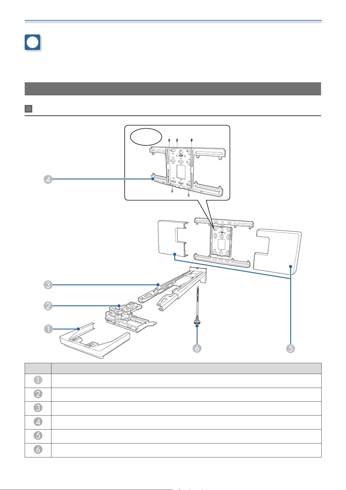
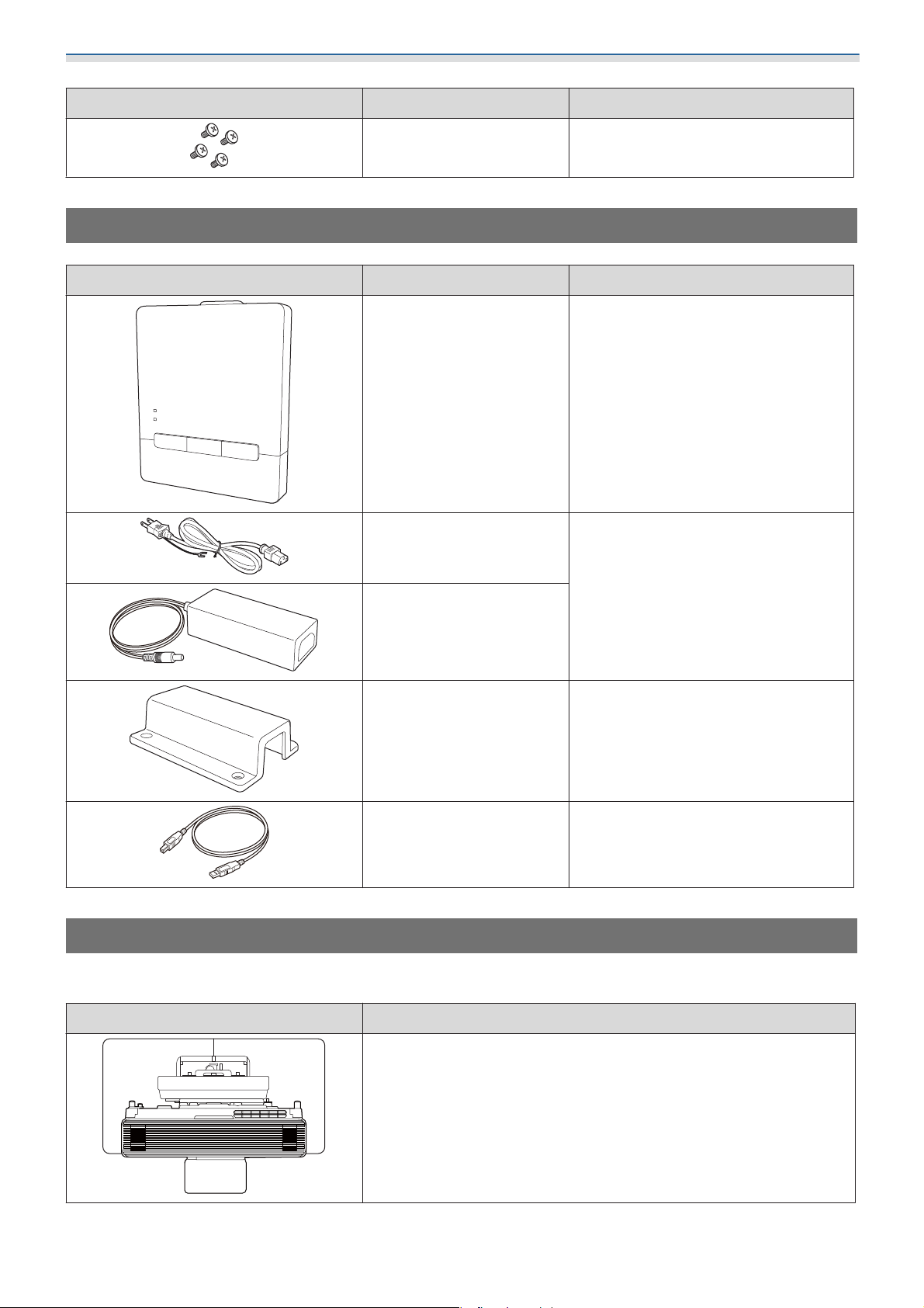
Wall Mount (Optional)
Main Mount
M4x12mm
No. Part name
End cap
Adjustment unit
Setting plate
Wall plate
Wall plate cover
Hexagonal axis
5
Page 7
Introduction
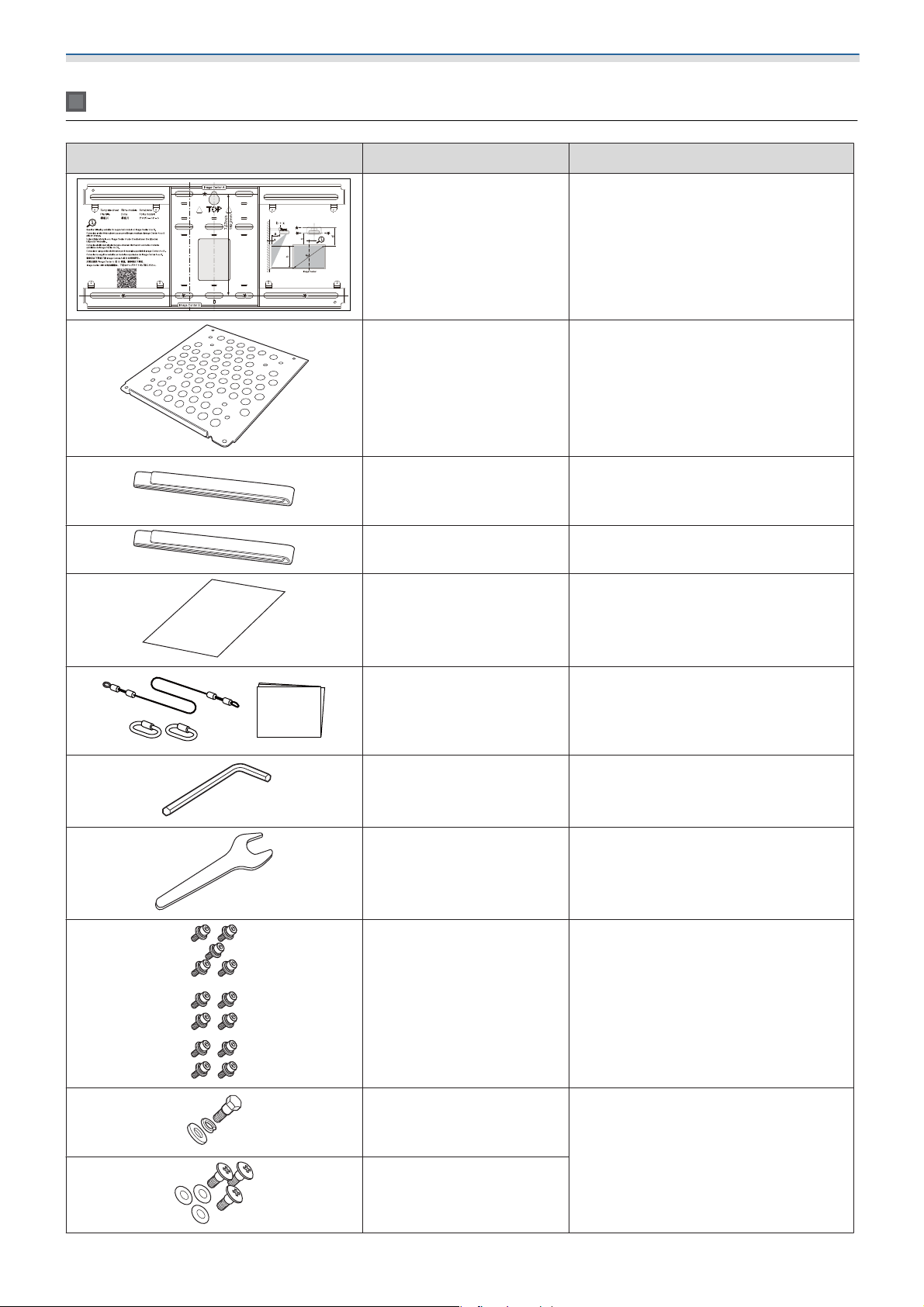
Accessories
Part Name Application
Template sheet Attach this to the wall before attaching
the wall plate, and use it to drill necessary holes.
Mini PC plate Attach this to the wall plate when in-
stalling a mini PC or stick PC.
Mini PC belt Secure the PC to the plate when at-
taching a mini PC or a stick PC that cannot be attached using screws.
Cable binding belt Secure excess cables after performing
wiring.
Masking sticker Stick this over the groove in the arm of
setting plate to cover it up after installing.
Safety wire set Connect to the wall mount and the
projector to prevent the projector from
falling. See the user's guide supplied
with the safety wire set for more details.
Hexagon wrench (for M4) -
Spanner (No. 13 for M6) -
M4 x 12 mm hexagon socket head cap bolt with washer/spring washer (x13)
•
Assemble the wall plate as shown in
the figure on p.5 (x5)
•
Secure the adjustment unit to the projector (x4)
•
Secure the adjustment unit to the setting plate (x4)
M6 x 20 mm hexagon
shoulder head bolt with
washer/spring washer (x1)
M6 x 20 mm cross recessed
head shoulder screws with
plastic washers (x3)
6
Secure the setting plate to the wall
plate.
Page 8
Introduction
Part Name Application
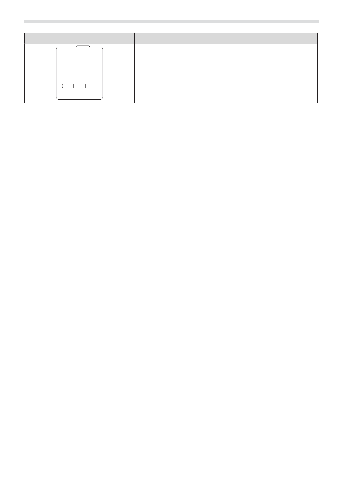
Control Pad (Optional)
Part Name Application
M3 x 6 mm cross recessed
head shoulder screws (x4)
Control Pad -
Power cable
(approx. 1.8 m)
Secure the mini PC plate to the wall
plate.
Power the Control Pad.
AC adapter
AC adapter holder Secure the AC adapter to the wall.
USB cable (approx. 1.8 m) Connects the Control Pad to the com-
puter.
Necessary Items
As well as the items supplied, you also need to prepare the following screws and tools.
Applicable parts Necessary items
For the wall mount
•
M10 or 3/8 inch x 60 mm anchor bolts (for securing the wall plate: at
least x4)
•
M10 screw (for securing the wall plate temporarily: x1)
•
17 mm ratchet wrench (for adjusting hexagonal axis)
•
Cables to connect to the projector
•
Devices such as mini PCs
7
Page 9
Introduction
Applicable parts Necessary items
For Control Pad
•
M4 x 20 mm screws (for securing control pad: 4)
8
Page 10
Introduction
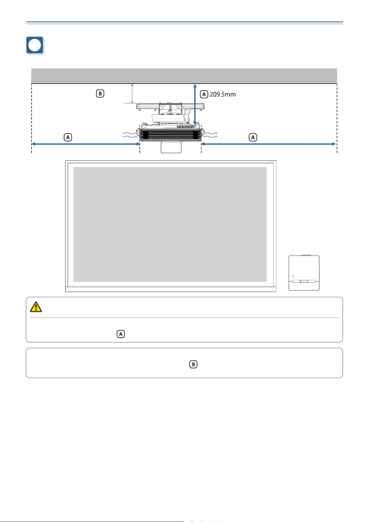
Figures of Installation Dimensions
100mm
500mm 500mm
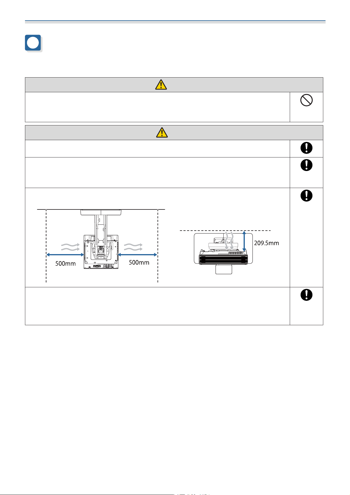
Caution
When installing the projector, make sure there is a gap between the wall and the projector's air exhaust
and intake vents. (See figure
Leaving a gap of approximately 100 mm from the ceiling to the top of the wall plate makes it easier
to install and remove the projector. (See figure
c
above)
above)
9
Page 11
Introduction
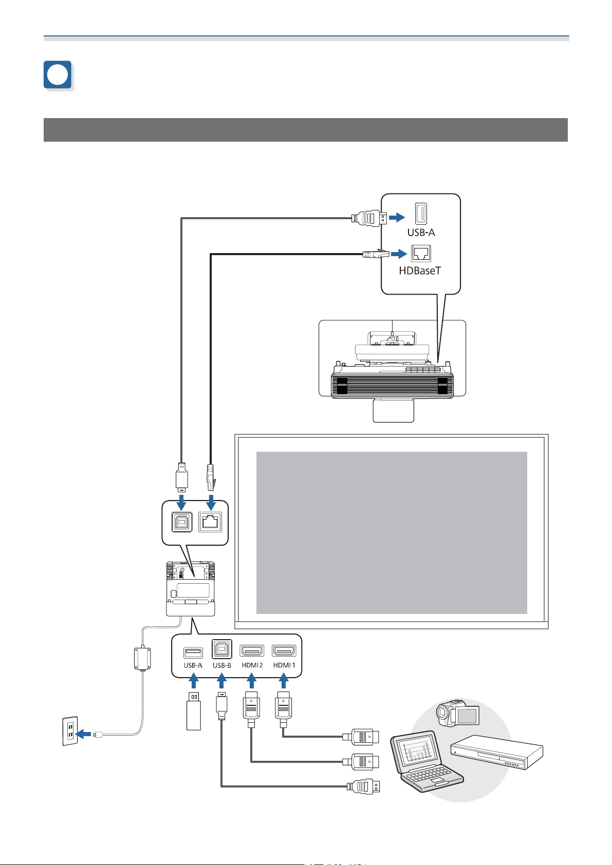
Connection Figure
Connecting the Control Pad
You need the following cables when using the Control Pad.
Prepare a commercially available LAN cable and USB cable to connect the projector and the Control Pad.
(4K30p:Max40m(CAT6a/CAT7))
(1080p60p:Max70m(CAT6a/CAT7))
10
Page 12
Introduction
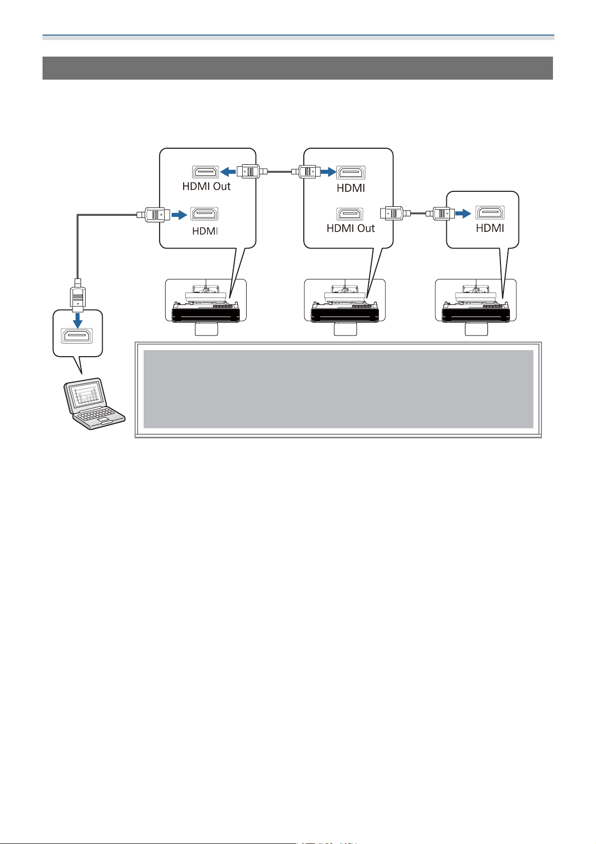
Connecting Multiple Projectors
You need the following cables when installing multiple projectors.
You can install two to four projectors side-by-side.
The following image is an example of connecting three projectors.
(Max 5m)
(Max 5m)
11
Page 13
Installing the Wall Mount
Cautions on Installing the Wall Mount
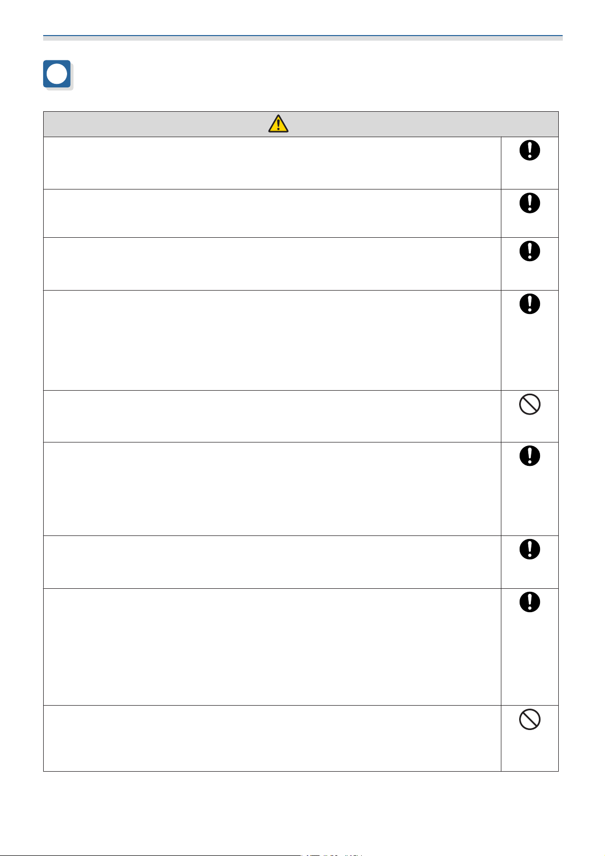
Warning
The Wall mount is exclusively for mounting the projector on a wall. If anything other than
a projector is mounted, the weight may result in damage.
If this product falls, it could cause death or personal injury.
The installation work (wall mounting) should be performed by specialists who have technical knowledge and ability. Incomplete or incorrect installation could cause the product
to fall and cause personal injury or property damage.
Follow the steps in this guide to install the Wall mount, and be sure to use the bolts and
screws specified in this guide.
If the instructions are not followed, this product may fall, resulting in personal injury or an accident.
Handle the power cord carefully.
Incorrect handling may cause fire or electric shock. Observe the following precautions when handling:
•
Do not handle the power plug with wet hands.
•
Do not use a power cord that is damaged or modified.
•
Do not pull the power cord with too much force when routing the cable through the setting plate.
Do not install the setting plate in a place where it might be subjected to vibration or shock.
This could cause damage to the projector or mounting surface. If this product falls, it could cause
death or personal injury.
When installing on a wall, install so that it can sufficiently support the mass of the projector
and the Wall mount and resist any horizontal vibration. Use M10 or 3/8 inch x 60 mm nuts
and bolts.
Nuts and bolts smaller than M10 or 3/8 inch x 60 mm could cause the setting plate to fall. Epson
accepts no responsibility for any damage or injury caused by lack of wall strength or inadequate
installation.
The installation work should be performed by at least two qualified service personnel. If
you need to loosen any screws during installation, be careful not to drop this product.
If this product falls, it could cause death or personal injury.
When installing this product on a wall, the wall requires enough strength to hold the projector and the Wall mount.
This product should be installed on a concrete wall.
The maximum combined weight of the projector and the Wall mount is approximately 18.9kg (not
including cables).
Ensure the strength of the wall before mounting this product on the wall. If the wall is not strong
enough, reinforce the wall before installation.
Inspect the setting plate on a regular basis to ensure there are no broken parts or loose
screws.
If any parts are damaged, stop using the setting plate immediately. If this product falls, it could
cause death or personal injury.
12
Page 14
Installing the Wall Mount
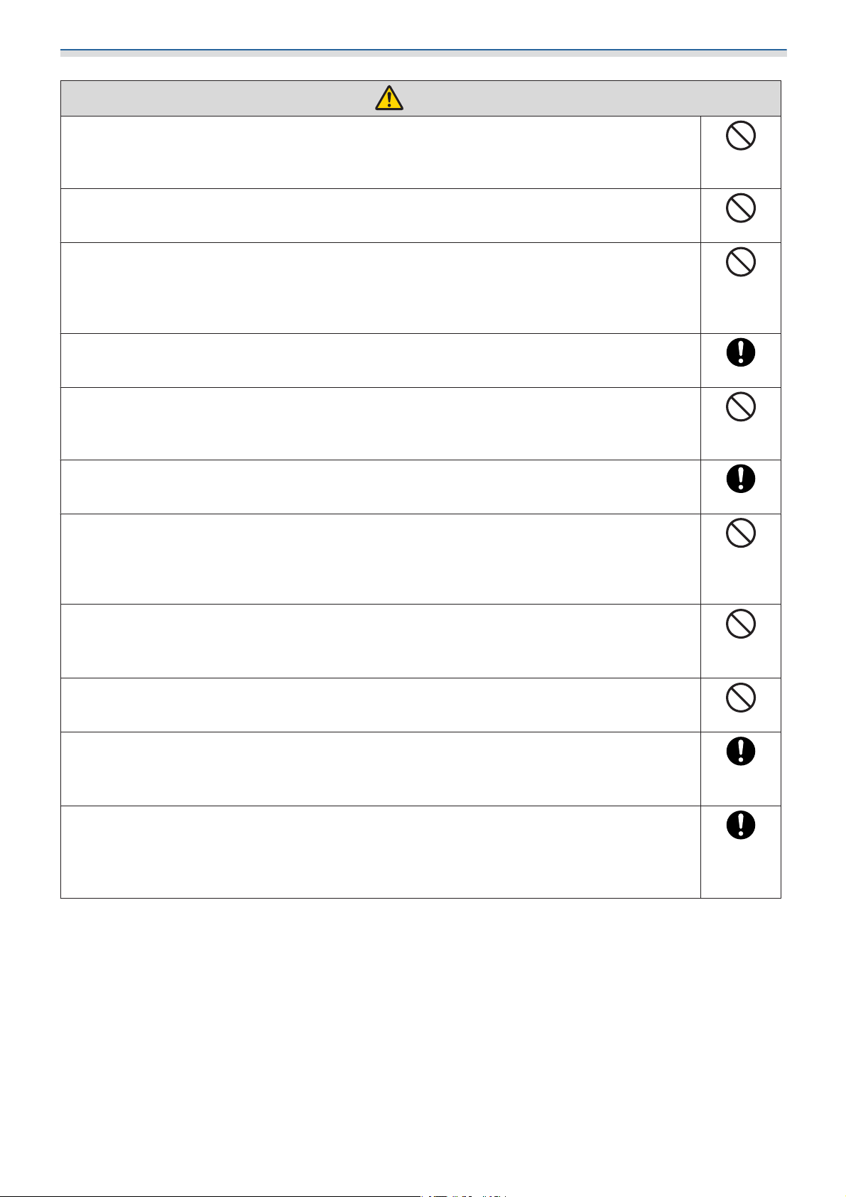
Warning
Do not disassemble or remodel this product.
There are numerous high-voltage sections inside the product that could cause a fire, electric shock,
or an accident.
Do not hang on this product. Do not hang heavy objects on this product.
If this product falls, it could cause death or personal injury.
Do not use adhesives, lubricants, or oils to install or adjust the Wall mount.
If you use adhesives to prevent the screws from loosening or things such as lubricants or oils on
the slide plate fixing part of the projector, the case may crack and cause the projector to fall,
resulting in personal injury or property damage.
Tighten all screws firmly after adjustment.
Otherwise, the product may fall and cause personal injury or property damage.
Never loosen the bolts and nuts after installation.
Confirm that the screws have not become loose on a regular basis. If you find any loose screws,
tighten them firmly. Otherwise, the product may fall an d ca us e pe rs on al i nj ur y or pr op ert y d ama ge .
Route the cables so that they are not interfered with the nuts and bolts.
Incorrect handling of the cables may cause fire or electric shock.
When turning on the projector, do not look into the projection lens.
This could cause damage to eyesight due to the powerful light emitted. Take particular care when
there are children present. When turning on the projector at a distance using the remote control,
make sure there is no one looking into the projection lens.
When using the projector, do not place any objects or put your hand near the projection
lens.
This area is dangerous as it reaches a high temperature due to the concentrated projection light.
Do not use the projector in a location subject to combustible or explosive gas.
High temperatures within the projector may cause ignition and a fire to occur.
Only a specialist should remove or reinstall the projector, including for maintenance and
repairs.
See the projector's User's Guide for instructions on maintenance and repairs.
If any abnormalities occur with this product, immediately disconnect the cables from the
product, and then contact your local dealer or the nearest Epson service call center.
Continuing to use the product in an abnormal condition could cause a fire, electric shock, or visual
impairment.
13
Page 15
Installing the Wall Mount
Warning
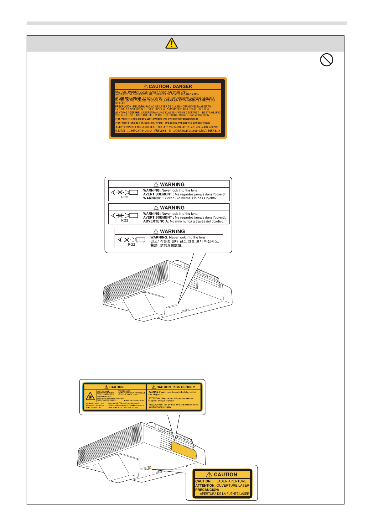
Laser warning labels have been attached to the inside and outside of the projector.
Internal
External
Do not look into the laser beam emitted from the projection lens while projecting. (Based on IEC/
EN60825-1:2014)
For North/South America
This projector is a Class 2 laser product that complies with the IEC/EN60825-1:2007 international
standard for lasers.
Complies with FDA performance standards for laser products except for deviations pursuant to
Laser Notice No. 50, dated June 24, 2007.
14
Page 16
Installing the Wall Mount
Warning
Never open any cases on the projector.
Electrical voltages inside the projector can cause severe injury.
Do not look directly into the projector’s light source.
Possibly hazardous optical radiation emitted from this product. Eye injury may result.
Caution
Do not install this product in a location where the operating temperature for your projector
model may be exceeded.
Such an environment may damage the projector.
Install this product in a place free from excessive dust and humidity to prevent the lens or
optical components from becoming dirty.
Do not use excessive force when adjusting this product.
This product may break, resulting in personal injury.
This projector is a Class 1 laser product that complies with the IEC/EN60825-1: 2014
international standard for lasers.
Do not disassemble the projector when disposing of it.
Dispose according to your local or national laws and regulations.
15
Page 17
Installing the Wall Mount
Cautions on the Installation Location of the Wall Mount
Warning
Do not install in a location subject to oily smoke or smoke for events.
If oils and so on stick to the slide plate fixing part of the projector, the case may crack and cause
the projector to fall, resulting in personal injury or property damage.
Caution
Carry out power supply wiring work at the installation location of the projector in advance.
Install the projector away from other electric devices such as fluorescent lights or air conditioners.
Some types of fluorescent lights could interfere with the remote control.
When installing the projector, make sure there is a gap between the wall and the projector's
air exhaust and intake vents as shown in the following image.
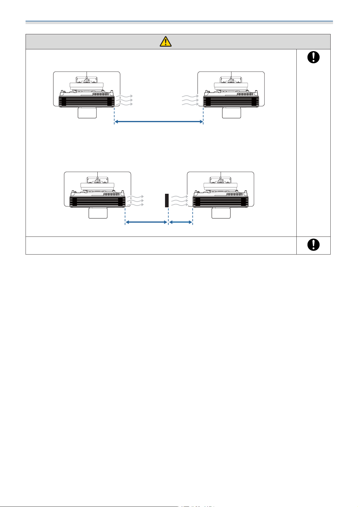
When installing two or more projectors in parallel, make sure the temperature of the surrounding environment is less than 35°C.
If the environment is too hot, the projector may overheat and the power may turn off without
warning.
16
Page 18
Installing the Wall Mount
Caution
When installing two or more projectors in parallel, leave a gap of at least 1,200 mm between
the projectors.
1200mm
If you cannot secure a gap of approx. 1,200 mm, install a partition to block the heat vented from
the projector's air exhaust vent.
The partitions should be larger than the exhaust vent (approx. 20 mm in all directions), and installed
approximately 400 mm from the exhaust vent and 200 mm from the intake vents.
400mm 200mm
We recommend using stick-on screens or board screens.
17
Page 19

Installing the Wall Mount
Wall Mount Specifications
Item Specification
Wall mount mass (setting plate, hexagonal axis, adjustment unit, wall plate,
wall plate cover, end cap)
Maximum load capacity Approx. 15.0 kg
Approx. 9.2 kg
18
Page 20
Installing the Wall Mount
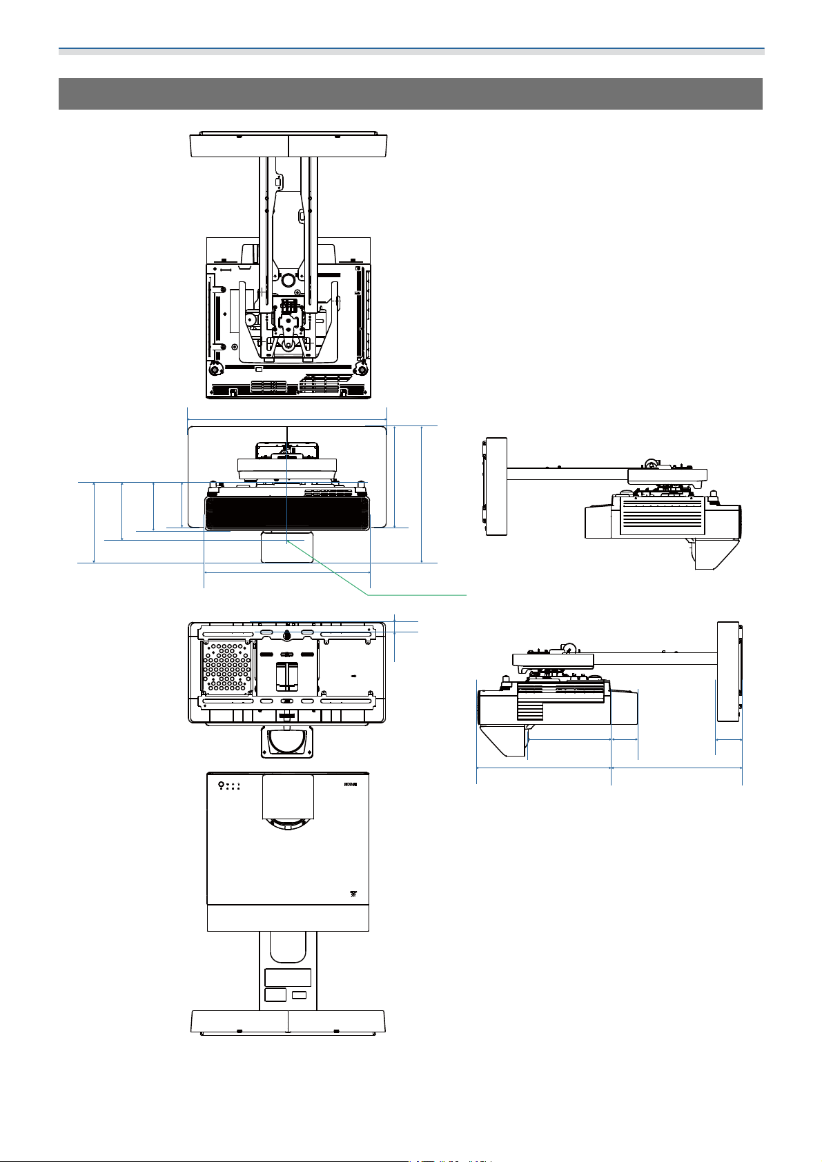
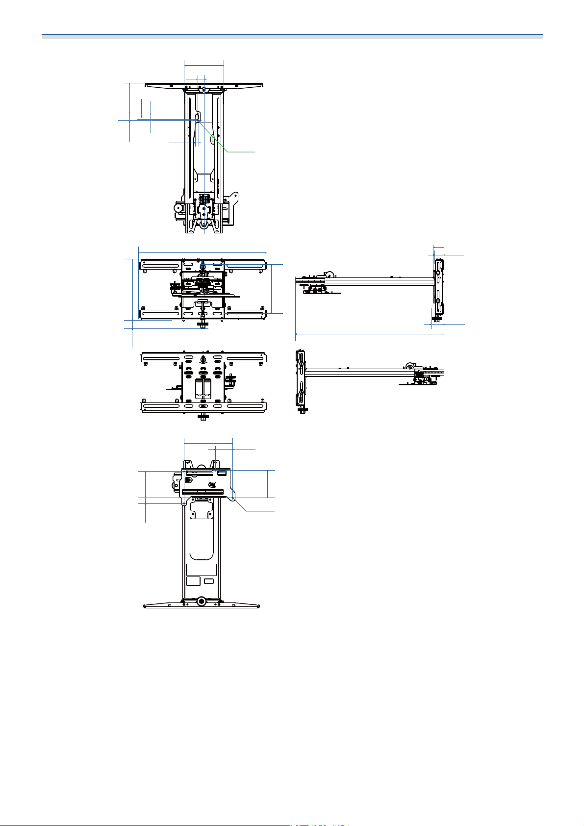
External Dimensions
550
223.5
160.8
134
125
458
28027.5
338.5-418.5
LENSCENTER
233
375 160-630
75
70
19
Page 21
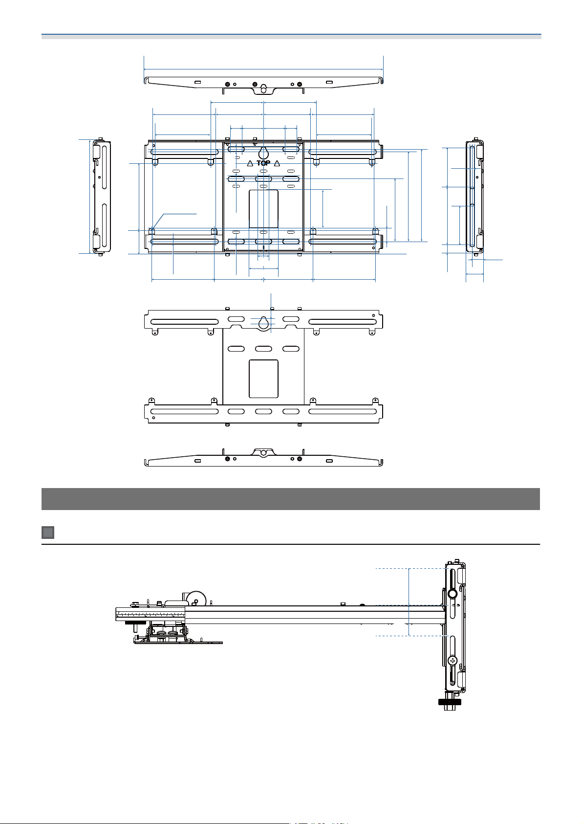
Installing the Wall Mount
125.9
5.3
20
30.5
162
26
12
2xM4
234.8
31.8
11225
496
208.5
41.1
35.7
192.2
48.2
891-508
74
117
4xM4
20
Page 22
Installing the Wall Mount
496
234.8
138.8
47.8
110
131
116
8xM4
10.2
130 130103 103
99
24
10.2
10.5
10.2
24
60
10.5
110
99
244545
79
131
116
28.3
130.2
186.4
192.2
81120.517.5
8.5
81
23.2
35.7
Adjustment Range
Vertical slide
40
40
21
Page 23

Installing the Wall Mount
Horizontal slide
45
Forward/backward slide
45
0-383
22
Page 24
Installing the Wall Mount
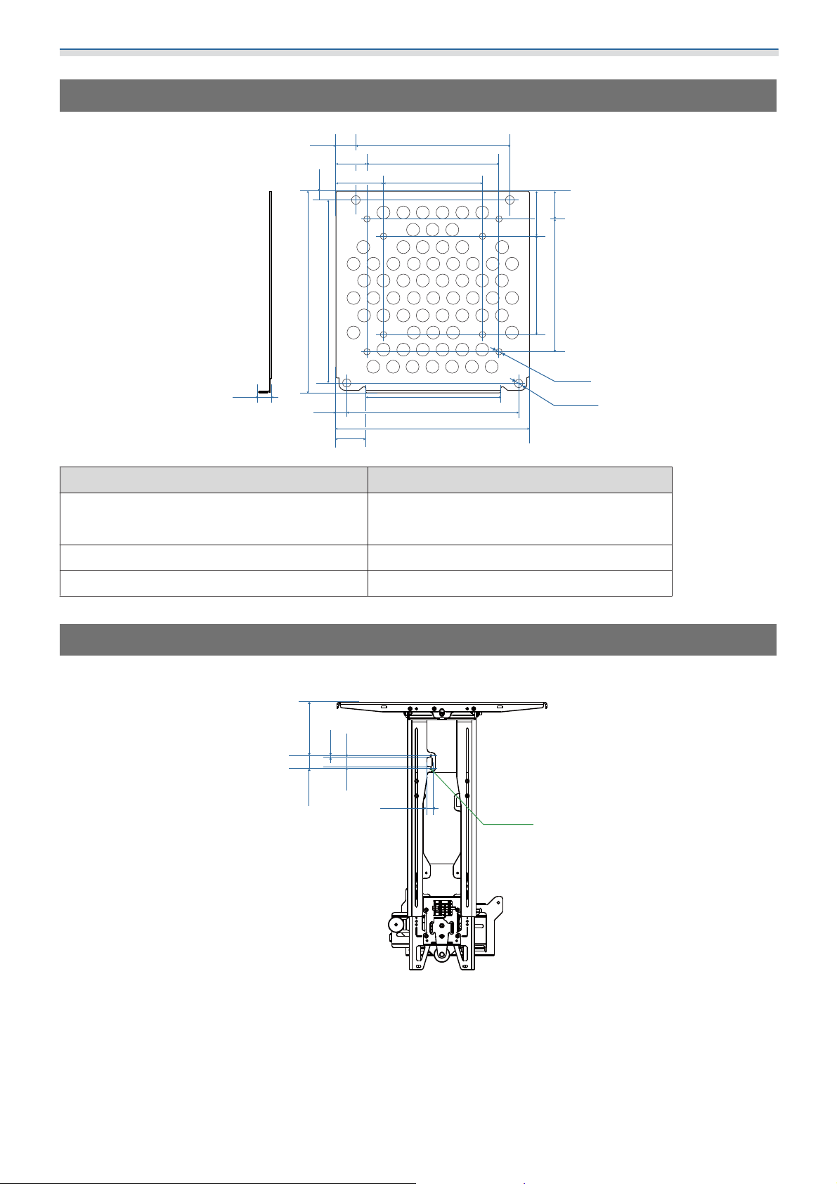
Mini PC Installation Plate
116
100
75
102
130
145.5
8.7
14.7
5.6
150.8
7.7
22.7
35.2
138.8
21.7
Item Specification
Screw holes for installing PC (VESA compliant) 75 mm x 75 mm
100 mm x 100 mm
32.7
75
8xΦ5
4xΦ3.8
10020.2
Supported PC sizes Within 150 mm x 150 mm x 44 mm
Supported PC weight 0.7 kg or less
Installing Accessories
When installing a switcher or a tuner, use the screw holes shown in the figure below to secure them.
125.9
5.3
20
30.5
12
2xM4
Before installing, check that the total weight, including the projector and connection cables, is below the
s
maximum load capacity for the Wall Mount. (
"Wall Mount Specifications" p.18)
23
Page 25
Installing the Wall Mount
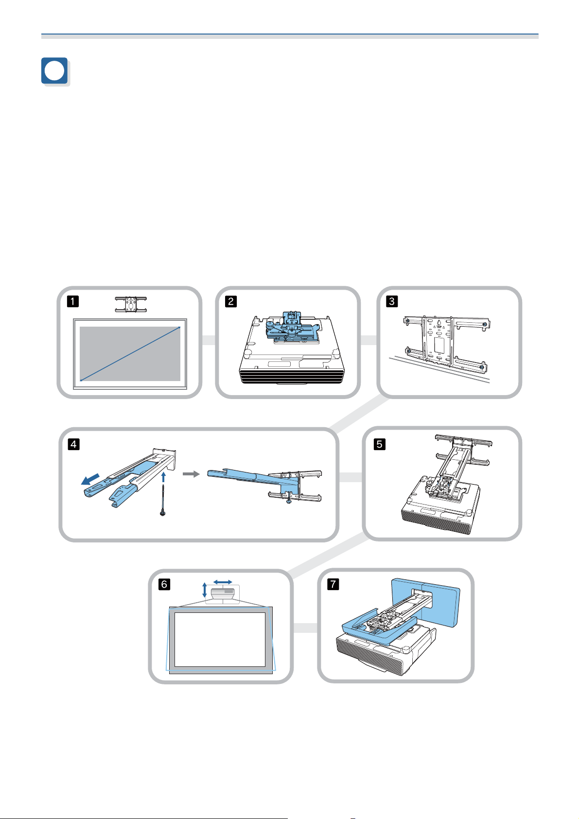
Installation Procedure for the Wall Mount
Follow the work flow below to install the wall mount.
Route the cables before installing the wall mount according to your installation environment.
Check the projection distance tables to determine the installation position (s p.25)
a
Attach the adjustment unit to the projector (s p.40)
b
Install the wall plate on the wall (s p.42)
c
Adjust the arm length of the setting plate, and then attach it to the wall plate (s p.44)
d
Attach the adjustment unit to the setting plate, and then connect the cables and peripheral devices
e
f
g
s
p.48)
(
Adjust the position of the image (s p.52)
Attach the covers (s p.65)
24
Page 26
Installing the Wall Mount
Attaching the Mount
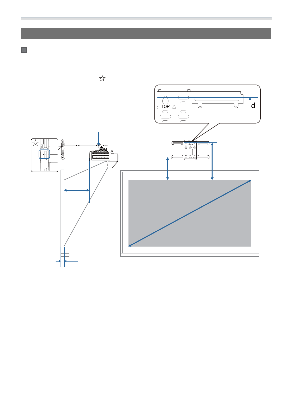
Determining the installation position (projection distance tables)
Determine the installation position of the wall plate according to the size of the screen (S) you want to project
on to. See the following figure to check the values from a to d. This is the value when the setting plate is in
the middle of the wall plate (See
in the following illustration).
b + x
a:
b + x:
x:
a
x
Minimum projection distance (Wide)
Number on the arm slide scale on the setting plate (Max. 533 mm)
Distance from the wall to the projection
surface
d
c
S
Distance from the top edge of the image
c:
to the installation screw hole for the wall
plate at the bottom
Distance from the top edge of the image
d:
to the temporary screw hole for the wall
plate
Projected image size
S:
25
Page 27
Installing the Wall Mount
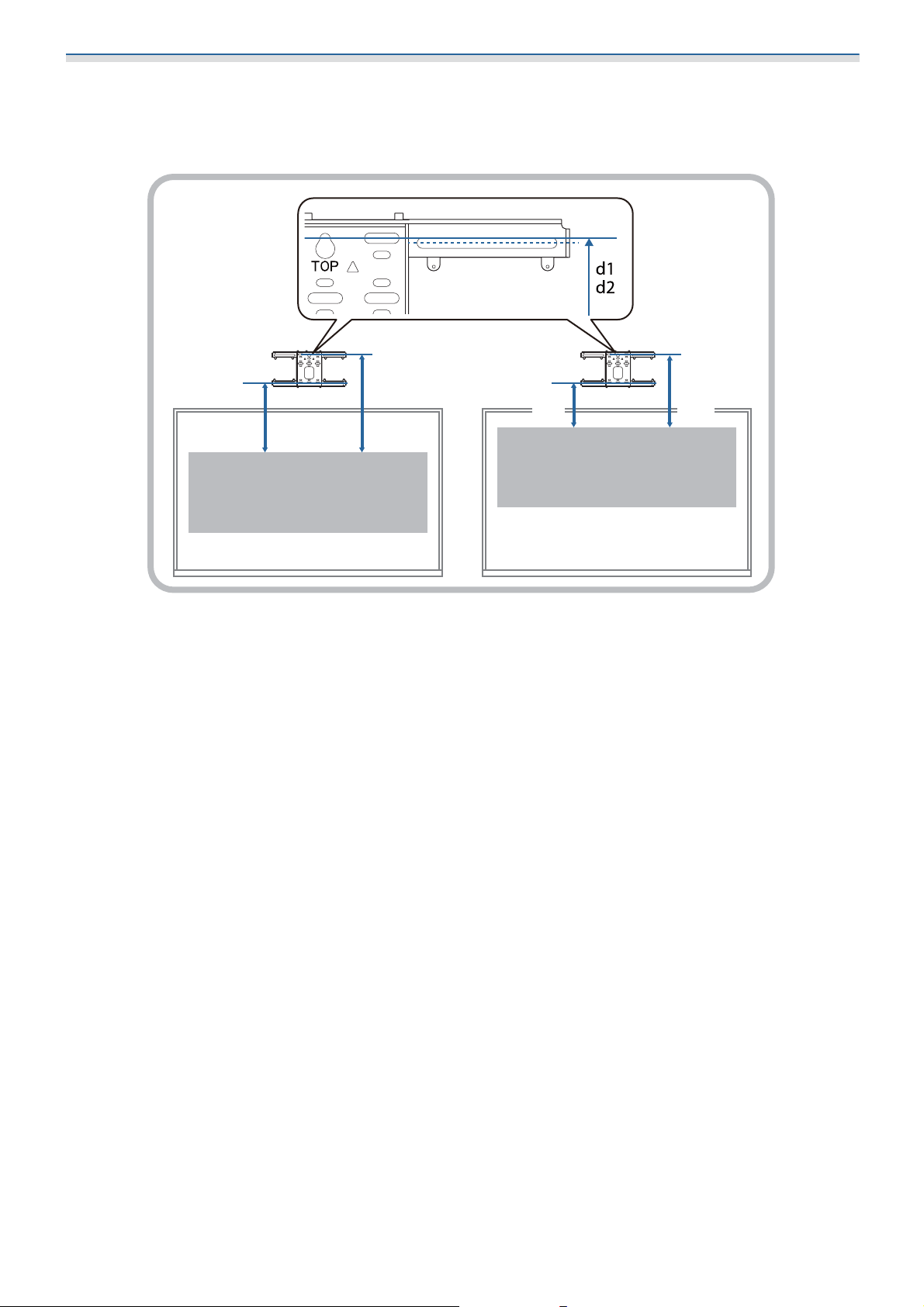
See the following for the values for c and d when projecting at an aspect ratio of 16:6 or 21:9.
•
c1/d1: When the Screen Position is in the center
•
c2/d2: When the Screen Position is at the top
c2 d2
c1 d1
26
Page 28
Installing the Wall Mount
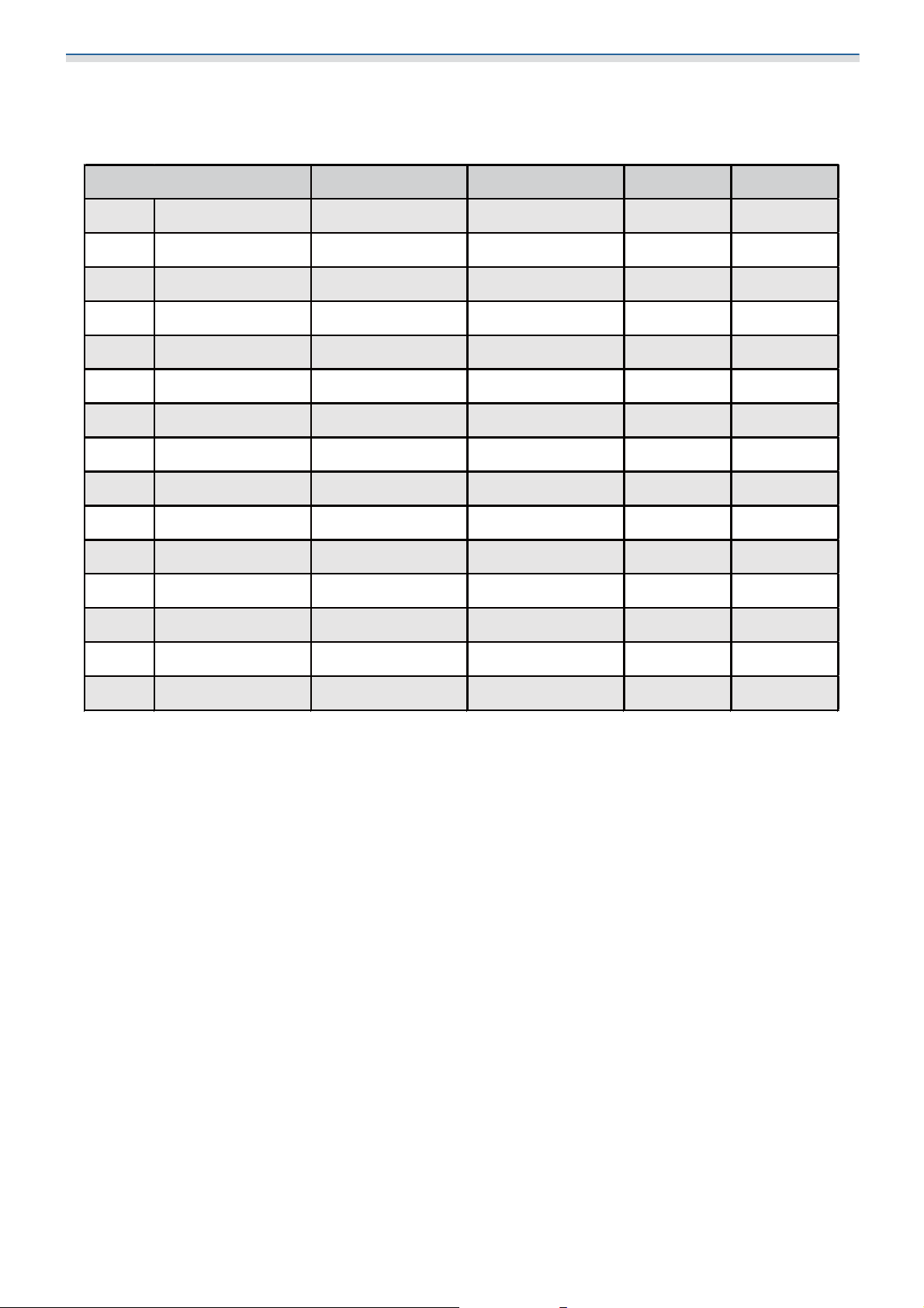
abcd
65" 1439 × 809 158 148 201 393
66" 1461 × 822 164 154 202 394
67" 1483 × 834 171 161 204 396
68" 1505 × 847 177 167 206 398
69" 1528 × 859 183 173 207 399
70" 1550 × 872 190 180 209 401
71" 1572 × 884 196 186 210 402
72" 1594 × 897 202 192 212 404
73" 1616 × 909 209 199 214 406
74" 1638 × 921 215 205 215 407
75" 1660 × 934 221 211 217 409
76" 1682 × 946 228 218 219 411
77" 1705 × 959 234 224 220 412
78" 1727 × 971 240 230 222 414
79" 1749 × 984 247 237 223 415
S
16:9 projected image
[Unit: mm]
27
Page 29
Installing the Wall Mount
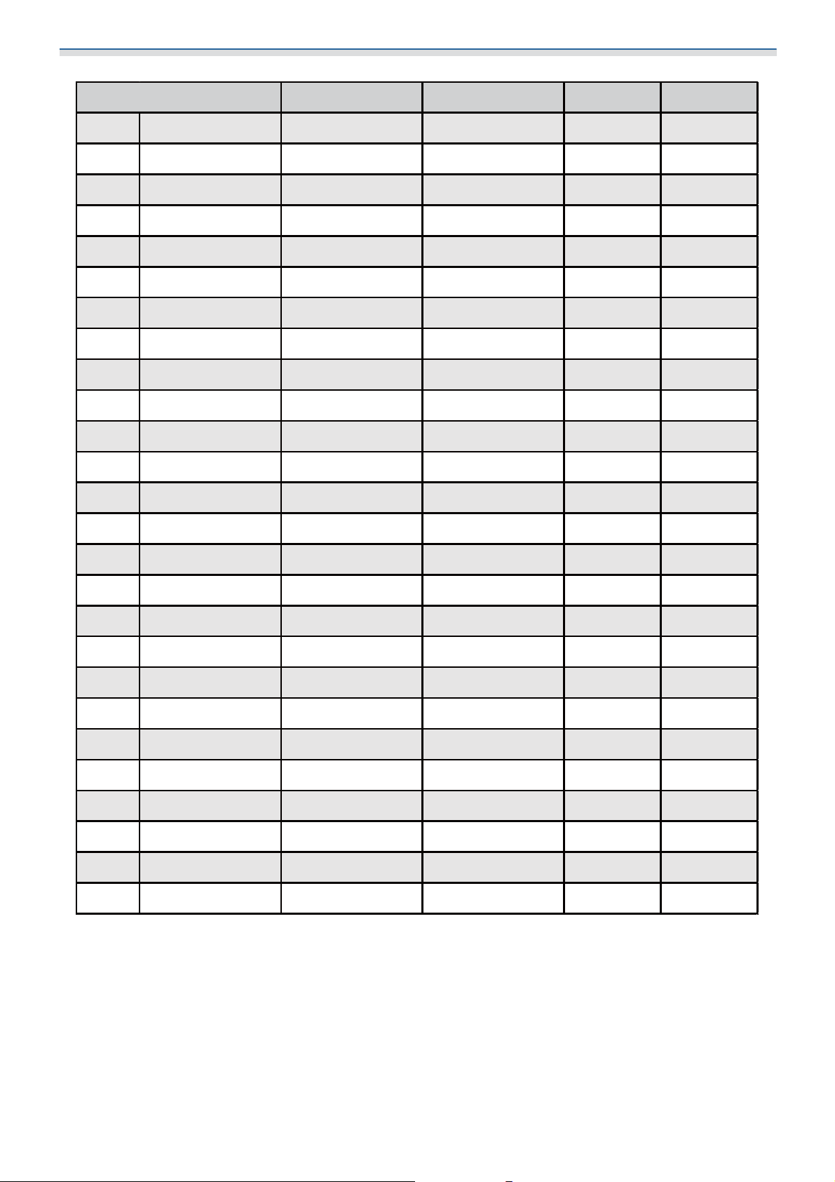
abcd
80" 1771 × 996 253 156 225 417
81" 1793 × 1009 259 162 227 419
82" 1815 × 1021 266 169 228 420
83" 1837 × 1034 272 175 230 422
84" 1860 × 1046 278 181 232 424
85" 1882 × 1058 285 188 233 425
86" 1904 × 1071 291 194 235 427
87" 1926 × 1083 297 200 236 428
88" 1948 × 1096 304 207 238 430
89" 1970 × 1108 310 213 240 432
90" 1992 × 1121 316 219 241 433
91" 2015 × 1133 323 226 243 435
92" 2037 × 1146 329 232 245 437
93" 2059 × 1158 335 238 246 438
94" 2081 × 1171 342 245 248 440
95" 2103 × 1183 348 251 249 441
96" 2125 × 1195 354 257 251 443
97" 2147 × 1208 361 264 253 445
98" 2170 × 1220 367 270 254 446
99" 2192 × 1233 373 276 256 448
100" 2214 × 1245 380 283 257 449
101" 2236 × 1258 386 289 259 451
102" 2258 × 1270 392 295 261 453
103" 2280 × 1283 399 302 262 454
104" 2302 × 1295 405 308 264 456
105" 2324 × 1308 411 314 266 458
S
28
Page 30

Installing the Wall Mount
abcd
106" 2347 × 1320 418 321 267 459
107" 2369 × 1332 424 327 269 461
108" 2391 × 1345 430 333 270 462
109" 2413 × 1357 437 340 272 464
110" 2435 × 1370 443 346 274 466
111" 2457 × 1382 449 352 275 467
112" 2479 × 1395 456 359 277 469
113" 2502 × 1407 462 365 279 471
114" 2524 × 1420 468 371 280 472
115" 2546 × 1432 475 378 282 474
116" 2568 × 1445 481 384 283 475
117" 2590 × 1457 487 390 285 477
118" 2612 × 1469 494 397 287 479
119" 2634 × 1482 500 403 288 480
120" 2657 × 1494 506 409 290 482
121" 2679 × 1507 513 416 292 484
122" 2701 × 1519 519 422 293 485
123" 2723 × 1532 525 428 295 487
124" 2745 × 1544 532 435 296 488
125" 2767 × 1557 538 441 298 490
126" 2789 × 1569 544 447 300 492
127" 2812 × 1581 551 454 301 493
128" 2834 × 1594 557 460 303 495
129" 2856 × 1606 563 466 305 497
130" 2878 × 1619 570 473 306 498
S
29
Page 31

Installing the Wall Mount
abcd
60" 1292 × 808 157 147 201 393
61" 1314 × 821 164 154 202 394
62" 1335 × 835 171 161 204 396
63" 1357 × 848 178 168 206 398
64" 1379 × 862 185 175 208 400
65" 1400 × 875 191 181 209 401
66" 1422 × 888 198 188 211 403
67" 1443 × 902 205 195 213 405
68" 1465 × 915 212 202 215 407
69" 1486 × 929 219 209 216 408
70" 1508 × 942 226 216 218 410
71" 1529 × 956 232 222 220 412
72" 1551 × 969 239 229 222 414
73" 1572 × 983 246 236 223 415
74" 1594 × 996 253 243 225 417
75" 1615 × 1010 260 250 227 419
76" 1637 × 1023 267 257 229 421
77" 1659 × 1037 274 264 230 422
78" 1680 × 1050 280 270 232 424
79" 1702 × 1063 287 277 234 426
S
16:10 projected image
[Unit: mm]
30
Page 32

Installing the Wall Mount
abcd
80" 1723 × 1077 294 197 236 428
81" 1745 × 1090 301 204 237 429
82" 1766 × 1104 308 211 239 431
83" 1788 × 1117 315 218 241 433
84" 1809 × 1131 321 224 243 435
85" 1831 × 1144 328 231 244 436
86" 1852 × 1158 335 238 246 438
87" 1874 × 1171 342 245 248 440
88" 1895 × 1185 349 252 250 442
89" 1917 × 1198 356 259 251 443
90" 1939 × 1212 363 266 253 445
91" 1960 × 1225 369 272 255 447
92" 1982 × 1239 376 279 257 449
93" 2003 × 1252 383 286 258 450
94" 2025 × 1265 390 293 260 452
95" 2046 × 1279 397 300 262 454
96" 2068 × 1292 404 307 264 456
97" 2089 × 1306 410 313 265 457
98" 2111 × 1319 417 320 267 459
99" 2132 × 1333 424 327 269 461
100" 2154 × 1346 431 334 271 463
S
31
Page 33

Installing the Wall Mount
abcd
101" 2175 × 1360 438 341 272 464
102" 2197 × 1373 445 348 274 466
103" 2219 × 1387 452 355 276 468
104" 2240 × 1400 458 361 278 470
105" 2262 × 1414 465 368 279 471
106" 2283 × 1427 472 375 281 473
107" 2305 × 1440 479 382 283 475
108" 2326 × 1454 486 389 285 477
109" 2348 × 1467 493 396 286 478
110" 2369 × 1481 499 402 288 480
111" 2391 × 1494 506 409 290 482
112" 2412 × 1508 513 416 292 484
113" 2434 × 1521 520 423 293 485
114" 2455 × 1535 527 430 295 487
115" 2477 × 1548 534 437 297 489
116" 2499 × 1562 541 444 299 491
117" 2520 × 1575 547 450 300 492
118" 2542 × 1589 554 457 302 494
119" 2563 × 1602 561 464 304 496
120" 2585 × 1615 568 471 306 498
S
32
Page 34

Installing the Wall Mount
abcd
53" 1077 × 808 157 147 201 393
54" 1097 × 823 165 155 202 394
55" 1118 × 838 173 163 204 396
56" 1138 × 853 180 170 206 398
57" 1158 × 869 188 178 208 400
58" 1179 × 884 196 186 210 402
59" 1199 × 899 204 194 212 404
60" 1219 × 914 211 201 214 406
61" 1240 × 930 219 209 216 408
62" 1260 × 945 227 217 218 410
63" 1280 × 960 235 225 220 412
64" 1300 × 975 242 232 222 414
65" 1321 × 991 250 240 224 416
66" 1341 × 1006 258 248 226 418
67" 1361 × 1021 266 256 228 420
68" 1382 × 1036 273 263 230 422
69" 1402 × 1052 281 271 232 424
70" 1422 × 1067 289 279 234 426
71" 1443 × 1082 297 287 236 428
72" 1463 × 1097 304 294 238 430
73" 1483 × 1113 312 302 240 432
74" 1504 × 1128 320 310 242 434
75" 1524 × 1143 328 318 244 436
76" 1544 × 1158 335 325 246 438
77" 1565 × 1173 343 333 248 440
78" 1585 × 1189 351 341 250 442
79" 1605 × 1204 359 349 252 444
80" 1626 × 1219 366 269 254 446
S
4:3 projected image
[Unit: mm]
33
Page 35

Installing the Wall Mount
abcd
81" 1646 × 1234 374 277 256 448
82" 1666 × 1250 382 285 258 450
83" 1687 × 1265 390 293 260 452
84" 1707 × 1280 397 300 262 454
85" 1727 × 1295 405 308 264 456
86" 1748 × 1311 413 316 266 458
87" 1768 × 1326 421 324 268 460
88" 1788 × 1341 428 331 270 462
89" 1808 × 1356 436 339 272 464
90" 1829 × 1372 444 347 274 466
91" 1849 × 1387 452 355 276 468
92" 1869 × 1402 459 362 278 470
93" 1890 × 1417 467 370 280 472
94" 1910 × 1433 475 378 282 474
95" 1930 × 1448 483 386 284 476
96" 1951 × 1463 490 393 286 478
97" 1971 × 1478 498 401 288 480
98" 1991 × 1494 506 409 290 482
99" 2012 × 1509 514 417 292 484
100" 2032 × 1524 521 424 294 486
101" 2052 × 1539 529 432 296 488
102" 2073 × 1554 537 440 298 490
103" 2093 × 1570 545 448 300 492
104" 2113 × 1585 552 455 302 494
105" 2134 × 1600 560 463 304 496
S
34
Page 36

Installing the Wall Mount
a b c1 d1 c2 d2
61" 1451 × 544 161 151 338 530 202 394
62" 1475 × 553 168 158 342 534 204 396
63" 1498 × 562 175 165 346 538 206 398
64" 1522 × 571 182 172 350 542 207 399
65" 1546 × 580 189 179 353 545 208 400
66" 1570 × 589 195 185 357 549 210 402
67" 1593 × 598 202 192 361 553 212 404
68" 1617 × 606 209 199 365 557 214 406
69" 1641 × 615 216 206 369 561 215 407
70" 1665 × 624 223 213 373 565 217 409
71" 1689 × 633 229 219 377 569 219 411
72" 1712 × 642 236 226 381 573 221 413
73" 1736 × 651 243 233 385 577 222 414
74" 1760 × 660 250 240 389 581 224 416
75" 1784 × 669 257 247 393 585 226 418
76" 1807 × 678 263 253 397 589 228 420
77" 1831 × 687 270 260 401 593 229 421
78" 1855 × 696 277 267 405 597 231 423
79" 1879 × 705 284 274 409 601 233 425
S
16:6 projected image
[Unit: mm]
35
Page 37

Installing the Wall Mount
a b c1 d1 c2 d2
80" 1903 × 713 291 194 413 605 235 427
81" 1926 × 722 297 200 417 609 237 429
82" 1950 × 731 304 207 421 613 238 430
83" 1974 × 740 311 214 425 617 240 432
84" 1998 × 749 318 221 429 621 242 434
85" 2022 × 758 325 228 433 625 244 436
86" 2045 × 767 331 234 437 629 245 437
87" 2069 × 776 338 241 441 633 247 439
88" 2093 × 785 345 248 445 637 249 441
89" 2117 × 794 352 255 449 641 251 443
90" 2140 × 803 359 262 453 645 252 444
91" 2164 × 812 365 268 457 649 254 446
92" 2188 × 821 372 275 461 653 256 448
93" 2212 × 829 379 282 465 657 258 450
94" 2236 × 838 386 289 469 661 260 452
95" 2259 × 847 393 296 473 665 261 453
96" 2283 × 856 400 303 477 669 263 455
97" 2307 × 865 406 309 481 673 265 457
98" 2331 × 874 413 316 485 677 267 459
99" 2354 × 883 420 323 489 681 268 460
S
36
Page 38

Installing the Wall Mount
a b c1 d1 c2 d2
100" 2378 × 892 427 330 492 684 269 461
101" 2402 × 901 434 337 496 688 271 463
102" 2426 × 910 440 343 500 692 273 465
103" 2450 × 919 447 350 504 696 274 466
104" 2473 × 928 454 357 508 700 276 468
105" 2497 × 936 461 364 512 704 278 470
106" 2521 × 945 468 371 516 708 280 472
107" 2545 × 954 474 377 520 712 282 474
108" 2569 × 963 481 384 524 716 283 475
109" 2592 × 972 488 391 528 720 285 477
110" 2616 × 981 495 398 532 724 287 479
111" 2640 × 990 502 405 536 728 289 481
112" 2664 × 999 508 411 540 732 290 482
113" 2687 × 1008 515 418 544 736 292 484
114" 2711 × 1017 522 425 548 740 294 486
115" 2735 × 1026 529 432 552 744 296 488
116" 2759 × 1035 536 439 556 748 297 489
117" 2783 × 1043 542 445 560 752 299 491
118" 2806 × 1052 549 452 564 756 301 493
119" 2830 × 1061 556 459 568 760 303 495
120" 2854 × 1070 563 466 572 764 305 497
S
37
Page 39

Installing the Wall Mount
a b c1 d1 c2 d2
62" 1447 × 620 160 150 298 490 201 393
63" 1471 × 630 167 157 302 494 204 396
64" 1494 × 640 174 164 305 497 205 397
65" 1518 × 650 181 171 308 500 206 398
66" 1541 × 660 187 177 311 503 208 400
67" 1564 × 670 194 184 315 507 210 402
68" 1588 × 680 201 191 318 510 212 404
69" 1611 × 690 207 197 321 513 213 405
70" 1634 × 700 214 204 324 516 215 407
71" 1658 × 710 221 211 328 520 217 409
72" 1681 × 720 227 217 331 523 219 411
73" 1704 × 730 234 224 334 526 220 412
74" 1728 × 740 241 231 338 530 222 414
75" 1751 × 750 247 237 341 533 224 416
76" 1774 × 760 254 244 344 536 225 417
77" 1798 × 770 261 251 347 539 227 419
78" 1821 × 780 267 257 351 543 229 421
79" 1844 × 790 274 264 354 546 231 423
S
21:9 projected image
[Unit: mm]
38
Page 40

Installing the Wall Mount
a b c1 d1 c2 d2
80" 1868 × 800 281 184 357 549 232 424
81" 1891 × 810 287 190 360 552 233 425
82" 1914 × 820 294 197 364 556 236 428
83" 1938 × 830 301 204 367 559 237 429
84" 1961 × 840 307 210 370 562 239 431
85" 1984 × 850 314 217 374 566 241 433
86" 2008 × 860 321 224 377 569 243 435
87" 2031 × 870 327 230 380 572 244 436
88" 2054 × 880 334 237 383 575 246 438
89" 2078 × 890 341 244 387 579 248 440
90" 2101 × 900 347 250 390 582 249 441
91" 2125 × 911 354 257 393 585 251 443
92" 2148 × 921 361 264 396 588 252 444
93" 2171 × 931 367 270 400 592 255 447
94" 2195 × 941 374 277 403 595 256 448
95" 2218 × 951 381 284 406 598 257 449
96" 2241 × 961 388 291 410 602 260 452
97" 2265 × 971 394 297 413 605 261 453
98" 2288 × 981 401 304 416 608 263 455
99" 2311 × 991 408 311 419 611 264 456
100" 2335 × 1001 414 317 423 615 267 459
S
39
Page 41

Installing the Wall Mount
a b c1 d1 c2 d2
101" 2358 × 1011 421 324 426 618 268 460
102" 2381 × 1021 428 331 429 621 269 461
103" 2405 × 1031 434 337 432 624 271 463
104" 2428 × 1041 441 344 436 628 273 465
105" 2451 × 1051 448 351 439 631 275 467
106" 2475 × 1061 454 357 442 634 276 468
107" 2498 × 1071 461 364 446 638 279 471
108" 2521 × 1081 468 371 449 641 280 472
109" 2545 × 1091 474 377 452 644 282 474
110" 2568 × 1101 481 384 455 647 283 475
111" 2591 × 1111 488 391 459 651 285 477
112" 2615 × 1121 494 397 462 654 287 479
113" 2638 × 1131 501 404 465 657 288 480
114" 2661 × 1141 508 411 468 660 290 482
115" 2685 × 1151 514 417 472 664 292 484
116" 2708 × 1161 521 424 475 667 294 486
117" 2732 × 1171 528 431 478 670 295 487
118" 2755 × 1181 534 437 482 674 297 489
119" 2778 × 1191 541 444 485 677 299 491
120" 2802 × 1201 548 451 488 680 300 492
121" 2825 × 1211 554 457 491 683 302 494
122" 2848 × 1221 561 464 495 687 304 496
123" 2872 × 1231 568 471 498 306 306 498
S
Attaching the adjustment unit to the projector
Loosen the screws (x2) and remove the cable cover from the projector
a
40
Page 42

Installing the Wall Mount
Loosen the M4 bolt on the adjustment unit, and then align the marks for each part
b
c
When the position is correct, tighten the M4 bolt.
Secure the adjustment unit to the base of the projector with the M4 x 12 mm bolts (x4)
supplied
41
Page 43

Installing the Wall Mount
Install the wall plate on the wall
Attach the template sheet to the wall
a
Attach the template sheet according to the installation position that you confirmed using the
projection distance table ( p.25).
Align the center position of the screen being projected with Image Center A on the Template sheet.
b
Drive a commercially available M10 screw into the position of the temporary screw hole
for the wall plate
Leave a gap of 6 mm or more between the wall and the screw head.
42
Page 44

Installing the Wall Mount
Determine the positions for the mounting holes for the wall plate
c
d
From the screw holes shown in the figure below, secure at least four points for optimum balance.
Drill the holes in the wall
Drill diameter: 10.5 mm (M10) or 10 mm (3/8 inches)
Pilot hole depth: 45 mm
Anchor hole depth: 40 mm
10.5mm(M10)
or
10mm(3/8inch)
45mm
e
f
g
Remove the template sheet
Place the wall plate on the temporary M10 screw that you installed in step 2
Use commercially available M10 or 3/8 inch x 60 mm anchor bolts to secure the wall plate
to the holes you drilled in step 4
43
Page 45

Installing the Wall Mount
Attaching the setting plate to the wall plate
Loosen the M4 x 12 mm bolts (x2) and extend the arm slide on the setting plate
a
Adjust the scale on the slider to the combined distance of the value for (b) confirmed in the projection
distance table ( p.25) and the thickness of the projection surface (x).
b
Insert the hexagonal axis into the setting plate
44
Page 46

Installing the Wall Mount
Route the necessary cables through the setting plate
c
Warning
Do not hang the rest of the cable over the setting plate. They could fall and cause an accident.
Make sure that cable ports for connecting to peripheral devices such as mini PCs are routed
c
so that they come out of the lower part of the setting plate and not through walls.
45
Page 47

Installing the Wall Mount
Attach the setting plate to the wall plate
d
Insert the hexagonal axis until the tip extends slightly out of the top of the wall plate and the other
end connects to the bottom of the wall plate.
Caution
Take care not to trap the cables between the setting plate and wall plate.
46
Page 48

Installing the Wall Mount
Temporarily secure the setting plate
e
Secure three points with the M6 screws supplied (x3).
f
Adjust the vertical slide with the open-ended spanner to align the marks on the wall plate
and the setting plate.
47
Page 49

Installing the Wall Mount
Tighten the M6 bolt (x1) to secure the setting plate in position
g
Attaching the adjustment unit to the setting plate
Check the installation position for the adjustment unit
a
The installation position is marked on the setting plate. Install at an appropriate position according to
the size of the screen you want to project on to.
•
When a projected image is smaller than 80 inches: Install the unit at the mark.
•
When a projected image is 80 inches or more: Install the unit at the mark.
48
Page 50

Installing the Wall Mount
Attach the adjustment unit to the setting plate with the M4 x 12 mm bolts (x4) supplied
b
Connect the cables to the projector
c
Attaching external tuners and accessories
Use commercially available M4 screws to secure external tuners and accessories to the screw holes as shown
in the following figure.
Connect the power cord last.
Attaching peripheral devices
Attaching a mini PC or stick PC
Attach the mini PC or stick PC to the mini PC plate, and secure it to the left or right side of the wall plate.
49
Page 51

Installing the Wall Mount
Attach it so that the air exhaust vents of the PC are not blocked.
c
We recommend installing the PC so that the air exhaust vents are at the top and the air intake vents
are at the bottom.
When securing with the mini PC belt
Wrap the belt around the mini PC plate
a
b
Secure the mini PC plate to the wall plate using the M3 x 6 mm screws (x4) supplied.
50
Page 52

Installing the Wall Mount
Place the PC on the lower edge of the mini PC plate, and secure it with the belt
c
When securing with screws
Depending on the shape of the mini PC and the orientation of the screw holes, the order in which parts are
installed differs. Be sure to check the installation instructions in advance.
Installation example
•
Secure the mini PC plate with the PC installed to the wall plate using the M3 x 6 mm screws (x4) supplied.
•
Secure the mini PC plate to the wall plate using the M3 x 6 mm screws (x4) supplied, and then install the PC.
51
Page 53

Installing the Wall Mount
Adjusting the Position of the Projected Image
You can use any of the following methods to adjust the position of the projected image.
When multiple projectors are installed in the same room, we recommend that you set projector IDs
to prevent remote control interference.
c
Turn on a projector and set the ID number for the projector in Multi-Projection > Projector ID.
When you want to operate a specific projector, hold down the [ID] button on the remote control
and press the button with the same number as the projector ID.
•
Adjusting using the Setting Plate Installation Guide ( p.54)
Manually adjust the position of the setting plate according to the guide screen displayed. This is useful when you
want to perform fine adjustments to the projection position while maintaining the image quality.
•
Adjusting using the projector menus ( p.58)
Select the area you want to adjust and manually correct the image. This is useful when you want to make fine
adjustments to the projection position after making mechanical adjustments using the guide screen.
52
Page 54

Installing the Wall Mount
Quick Corner Arc Correction Point Correction
•
Adjusting using the Blanking feature ( p.64)
This feature hides part of the image so that it does not extend beyond the edges of the screen.
•
Images are not stable immediately after turning on the projector. After starting projection, wait for at
c
least 30 minutes before adjusting the image.
•
When setting up multiple projectors using the batch setup function, perform the batch setup before
adjusting the projected image.
•
We recommend the mechanical position adjustment of the setting plate to adjust the image when
you want to maintain image quality.
Preparations before adjusting
Press the [ ] button on the remote control or the control panel to turn on the projector
a
Open the projector’s front cover, and then perform approximate focus adjustment using
b
the focus lever
53
Page 55

Installing the Wall Mount
Press the [Menu] button
c
d
Using the Remote Control Using the Control Panel
Select Screen Type from the Installation menu to set the aspect ratio of the projected
image
If necessary, set the projection position by using Screen Position from the Installation
e
f
Use the guidance screen to adjust the position of the image.
menu.
Change the aspect ratio if necessary
Project images from a connected device, and then press the [Aspect] button on the remote control.
Each time you press the button, you see the aspect name on the screen and the aspect ratio changes.
The aspect ratio does not change when no images are being projected from the connected
c
Performing mechanical adjustment using the Setting Plate Installation Guide
device.
54
Page 56

Installing the Wall Mount
Press the [Menu] button
a
b
Using the Remote Control Using the Control Panel
Select Setting Plate Installation Guide from the Installation menu
c
You see the guidance screen.
Turn the adjustment dial in the installation guide to adjust the horizontal roll
55
Page 57

Installing the Wall Mount
Loosen the M4 screw, and then turn the adjustment dial in the installation guide to
d
e
adjust the horizontal rotation
Turn the adjustment dial in the installation guide to adjust the vertical tilt
f
Loosen the M4 bolt, and then adjust the horizontal slide
56
Page 58

Installing the Wall Mount
Loosen the M4 bolts (x2), and then adjust the forward/backward slide
g
h
Loosen the M6 bolt, and then adjust the vertical slide
Re-tighten the screws and bolts that you loosened in steps 3 to 8
i
Warning
Tighten all bolts and screws firmly. Otherwise, the product may fall and cause personal injury or
property damage.
57
Page 59

Installing the Wall Mount
Adjust the focus of position A in the following figure
j
When you have finished making adjustments, press the [Esc] button on the remote control
k
Arc Correction
a
or the control panel to exit the guidance screen
Adjusting using the projector menus
•
You can save adjusted values in Memory from the Geometry Correction menu.
•
c
Before performing the adjustment, set the Screen Type and Screen Position settings first. If you change
the Screen Type or Screen Position after making corrections, the corrections will be reset.
Press the [Menu] button
Using the Remote Control Using the Control Panel
58
Page 60

Installing the Wall Mount
Select Geometry Correction from the Installation menu
b
Select Arc Correction
c
59
Page 61

Installing the Wall Mount
Select the side you want to correct and make adjustment
d
When you reach a range that cannot be adjusted, you see the message Cannot adjust any further.
displayed.
When you have finished making adjustments, press the [Esc] button on the remote control
e
Quick Corner
a
or the control panel to finish adjustment
Press the [Menu] button
Using the Remote Control Using the Control Panel
60
Page 62

Installing the Wall Mount
Select Geometry Correction from the Installation menu
b
Select Quick Corner
c
61
Page 63

Installing the Wall Mount
Select the side you want to correct and make adjustment
d
When you reach a range that cannot be adjusted, you see the message Cannot adjust any further.
displayed.
While adjusting the sides, press buttons [1], [3], [7], and [9] on the remote control to select the
c
When you have finished making adjustments, press the [Esc] button on the remote control
e
Point Correction
or the control panel to finish adjustment
Press the [Menu] button
a
side you want to adjust.
Using the Remote Control Using the Control Panel
62
Page 64

Installing the Wall Mount
Select Geometry Correction from the Installation menu
b
Select Point Correction
c
d
Select Point Correction and then select the number of grid
63
Page 65

Installing the Wall Mount
Select the points you want to correct and make adjustment
e
If it is hard to see the grid, use Pattern Color to change the color of the grid.
c
When you have finished making adjustments, press the [Esc] button on the remote control
f
a
or the control panel to finish adjustment
Adjusting using the Blanking feature
Press the [Menu] button
Using the Remote Control Using the Control Panel
64
Page 66

Installing the Wall Mount
Select Blanking from the Installation menu
b
Select an edge, and then adjust the amount you want to hide
c
When you have finished making adjustments, press the [Esc] button on the remote control
d
or the control panel to finish adjustment
Attaching the Covers
Attach the left wall plate cover
a
65
Page 67

Installing the Wall Mount
Attach the right wall plate cover
b
Fit the end cap to the setting plate
c
c
If you are concerned about the groove in the arm, stick the supplied masking sticker.
66
Page 68

Installing the Wall Mount
Attach the cable cover to the projector, and then secure it with the screws (x2)
d
Attaching a Security Cable
Perform one of the following security measures if necessary.
•
Install a commercially available theft-prevention wire lock
Pass the wire lock through the security cable installation points on the projector and the setting plate.
•
Install a security wire from Kensington
The security slot on this product is compatible with the Microsaver Security System manufactured by Kensington.
See the following for more details on the Microsaver Security System.
http://www.kensington.com/
67
Page 69

Installing the Control Pad
Notes on the Control Pad
Warning
Only connect to the EB-805F/EB-800F. Do not connect it to any other projectors or devices.
Doing so may damage the device.
Route the cables so that they are not interfered with the nuts and bolts.
Incorrect handling of the cables may cause fire or electric shock.
The power cable supplied is exclusively for the ELPHD02. Do not use it with other devices.
Do not use a power cable that is damaged.
Otherwise, it may cause fire or electric shock. If the power cable is damaged (if the core wire is
exposed, the wire is broken, and so on), contact your local dealer or Epson repair center.
When connecting the power cable to the control pad, only use the AC adapter that was
supplied.
Failure to do so may cause the product to malfunction, overheat, or emit smoke that could cause
a fire or electric shock to occur.
Do not use the AC adapter at a voltage other than the specified power supply voltage.
Failure to do so may cause the product to malfunction, overheat, or emit smoke that could cause
a fire or electric shock to occur.
Do not pull on the AC adapter's cable or place heavy items on the cable. Do not modify
the power cable.
Otherwise, it may cause fire or electric shock.
Do not apply strong force or shocks to the AC adapter such as stepping on it, dropping it,
or striking it.
This could cause damage. If the AC adapter is damaged, turn off the control pad, unplug the power
plug from the power outlet, and contact your local dealer. Continuing to use the product while it
is damaged could cause a fire or electric shock.
Do not handle/operate the control pad, AC adapter, or power plug with wet hands.
Failure to do so may cause a malfunction, a fire, or electric shock.
Handle the power plug carefully.
Incorrect handling may cause a malfunction or damage which could cause a fire or electric shock.
Observe the following precautions when handling:
•
Do not use multi-socket adapters.
•
Do not plug in the plug when there is foreign material such as dust stuck to it.
•
Make sure the power plug is fully inserted.
•
Do not handle the power plug with wet hands.
•
When unplugging the power plug, always grip t he plug its elf and pul l it out, do not pull on the power
cable.
When moving the control pad, make sure you off the power, disconnect the AC adapter,
and check that all the wiring has been disconnected.
68
Page 70

Installing the Control Pad
Warning
If any of the following problems occur, immediately turn off the power and unplug the AC
adapter and the power plug from the outlet. Next, contact your local dealer or the nearest
Epson service call center.
•
You notice smoke, strange odors, or strange sounds
•
Water or foreign material gets inside the control pad
•
The control pad was dropped or the case was damaged
Do not spill tea, coffee, juice or any other drinks on the AC adapter, or expose it to pesticides.
Failure to do so may cause a malfunction, a fire, or electric shock. If drinks or so on are spilled on
the AC adapter, turn off the power, unplug the AC adapter from the power outlet, and contact your
local dealer. Continuing to use it in this condition could cause a fire or an electric shock.
Do not install the AC adapter in a confined location or cover it with a cloth and so on except
for the AC adapter holder supplied.
Otherwise, the AC adapter may become hot and cause burns or unexpected accidents.
Do not wrap the power cable around the AC adapter.
Failure to do so may cause it to disconnect or overheat.
Do not disassemble or remodel the control pad.
Before cleaning, make sure you unplug the AC adapter and the power plug from the power
outlet and check that all of the wiring has been disconnected.
If it is not cleaned for a long time, dust may accumulate and cause a fire or electric shock.
Make sure you clean it regularly.
Caution
Do not disassemble the Control Pad when disposing of it.
Dispose according to your local or national laws and regulations.
In North America, interface cables that pass through walls require a flame resistant rating of CL2. Use interface
cables that comply with NFPA70 regulations. Use at least two screws to attach to wood.
This product is also designed for IT power distribution system with phase-to-phase voltage 230V.
69
Page 71

Installing the Control Pad
Supplier's DECLARATION of CONFORMITY
According to 47CFR, Part 2 and 15
Class B Personal Computers and Peripherals; and/or
CPU Boards and Power Supplies used with Class B Personal Computers
We: Epson America, Inc.
Located at: 3840 Kilroy Airport Way
Long Beach, CA 90806
Tel: 562-981-3840
Declare under sole responsibility that the product identified herein, complies with 47CFR Part 2 and 15 of the
FCC rules as a Class B digital device. Each product marketed, is identical to the representative unit tested and
found to be compliant with the standards. Records maintained continue to reflect the equipment being
produced can be expected to be within the variation accepted, due to quantity production and testing on a
statistical basis as required by 47CFR 2.906. Operation is subject to the following two conditions : (1) this
device may not cause harmful interference, and (2) this device must accept any interference received,
including interference that may cause undesired operation.
Trade Name: EPSON
Type of Product: HDBASET CONTROL BOX
Model: EAI destination: ELPHD02
Other destination: ---
FCC Compliance Statement
For United States Users
This device complies with part 15 of the FCC Rules. Operation is subject to the following two conditions: (1)
This device may not cause harmful interference, and (2) this device must accept any interference received,
including interference that may cause undesired operation.
This equipment has been tested and found to comply with the limits for a Class B digital device, pursuant to
Part 15 of the FCC Rules. These limits are designed to provide reasonable protection against harmful
interference in a residential installation. This equipment generates, uses, and can radiate radio frequency
energy and, if not installed and used in accordance with the instructions, may cause interference to radio
communications. However, there is no guarantee that interference will not occur in a particular installation.
If this equipment does cause interference to radio and television reception, which can be determined by
turning the equipment off and on, the user is encouraged to try to correct the interference by one or more
of the following measures.
•
Reorient or relocate the receiving antenna.
•
Increase the separation between the equipment and receiver.
•
Connect the equipment into an outlet on a circuit different from that to which the receiver is connected.
•
Consult the dealer or an experienced radio/TV technician for help.
WARNING
The connection of a non-shielded equipment interface cable to this equipment will invalidate the FCC
Certification or Declaration of this device and may cause interference levels which exceed the limits
established by the FCC for this equipment. It is the responsibility of the user to obtain and use a shielded
equipment interface cable with this device. If this equipment has more than one interface connector, do not
leave cables connected to unused interfaces. Changes or modifications not expressly approved by the
manufacturer could void the user's authority to operate the equipment.
70
Page 72

Installing the Control Pad
For Canadian Users
71
Page 73

Installing the Control Pad
Control Pad Specifications
Item Specification
Control pad mass Approx. 0.6kg
Power (AC adapter) 100 to 240 V AC +/- 10%, 50/60 Hz
Power 12 VDC 2.5 A 30 W
Electricity consumption during use 4.5 W
Operating temperature 0 to 40°C (no condensation)
Operating altitudes 0 to 3,048 m
External Dimensions
[Unit: mm]
198
36.5 174
201.8
29 116
39.5
95
17.5 40
42.821.5
4xM4
Cable Routing Holes
You can use either of the cable openings indicated in .
Route the power cable along the groove at the back of the Control Pad (
72
).
Page 74

Installing the Control Pad
73
Page 75

Installing the Control Pad
Installing the Control Pad
Installing the Control Pad
Place your finger in the hole at the top and remove the front cover.
a
b
Connect the power cable and route the cable down the back
74
Page 76

Installing the Control Pad
Check the installation position and secure with commercially available M4 screws (20 mm
c
x4)
d
Warning
•
When screwing, make sure they are not tilted at an angle to the installation surface.
•
Make sure that the Control Pad is secured properly.
•
Do not use double-sided tape or magnets to secure the Control Pad.
We recommend checking the operation of the Control Pad before securing with screws.
c
Secure the AC adapter to the wall using M4 screws (x4)
75
Page 77

Installing the Control Pad
Place the AC adapter in the holder and connect it to the power supply
e
Connect the cable that is connected to the projector to the Control Pad
f
See "Connecting the Control Pad" p.10 for details on connecting.
Attach the front cover
g
Enabling the Control Pad
a
Turn on the projector, and then press the [Menu] button
Using the Remote Control Using the Control Panel
76
Page 78

Installing the Control Pad
Select HDBaseT from the Signal I/O menu
b
Select Connect ELPHD02 to On
c
The Control Pad can now communicate with the projector. The Link indicator on the Control Pad turns
blue while communicating with the projector.
77
Page 79

Setting the Projector
Batch Setup Function
After making the projector's menu settings for one projector, you can copy the settings to other projectors
(batch setup function). The batch setup function is only for projectors with the same model number.
Use one of the following methods.
•
Setup using a USB flash drive.
•
Setup by connecting the computer and projector with a USB cable.
•
Make settings using Epson Projector Management.
This guide explains the USB flash drive and the USB cable methods.
For details on making settings using Epson Projector Management, see the Epson Projector Management
Operation Guide.
•
If you do not want to copy the following settings, set Batch Setup Range to Limited.
c
•
Password Protection
•
EDID from the Signal I/O menu
•
Network menu
•
Perform batch setup before adjusting the position of the projectors. The batch setup function copies
adjustment values for the projected image such as Geometry Correction. If batch setup is performed
after adjusting the position of the projectors, the adjustments you made may change.
•
By using the batch setup function, the registered User's Logo is copied to the other projectors. Do not
register confidential information as the User's Logo.
Caution
Performing batch setup is the customers responsibility. If batch setup fails due to an accident such as a
power failure, communication error, the customer is responsible for any repair costs incurred.
Setup Using a USB flash drive
This section explains how to perform batch setup using a USB flash drive.
•
Use a FAT format USB flash drive.
•
c
a
The batch setup function cannot be used by USB flash drives that incorporate security functions. Use
a USB flash drive that does not incorporate security functions.
•
The batch setup function cannot be used by USB card readers or USB hard disks.
Saving settings to the USB flash drive
Disconnect the power cord from the projector, and check that all of the projector's
indicators have turned off
78
Page 80

Setting the Projector
Connect the USB flash drive to the projector's USB-A port
b
c
•
Connect the USB flash drive directly to the projector. If the USB flash drive is connected to the
c
While holding down the [Esc] button on the remote control or the control panel, connect
the power cord to the projector
The Power indicator and the Status indicator turn blue, and the Laser indicator and the Temp indicator
turn orange.
When all of the projector's indicators turn on, release the [Esc] button.
projector through a USB hub, the settings may not be saved correctly.
•
Connect an empty USB flash drive. If the USB flash drive contains data other than the batch setup
file, the settings may not be saved correctly.
•
The file name for the batch setup file is PJCONFDATA.bin. If you need to change the file name,
add text after PJCONFDATA. If you change the PJCONFDATA section of the file name, the
projector may not be able to recognize the file correctly.
•
You can only use single-byte characters for the file name.
When all of the indicators start flashing, the batch setup file is being written.
Caution
•
Do not disconnect the power cord from the projector while the file is being written. If the power cord
is disconnected, the projector may not start correctly.
•
Do not disconnect the USB flash drive from the projector while the file is being written. If the USB flash
drive is disconnected, the projector may not start correctly.
When writing completes normally, the projector turns off, and only the Power indicator is lit blue.
When the power turns off, remove the USB flash drive.
Copying saved settings to other projectors
a
Disconnect the power cord from the projector, and check that all of the projector's
indicators have turned off
79
Page 81

Setting the Projector
Connect the USB flash drive containing the saved batch setup file to the projector's USB-A
b
port
Do not store any data except for the batch setup file on the USB flash drive. If the USB flash
c
While holding down the [Menu] button on the remote control or the control panel, connect
drive contains data other than the batch setup file, the settings may not be copied correctly.
c
the power cord to the projector
The Power indicator and the Status indicator turn blue, and the Laser indicator and the Temp indicator
turn orange.
When all of the projector's indicators turn on, release the [Menu] button. The indicators turn on for
approximately 75 seconds.
When all of the indicators start flashing, the settings are being written.
Caution
•
Do not disconnect the power cord from the projector while the settings are being written. If the power
cord is disconnected, the projector may not start correctly.
•
Do not disconnect the USB flash drive from the projector while the settings are being written. If the
USB flash drive is disconnected, the projector may not start correctly.
When writing completes normally, the projector turns off, and only the Power indicator is lit blue.
When the power turns off, remove the USB flash drive.
Setup by Connecting the Computer and Projector with a USB Cable
The following operating systems support the batch setup function.
c
•
Windows 7 and later
•
OS X 10.11 and later
Saving settings to a computer
Disconnect the power cord from the projector, and check that all of the projector's
a
indicators have turned off
80
Page 82

Setting the Projector
Connect the computer's USB port to the projector's USB-B port with a USB cable
b
While holding down the [Esc] button on the remote control or the control panel, connect
c
the power cord to the projector
The Power indicator and the Status indicator turn blue, and the Laser indicator and the Temp indicator
turn orange.
When all of the projector's indicators turn on, release the [Esc] button.
The projector is recognized as a removable disk by the computer.
Open the removable disk, and save the batch setup file (PJCONFDATA.bin) to the computer
d
If you need to change the name of the batch setup file, add text after PJCONFDATA. If you
c
Perform "Remove USB device" on your computer, and then disconnect the USB cable
change the PJCONFDATA section of the file name, the projector may not be able to recognize
the file correctly. You can only use single-byte characters for the file name.
e
When using a Mac, perform "Remove EPSON_PJ".
c
The projector turns off and only the Power indicator is lit blue.
Copying saved settings to other projectors
a
b
Disconnect the power cord from the projector, and check that all of the projector's
indicators have turned off
Connect the computer's USB port to the projector's USB-B port with a USB cable
81
Page 83

Setting the Projector
While holding down the [Menu] button on the remote control or the control panel, connect
c
d
the power cord to the projector
The Power indicator and the Status indicator turn blue, and the Laser indicator and the Temp indicator
turn orange.
When all of the projector's indicators turn on, release the [Menu] button.
The projector is recognized as a removable disk by the computer.
Copy the batch setup file (PJCONFDATA.bin) that you saved to your computer to the toplevel folder of the removable disk
e
Do not copy any files or folders other than the batch setup file to the removable disk.
c
Perform "Remove USB device" on your computer, and then disconnect the USB cable
When using a Mac, perform "Remove EPSON_PJ".
c
When all of the indicators start flashing, the settings are being written.
Caution
Do not disconnect the power cord from the projector while the settings are being written. If the
power cord is disconnected, the projector may not start correctly.
When writing completes normally, the projector turns off, and only the Power indicator is lit blue.
82
Page 84

Setting the Projector
When Setup Fails
Check Remedy
Are the Laser and the Temp indicators
flashing orange quickly?
Are the Power and the Status indicators
blue, and the Laser and the Temp indicators flashing orange quickly?
The batch setup file may be corrupt, or the USB flash drive or USB
cable may not be connected correctly. Disconnect the USB flash
drive or the USB cable, unplug and then plug in the projector's
power cord, and then try again.
Writing the settings may have failed and an error may have occurred
in the projector's firmware. Stop using the projector, remove the
power plug from the electrical outlet, and contact Epson for help.
83
Page 85

Setting the Projector
Installing Multiple Projectors (MultiProjection)
You can create one horizontally long screen as a unified image projected from multiple projectors.
When performing multi-projection, make connections and the necessary settings in the following order.
When setting Multi-Projection, we recommend setting Operation > Sleep Mode to Off from the
projector’s Menu.
c
Connecting cables (s p.11)
a
Setting the Projector ID (s p.84)
b
Multi-Projection connection settings (s p.86)
c
HDMI Link settings (s p.87)
d
Multi-Projection image adjustment (s p.88)
e
Setting the Projector ID
Turn on the projector, and then press the [Menu] button
a
Using the Remote Control Using the Control Panel
84
Page 86

Setting the Projector
Select Projector ID from the Multi-Projection menu
b
Select the ID number for the projector
c
d
e
Press the [Esc] button to close the menu
Repeat steps 1 to 4 for the remaining projectors.
Point the remote control at the projector you want to operate, and then press the [ID]
button
The current ID number is displayed on the projection screen.
85
Page 87

Setting the Projector
While holding down the [ID] button, press the button with the same number as the
f
projector ID for the projector you want to operate
Remote control operations for the projector with the selected ID are enabled.
•
When Projector ID is set to Off, you can operate the projector using the remote control
c
regardless of the ID setting selected using the remote control.
•
When the remote control ID is set to 0, you can operate all of the projectors regardless of the
projector ID setting.
•
Operating multiple remote controls at the same time can cause accidental operations due to
infrared interference.
Multi-Projection Connection Settings
Make the following settings on all connected projectors.
Press the [Menu] button
a
Using the Remote Control Using the Control Panel
Select HDMI Out Setting from the Multi-Projection menu
b
86
Page 88

Setting the Projector
Select Pass Through
c
Follow the on-screen instructions to restart the projector.
Set the Number of Projectors
d
e
Set the number of connected projectors.
Set the order
Set the projector position for the projector on the far left to 1.
HDMI Link Settings
Use HDMI Link to link the power on/off function across multiple projectors.
Press the [Menu] button
a
Using the Remote Control Using the Control Panel
87
Page 89

Setting the Projector
Select HDMI Link from the Signal I/O
b
Select HDMI Link
c
d
e
Select On
Set Power On Link and Power Off Link according to the operations that you want to link
Adjusting the Image in Multi-Projection
Images are not stable immediately after turning on the projector. After starting projection, wait for
at least 30 minutes before adjusting the image.
c
Turn on the projector
a
88
Page 90

Setting the Projector
Press the [Color Mode] button on the remote control, and then set the Color Mode to Multi-
b
c
d
Projection
Press the [Menu] button
Using the Remote Control Using the Control Panel
Make necessary settings on the Multi-Projection menu
For details on making settings, see the projector's User's Guide.
Edge Blending
Black Level
Scale
Light Source Mode Adjust the brightness of the entire image. Select Cus-
Color Uniformity
Color Matching
RGBCMY
Adjust the image overlapping section to create a seamless image.
Set the magnification and splicing position for the image.
tom, and then adjust the Brightness Level based on the
darkest projector.
Adjust the color of the image for each projector so that
the entire image looks uniform.
89
Page 91

Appendix
List of Safety Symbols
The following table lists the meaning of the safety symbols labeled on the equipment.
Symbol mark Approved stand-
ards
IEC60417
No.5007
IEC60417
No.5008
IEC60417
No.5009
ISO7000
No.0434B
IEC3864-B3.1
IEC60417
No.5041
IEC60417
No.6042
ISO3864-B3.6
Meaning
Power On
To indicate connection to the mains.
Power Off
To indicate disconnection from the mains.
Standby
To identify the switch or switch position by means of which part
of the equipment is switched on in order to bring it into the
standby condition.
Caution
To identify general caution when using the product.
Caution, hot surface
To indicate that the marked item can be hot and should not be
touched without taking care.
Caution, risk of electric shock
To identify equipment that presents a risk of electric shock.
IEC60417
No.5957
IEC60417
No.5926
---
IEC60417
No.5001B
IEC60417
No.5002
---
IEC60417
No.5019
IEC60417
No.5017
For indoor use only
To identify electrical equipment designed primarily for indoor
use.
Polarity of d.c. power connector
To identify the positive and negative connections (the polarity)
on a piece of equipment to which a d.c. power supply may be
connected.
Battery, general
On battery powered equipment. To identify a device for instance
a cover for the battery compartment, or the connector terminals.
Positioning of battery
To identify the battery holder itself and to identify the positioning
of the batteries inside the battery holder.
Protective earth
To identify any terminal which is intended for connection to an
external conductor for protection against electric shock in case
of a fault, or the terminal of a protective earth electrode.
Earth
To identify an earth (ground) terminal in cases where the
not explicitly required.
is
90
Page 92

Appendix
Symbol mark Approved stand-
ards
IEC60417
No.5032
IEC60417
No.5031
IEC60417
No.5172
ISO 3864 General prohibition
ISO 3864 Contact prohibition
--- Never look into the projection lens while the projector is on.
Meaning
Alternating current
To indicate that the equipment is suitable for alternating current
only; to identify relevant terminals.
Direct current
To indicate that the equipment is suitable for direct current only;
to identify relevant terminals.
Class II equipment
To identify equipment meeting the safety requ irements specified
for Class II equipment according to IEC 61140.
To identify actions or operations that are prohibited.
To indicate injury that could occur due to touching a specific part
of the equipment.
--- To indicate that you must never place anything on the projector.
ISO3864
IEC60825-1
ISO 3864 Disassembly prohibition
IEC60417
No.5266
ISO3864
IEC60417
No.5057
IEC 60417-6056 Caution, movable fan blades
IEC 60417-6043 Caution, sharp corners
Caution, laser radiation
To indicate the equipment has a laser radiation part.
To indicate a risk of injury, such as electric shock, if the equipment
is disassembled.
Standby, partial standby
To indicate that part of the equipment is in the ready status.
Caution, movable parts
To indicate that you must keep away from movable parts according to protection standards.
To ind ica te tha t yo u must kee p away fro m th e blad es o f the m ovable fan according to protection standards.
To indicate that you must not touch the sharp corners of the
product according to protection standards.
-- Never look into the projection lens while the projector is on.
ISO7010
No. W027
ISO 3864
IEC60417
No.5109
Warning, light emission (UV, visible light, IR and so on)
To indicate that you must be careful not to injure your eyes or
skin when near light emitting sections.
Not to be used in residential areas
To indicate that the electrical equipment/device is not suitable
for use in a residential area.
91
Page 93

Appendix
Indication of the manufacturer and the importer in accordance with requirements of directive 2011/65/
EU (RoHS)
Manufacturer: SEIKO EPSON CORPORATION
Address: 3-5, Owa 3-chome, Suwa-shi, Nagano-ken 392-8502 Japan
Telephone: 81-266-52-3131
http://www.epson.com/
Importer: SEIKO EUROPE B.V.
Address: Azië building, Atlas ArenA, Hoogoorddreef 5, 1101 BA Amsterdam Zuidoost The Netherlands
Telephone: 31-20-314-5000
http://www.epson.eu/
92
Page 94

Appendix
General Notice
Mac and OS X are trademarks of Apple Inc.
Microsoft and Windows are trademarks or registered trademarks of Microsoft Corporation in the United States
and/or other countries.
© 2020 Seiko Epson Corporation
2020.05 413961800ENPDFS
93
 Loading...