

Page 1
EPSONTERMINALPRINTER
StylusTMCOLOR IIs&StylusTM820
SERVICEMANUAL
EPSON
4005245
Page 2

NOTICE
All rights reserved. Reproduction of any part of this manual in any form whatsoever without SEIKO
EPSON’s express written permission is forbidden.
The contents of this manual are subjects to change without notice.
All efforts have been made to ensure the accuracy of the contents of this manual. However, should any errors
be detected, SEIKO EPSON would greatly appreciate being informed of them.
The above notwithstanding SEIKO EPSON can assume no resoinsibility for any errors in this manual or the
consequence thereof.
Epson and Epson’s ESC/P are registered trademark of Seiko Epson Corporation.
General Notice: Other product names used herein are for identication purpose only and may be trademark of
their respective companies.
+ Copyright 1995 by SEIKO EPSON CORPORATION Nagano, Japan
-i-
Page 3

PRECAUTIONS
Precautionary notations throughout the text are categorized relative to 1) personal jnjuury and 2) damage to
equipment.
DANGER Signals a precaution which, if ignored, could result in serious or fatal personal injury.
Great caution should be exercised in performing procedures preceded by DANGER
Headings.
WARNING Signals a precaution which, if ignored, could result in damage to equipment.
The precautionary measures itemized below should always be observed when performing repair/
maintenance procedures.
DANGER
1. ALWAYS DISCONNECT THE PRODUCT FROM THE POWER SOURCE AND PERIPHERAL
DEVICES PERFORMING ANY MAINTENANCE OR REPAIR PROCEDURE.
2. NOWORK SHOULD BE PERFORMED ON THE UNIT BY PERSONS UNFAMILIAR WITH
BASIC SAFETY MEASURES AS DICTATED FOR ALL ELECTRONICS TECHNICIANS IN
THEIR LINE OF WORK.
3. WHEN PERFORMING TESTING AS DCTATED WITHIN THIS MANUAL, DO NOT CONNECT
THE UNIT TO A POWER SOURCE UNTIL INSTRUCTED TO DO SO. WHEN THE POWER
SUPPLY CABLE MUST BE CONNECTED, USE EXTREME CAUTION IN WORKING ON
POWER SUPPLY AND OTHER ELECTRONIC COMPONENTS.
WARNING
1. REPAIRS ON EPSON PRODUCT SHOULD BE PERFORMED ONLY BY AN EPSON CERTIFIED
REPAIR TECHNICIAN.
2. MAKE CERTAIN THATTHE SOURCE VOLTAGES IS THE SAME AS THE RATED VOLTAGE,
LISTED ON THE SERIAL NUMBER/RATING PLATE. IF THE EPSON PRODUCT HAS A
PRIMARY AC RATING DIFFERENT FROM AVAILABLE POWER SOURCE, DO NOT
CONNECT IT TO THE POWER SOURCE.
3. ALWAYS VERIFY THAT THE EPSON PRODUCT HAS BEEN DISCONNECTED FROM THE
POWER SOURCE BEFORE REMOVING OR REPLACING PRINTED CIRCUIT BOARDS
AND/OR INDIVIDUAL CHIPS.
4. IN ORDER TO PROTECT SENSITIVE MICROPROCESSORS AND CIRCUITRY, USE STATIC
DISCHARGE EQUIPMENT,SUCH AS ANTI-STATIC WRIST STRAPS, WHEN ACCESSING
INTERNALCOMPONENTS.
5. REPLACE MALFUNCTIONING COMPONENTS ONLY WITH THOSE COMPONENTS BY THE
MANUFACTURE; INTRODUCTION OF SECOND-SOURCE ICs OR OTHER NONAPPROVED
COMPONENTS MAY DAMAGE THE PRODUCT AND VOID ANY APPLICABLE EPSON
WARRANTY.
-ii-
Page 4

PREFACE
This manual describes functions, theory of electrical and mechanical operations, maintenance, and repair of
Stylus Color IIs / Stylus 820.
The instructions and procedures included herein are intended for the experience repair technician, and
attention should be given to the precautions on the preceding page. The chapters are organized as follows:
CHAPTER 1. PRODUCT DESCRIPTION
Provides a general product overview, lists specifications, and illustrates the main components of the printer.
CHAPTER 2. OPERATING PRINCIPLES
Describes the theory of printer operation.
CHAPTER 3. DISASSEMBLY AND ASSEMBLY
Includes the step-by-step guide for product disassembly and assembly
CHAPTER 4. ADJUSTMENTS
Includes a step-by-step guide for adjustment.
CHAPTER 5. TROUBLESHOOTING
Provides Epson-approved techniques for adjustment.
CHAPTER 6. MAINTENANCE
Describes preventive maintenance techniques and lists lubricants and adhesives required to service the
equipment.
APPENDIX
Describes connector pin assignments, circuit diagrams, circuit board component layout and exploded diagram.
The contents of this manual are subject to change without notice.
-iv-
Page 5

REVISION SHEET
Revision Issue Date Contents
Rev.-A August 25,1995 1st issue
-v-
Page 6

TABLE OF CONTENTS
CHAPTER 1. PRODUCT DESCRIPTION
CHAPTER 2. OPERATION PRINCIPLES
CHAPTER 3 DISASSEMBLY AND ASSEMBLY
CHAPTER 4. ADJUSTMENT
CHAPTER 5. TROUBLESHOOTING
CHAPTER 6. MAINTENANCE
APPENDIX
-vi-
Page 7

Chapter 1 Operating Principles
Table of Contents
1.1 OVERVIEW 1-1
1.2 SPECIFICATIONS 1-1
1.2.1 PrintingSpecifications ......................................1-2
1.2.2 PaperHandlingSpecifications................................1-4
1.2.3 PaperSpecifications ........................................1-4
1.2.4 InkCartridgeSpecifications..................................1-6
1.2.5 ElectricalSpecifications.....................................1-7
1.2.6 EnvironmentalSpecifications.................................1-7
1.2.7 Reliability..................................................1-8
1.2.8 Safety Approvals . . . . . . . . . . . . . . . . . . . . . . . . . . . . . . . . . . . . . . . . . . . 1-8
1.2.9 AcousticNoise.............................................1-8
1.2.10 PhysicalSpecifications.....................................1-8
1.3 INTERFACE SPECIFICATIONS 1-9
1.3.1 ParallelInterfaceSpecifications...............................1-9
1.4 OPERATION CONTROLS 1-11
1.4.1 ControlPanel .............................................1-11
1.4.2 PanelOperationandBuilt-inFunction.........................1-11
1.4.3 DefaultSettings...........................................1-14
1.4.3.1 Setting Method. . . . . . . . . . . . . . . . . . . . . . . . . . . . . . . . . . . . . . 1-14
1.4.3.2 Setting Menu . . . . . . . . . . . . . . . . . . . . . . . . . . . . . . . . . . . . . . . 1-15
1.4.4 ErrorConditions...........................................1-18
1.4.5 PrinterInitialization ........................................1-18
1.4.5.1 Hardware Initialization. . . . . . . . . . . . . . . . . . . . . . . . . . . . . . . . 1-18
1.4.5.2 Sofware Initialization. . . . . . . . . . . . . . . . . . . . . . . . . . . . . . . . . 1-18
1.4.5.3 PanelInitialization...................................1-18
1.5 MAIN CONPONENTS 1-19
1.5.1 MainControlBoard(C160MainControlBoard) .................1-19
1.5.2 PowerSupplyBoard(C160PSB/PSEBoard)....................1-20
1.5.3 C160I/FBoard ............................................1-20
1.5.4 PrinterMechanism((M-4C10).................................1-21
1.5.5 Housing..................................................1-21
Rev. A 1-i
Page 8

List of Figures
Figure1-1.ExteriorViewoftheStylusColorIIs(820).................. 1-1
Figure1-2.NozzleConfiguration................................... 1-2
Figure1-3.PrintableArea......................................... 1-4
Figure1-4.PaperSelectLever..................................... 1-5
Figure1-5.Temperature/HumidityRange........................... 1-7
Figure1-6.DataTransmissionTiming.............................. 1-9
Figure1-7.ControlPanelAppearance............................. 1-11
Figure 1-8. C160 Main Control Board Component Layout . . . . . . . . . . . . . 1-19
Figure1-9.C160PSB/PSEBoardComponentLayout ................ 1-20
Figure1-10.C160I/FBoardComponentLayout..................... 1-20
Figure1-11.M-4C10PrinterMechanism............................ 1-21
Figure1-12.Housing............................................ 1-21
List of Tables
Table1-1. PrintSpeedandPrintableColumn........................ 1-2
Table1-2.CharacterTables....................................... 1-3
Table1-3. PaperSpecifications ................................... 1-4
Table1-4. AdjustLeverSettings................................... 1-5
Table1-5. PaperSelectLeverSettings ............................. 1-5
Table1-6. BlackI/CSpecifications................................. 1-6
Table1-7. ColorI/CSpecifications................................. 1-6
Table1-8. RatedElectricalRanges................................. 1-7
Table1-9. AcceptableEnvironmentalConditions..................... 1-7
Table 1-10. Siganal and Connector Pin Assignment for Parallel I/F . . . . . 1-10
Table1-11. PanelOperation ..................................... 1-11
Table1-12. Built-inFunctionsonthePanel......................... 1-12
Table 1-13. Button Operations in Default Setting Mode. . . . . . . . . . . . . . . 1-12
Table1-14. ErrorIndicators...................................... 1-13
Table 1-15. Default Setting Items . . . . . . . . . . . . . . . . . . . . . . . . . . . . . . . . . 1-14
Table1-16. LanguageSelections................................. 1-15
Table1-17.FeatureSelections.................................... 1-16
Table1-18. CharacterTableSelection............................. 1-17
1-ii Rev. A
Page 9
Stylus Color IIs / Stylus 820 Product Description
1.1 FEATURES
The Stylus Color IIs printer is a color ink jet dot matrix printer that comes with a 64-nozzle black printhead
and a 60-nozzle CMY color printhead, either of which can be installed in the printer. The Stylus 820 version
of the same printer comes standard with only the 64-nozzle black printhead; however, the CMY color
printhead can be purchased as an optional upgrade. Whenever this manual mentions the Stylus Color IIs, its
descriptions are equally applicable to the Stylus 820. The major printer features are:
❏ High-quality color print
-720 dpi printing
-720 dpi printing on plain paper
-720, 360 dpi printing on special coated paper
(Use the monochrome head only with plain paper)
❏ High-speed print
-LQ 125 cps (monochrome head)
-LQ 170 cps (CMY head, using one-pass printing)
Note: The CMY head prints 360 dpi printing in three passes.
❏ Built-in auto sheet feeder
-Plain paper (Can be installed up to the hopper guide marker.)
-Transparency film (Can be installed up to the hopper guide marker.)
-Glossy paper (1-sheet only)
-Coated paper (Can be installed up to the hopper guide marker.)
-Envelopes (30 sheets)
-Postcards (30 sheets)
❏ Built-in I/F
-Parallel I/F only (8-bit parallel: IEEE P1284 mode)
❏ Easy setup
-No DIP switches
❏ 3 scalable fonts and 3 LQ fonts standard
-Roman T, Sans Serif H, Roman, Sans Serif (scalable)
-Roman, Sans Serif, Courier, Prestige, Script (LQ, bitmap)
❏ Character tables
-9 character tables (standard version)
-15 character tables (NLSP version)
❏ Low running cost
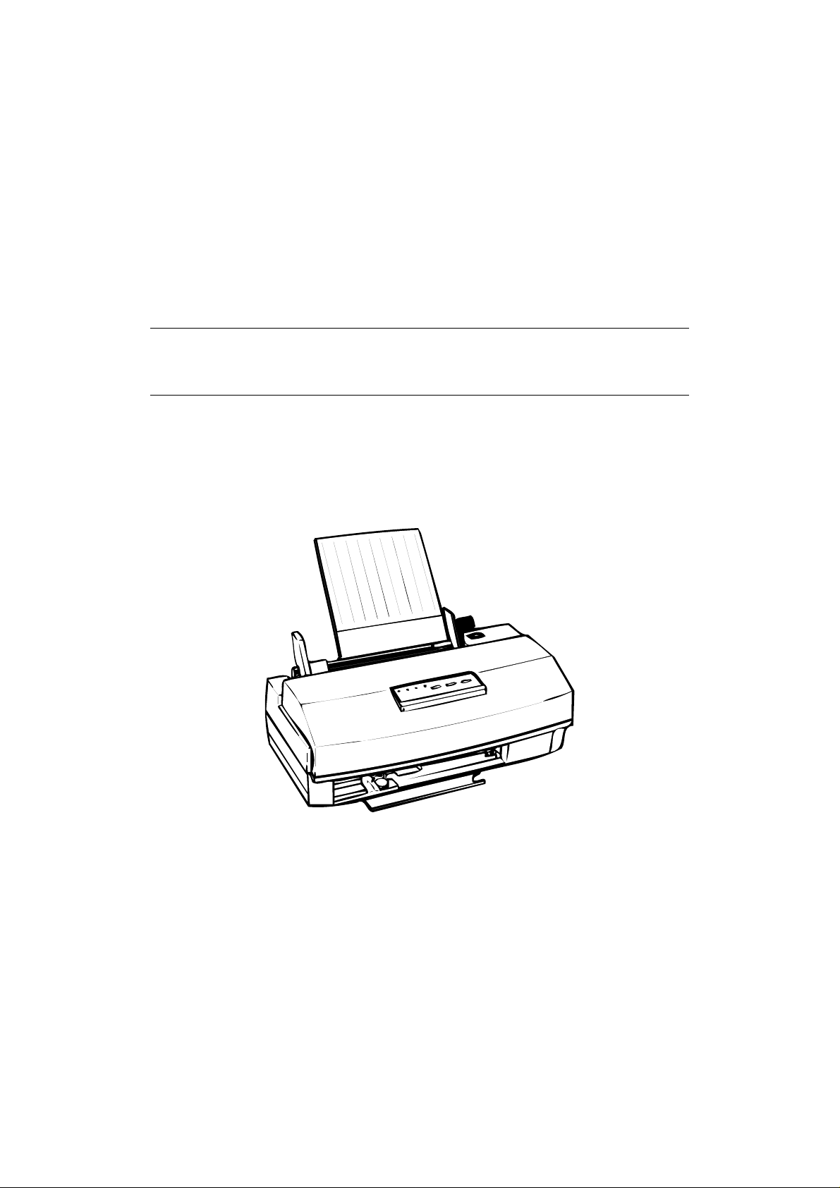
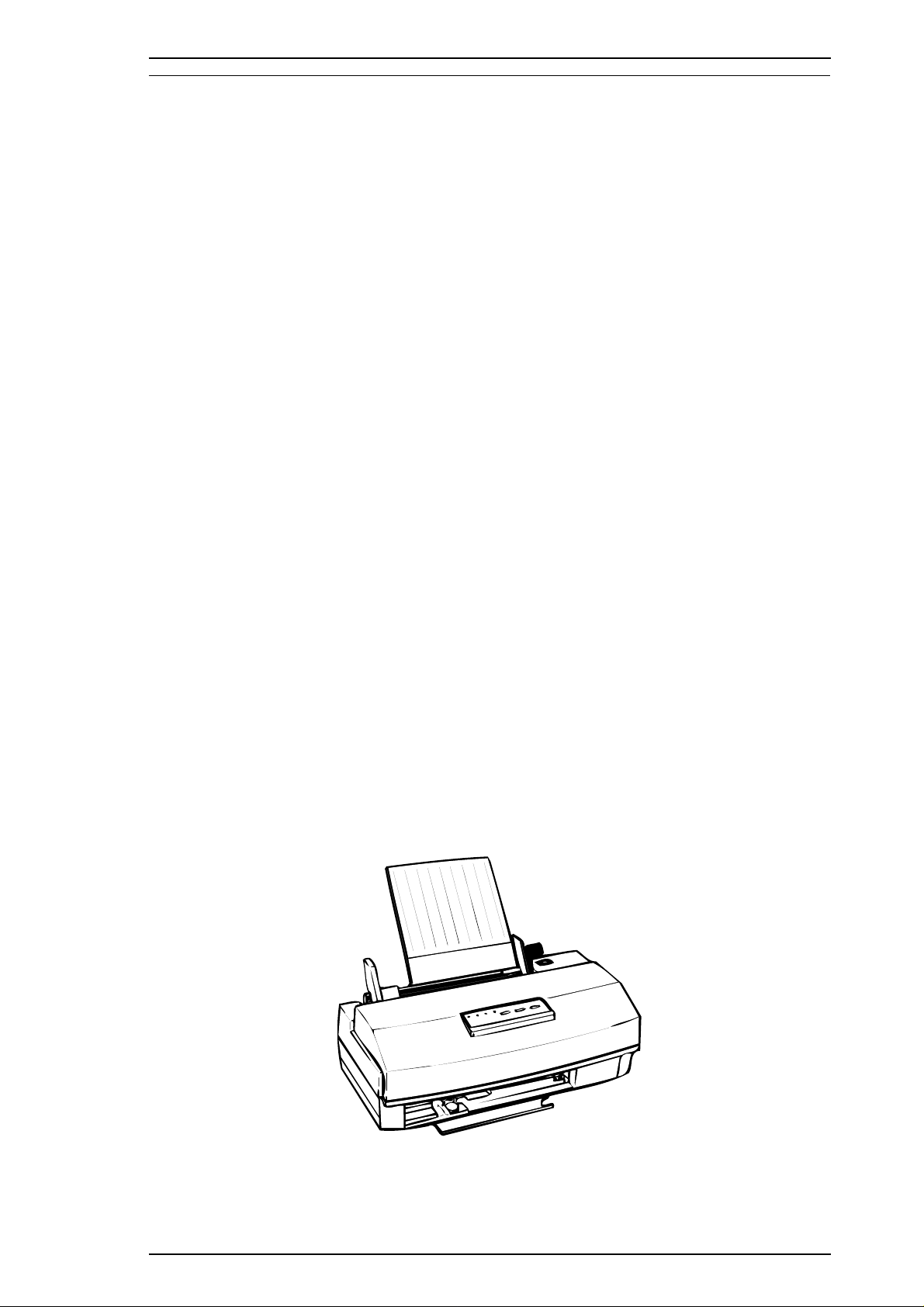
The figure below shows the Stylus Color IIs.
Figure 1-1. Exterior Viewing of Stylus Color IIs(820)
Rev. A 1-1
Page 10
Product Description Stylus Color IIs / Stylus 820
1.2 SPECIFICATIONS
This section provides statistics and other detailed information for the printer.
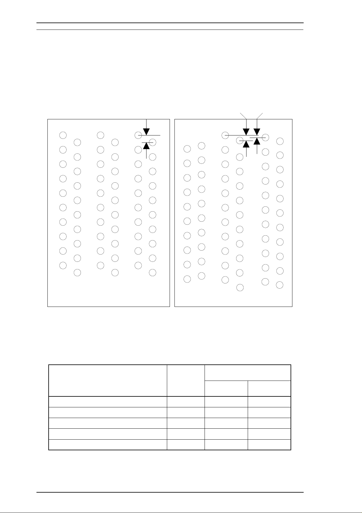
1.2.1 Printing Specifications
Print system: On-demand ink jet system
Nozzle configuration:
64 nozzles (10 × 2+11× 4 standard ): monochrome
60 nozzles (20 × 3 standard): color
120 dpi
120 dpi
360 dpi
#1
#19
#1 #1
#2 #2 #2
#19
#20
#19
#20 #20
(Row M) (Row C) (Row Y)
#1
#5
#6
#59
#60
(A) (B) (C) (D) (E) (F)
#4
#61
#64
#2
#62
#3
#63
Figure 1-2. Nozzle Configuration
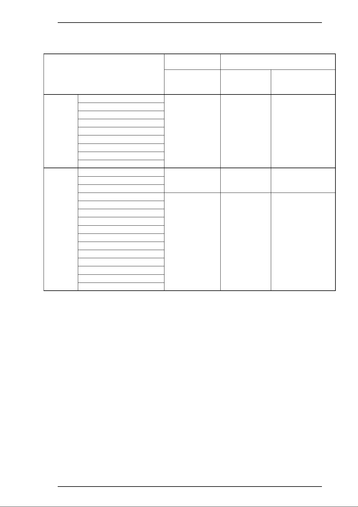
Printing direction: Bidirectional with logic-seeking
Table 1-1. Print Speed and Printable Columns
Character
Pitch
10 cpi (Pica) 80 125 170
12 cpi (Elite) 96 150 204
15 cpi 120 188 255
17 cpi (Pica condensed) 136 214 290
20 cpi (Elite condensed) 160 250 340
Printable
Columns
Printing Speed (cps)
Monochrome CMY
1-2 Rev. A
Page 11
Stylus Color IIs / Stylus 820 Product Description
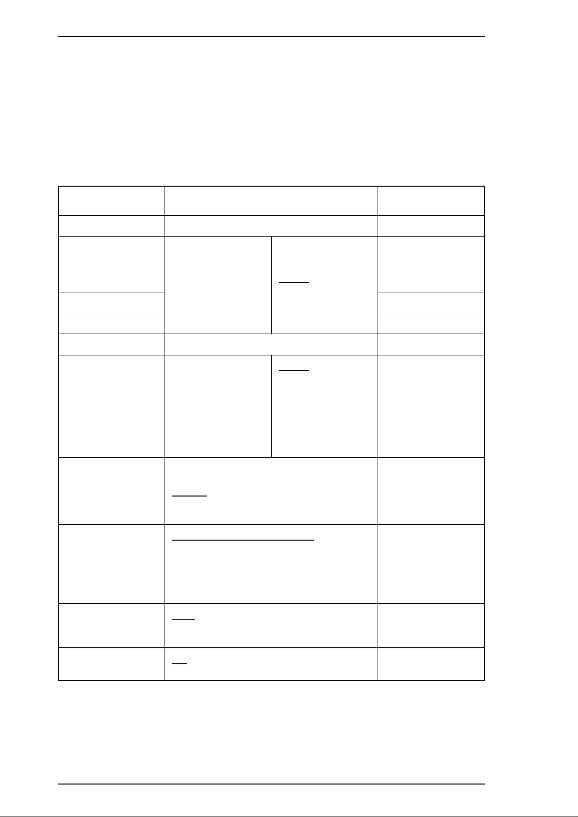
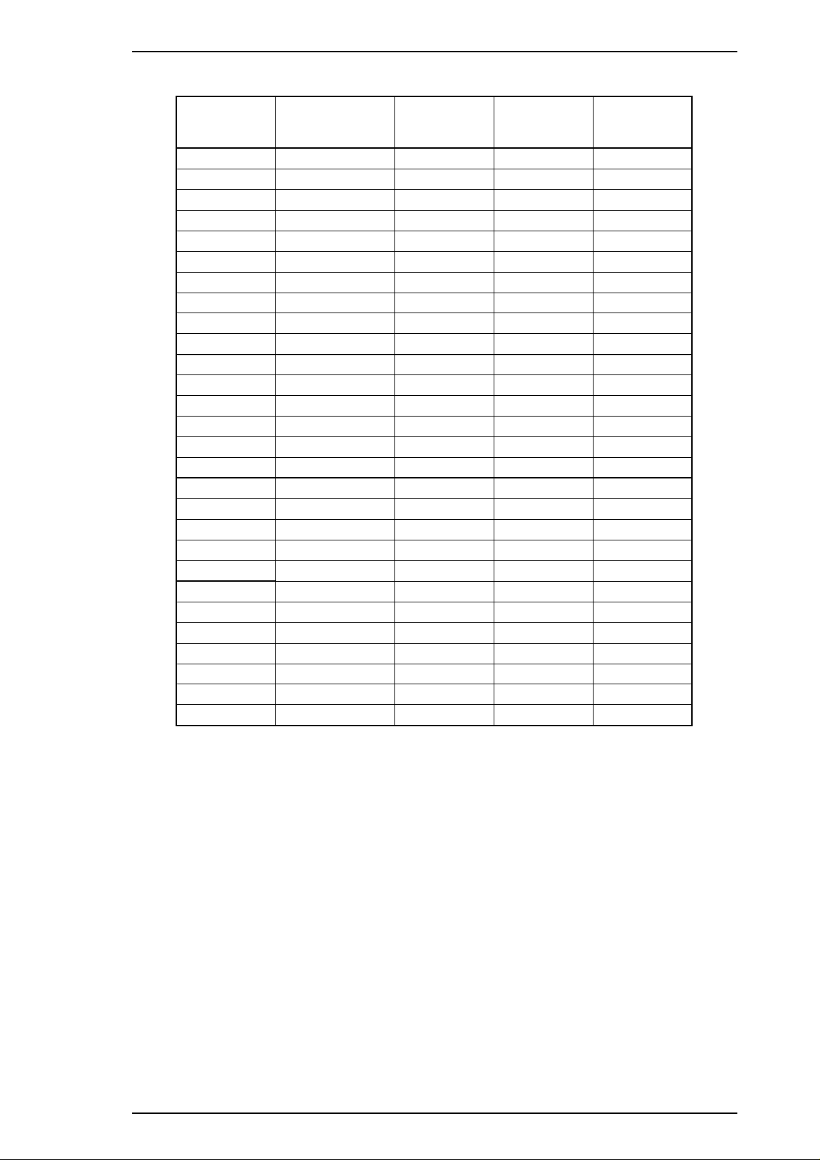
Character tables: Legal and 14 international sets
Table 1-2. Character Tables
Bitmap Fonts Scalable Fonts
Character Tables
Italic
PC437 (U.S./Standard Europe)
PC850 (Multilingual)
PC860 (Portuguese)
Standard
NLSP
Fonts: Bitmap LQ fonts
PC861 (Icelandic)
PC863 (Canadian-French)
PC865 (Nordic)
Abicomp
BRASCII
Italic
PC437 (U.S./Standard Europe)
PC850 (Multilingual)
PC437 (Greek)
PC852 (East Europe)
PC853 (Turkish)
PC855 (Cyrillic)
PC857 (Turkish)
PC866 (Russian)
PC869 (Greek)
MAZOWIA (Poland)
Code MJK (Czecho/Slovakia)
ISO 8859-7 (Latin/Greek)
ISO Latin 1T (Turkish)
Bulgaria (Bulgaria)
- EPSON Roman (10 cpi/12 cpi/15 cpi/Proportional)
- EPSON Sans Serif (10/12/15/Proportional)
- EPSON Courier (10/12/15)
EPSON Roman
EPSON Sans Serif
EPSON Courier
Supported Supported Supported
Supported Supported Supported
Supported Supported Not supported
EPSON Roman
EPSON Sans
Serif
EPSON Roman T
EPSON Sans Serif H
Scalable fonts
- EPSON Roman 10.5 points, 8 ∼ 32 points (in units of 2 points)
- EPSON Sans Serif 10.5 points, 8 ∼ 32 points (in units of 2 points)
- EPSON Roman T 10.5 points, 8 ∼ 32 points (in units of 2 points)
- EPSON Sans Serif H 10.5 points, 8 ∼ 32 points (in units of 2 points)
Control codes: ESC/P 2 and expanded raster graphics codes
Input data buffer: 0.5KB or 64KB
Rev. A 1-3
Page 12
LM
PW
RM
PL
BM
TM
Product Description Stylus Color IIs / Stylus 820
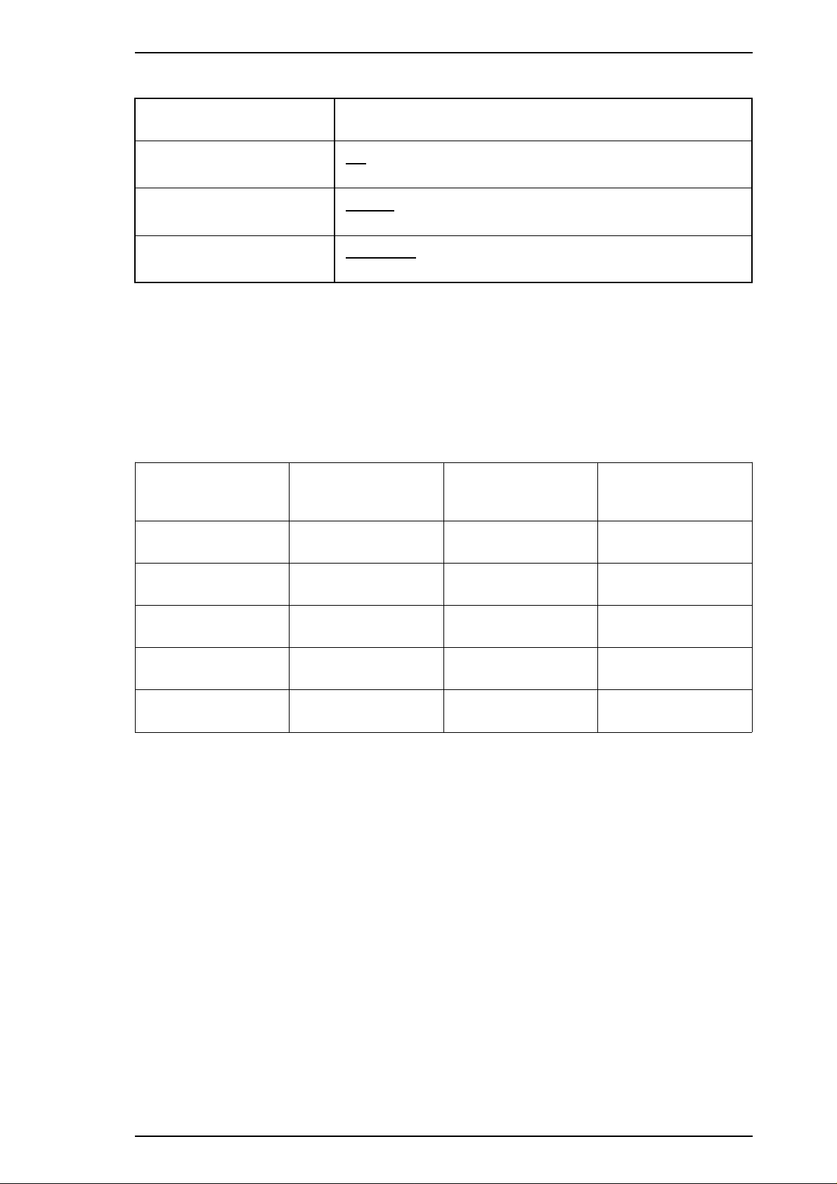
1.2.2 Paper Handling Specifications
Feeding method: Friction feed paper is fed from the built-in auto sheet feeder (ASF).
Line spacing: 1/6 inch feed or programmable in 1/360 inch minimum increments.
Paper path: Cut sheets are fed from the built-in auto sheet feeder (ASF).
Top in and front out.
Feeding speed: 102 msec. (at 1/6-inch feed pitch).
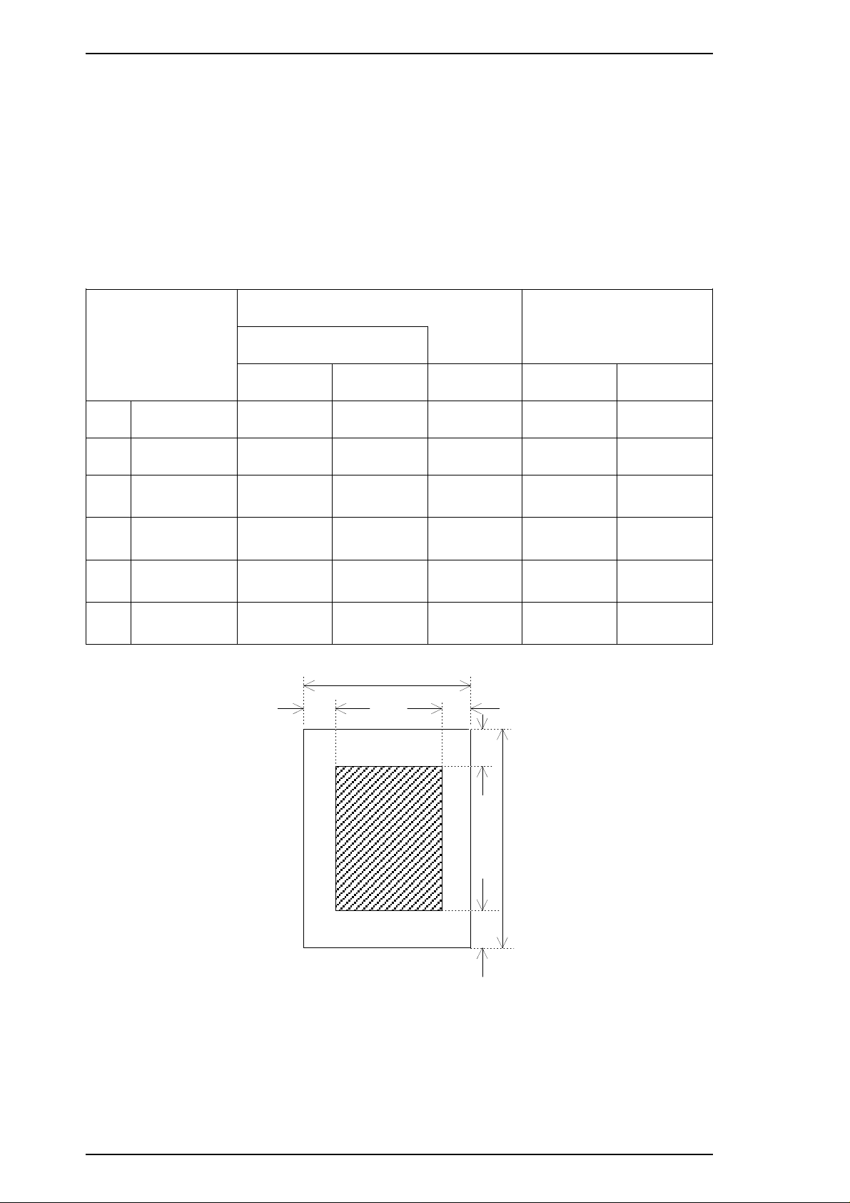
1.2.3 Paper Specifications
Table 1-3. Paper Specifications
Cut Sheets
Envelopes
Transparencies
A4 Letter Legal No. 10 DL
Width 210 mm 216 mm 216 mm 240 mm 220 mm
PW
Length 297 mm 279 mm 358 mm 104 mm 110 mm
PL
LM Left margin
RM Right margin
TM Top margin
BM Bottom margin
3 mm or
more
3 mm or
more
3 mm or
more
14 mm or
more
3 mm or
more
3 mm or
more
3 mm or
more
14 mm or
more
3 mm or
more
3 mm or
more
3 mm or
more
14 mm or
more
3 mm or
more
3 mm or
more
3 mm or
more
14 mm or
more
3 mm or
more
3 mm or
more
3 mm or
more
14 mm or
more
Figure 1-3. Printable Area
1-4 Rev. A
Page 13
Paper In
Paper Out
Manual Feed
Auto Feed
Hopper
Paper Select Lever
Thicker Paper
Thinner Paper
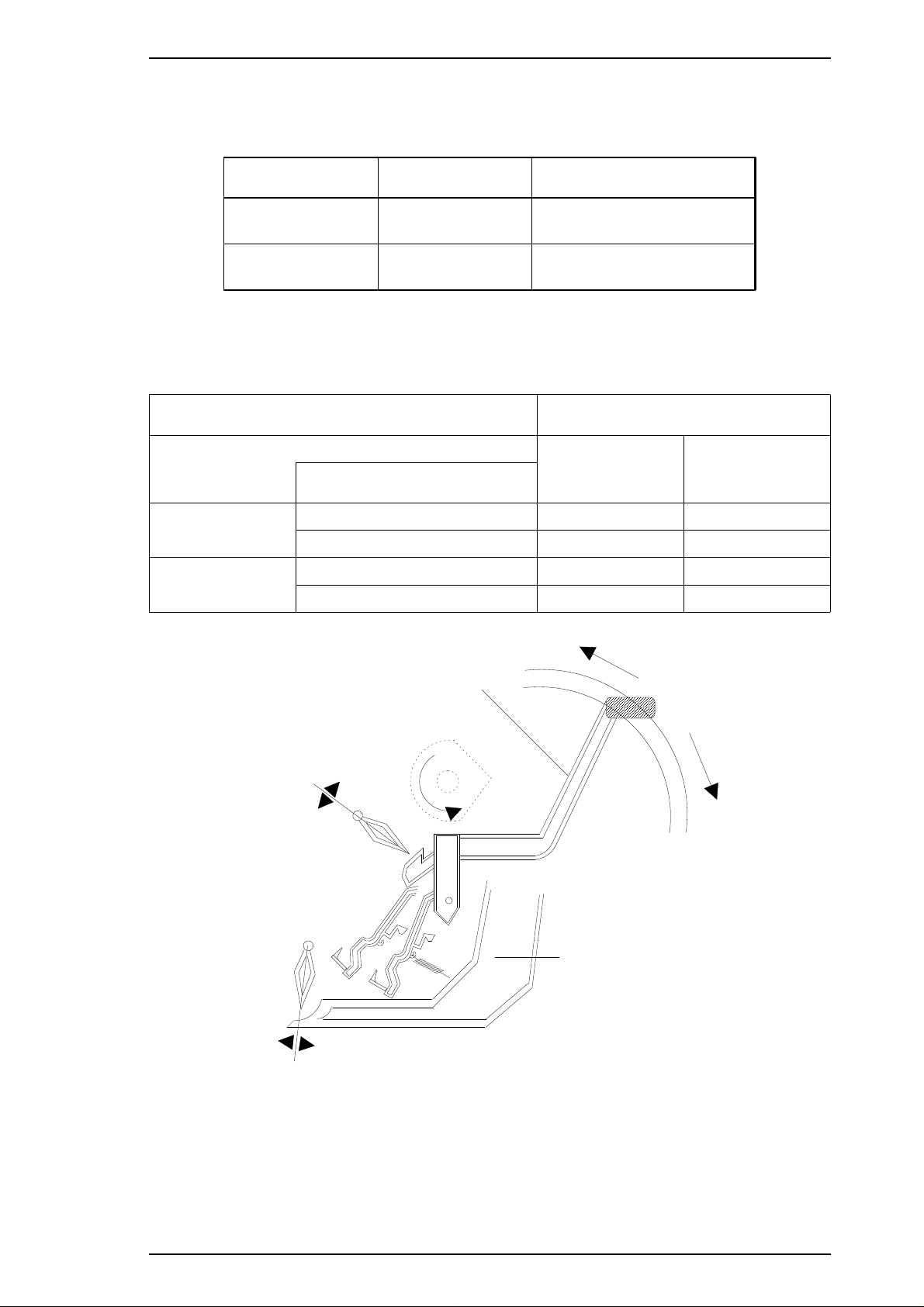
Stylus Color IIs / Stylus 820 Product Description
The adjust lever on the upper case must be set to the proper position for the paper
thickness, as shown in Table 1-4.
Table 1-4. Adjust Lever Settings
Lever Position Paper Paper Thickness
Front
(0 position)
Rear
(+ position)
Also the paper select lever on the upper case must be set to the proper position for
the paper varieties shown in Table 1-5.
Normal position 0 mm
Table 1-5. Paper Select Lever Settings
Specifications for the Medium
PF Mode Cut Sheets
Thick paper (Rear) NO OK
ASF Feed
Thinner paper (Front) OK NO
Thick paper (Rear) OK OK
Manual Feed
Thinner paper (Front) NO NO
Lever Position
0.62 mm
Envelopes
Postcards
Figure 1-4. Paper Select Lever
Note:
Rev. A 1-5
“OK” means paper can be used and “NO” means paper cannot.
Page 14
Product Description Stylus Color IIs / Stylus 820
1.2.4 Ink Cartridge Specifications
Table 1-6. Black I/C Specifications
Item Specifications
Type Exclusive cartridge
Color and Weight
Ink Life High-quality ink produces 800 thousand characters
Validity 2 years (sealed in package) / 6 months (out of package)
Storage
Temperature
Dimensions
Approximately 54 g (internal ink weight is 36 g ± 0.5 g)
❏ –30 to 40° C(−22 ∼ 104° F) (Storage: a month or less at 40° C (104° F))
❏ –20 to 40° C(−15 ∼ 104° F) (Transit: a month or less at 40° C (104° F))
❏ –30 to 60° C(−22 ∼ 140° F) (Transit: 120 hours or less at 60° C (140° F))
30.0 (W) × 58.0 (D) × 38.5 ± 0.3 (H) mm
Table 1-7. Color I/C Specifications
Item Specifications
Type Exclusive cartridge
Color and Weight
Ink Life 100% solid pattern: A4 — 16 sheets / each color
Validity 2 years (sealed in package) / 6 months (out of package)
Storage
Temperature
Approximately 70 g (internal ink weight is 12.8 g ± 0.5 g)
❏ –30 to 40° C(−22 ∼ 104° F) (Storage: a month or less at 40° C (104° F))
❏ –20 to 40° C(−15 ∼ 104° F) (Transit: a month or less at 40° C (104° F))
❏ –30 to 60° C(−22 ∼ 140° F) (Transit: 120 hours or less at 60° C (140° F))
Dimensions
42.9 (W) × 56.5 (D) × 38.5 ± 0.3 (H) mm
1-6 Rev. A
Page 15

80%
55%
20%
Humidity
(% RH)
Guaranteed Range
(Degrees)
10 27 35
Stylus Color IIs / Stylus 820 Product Description
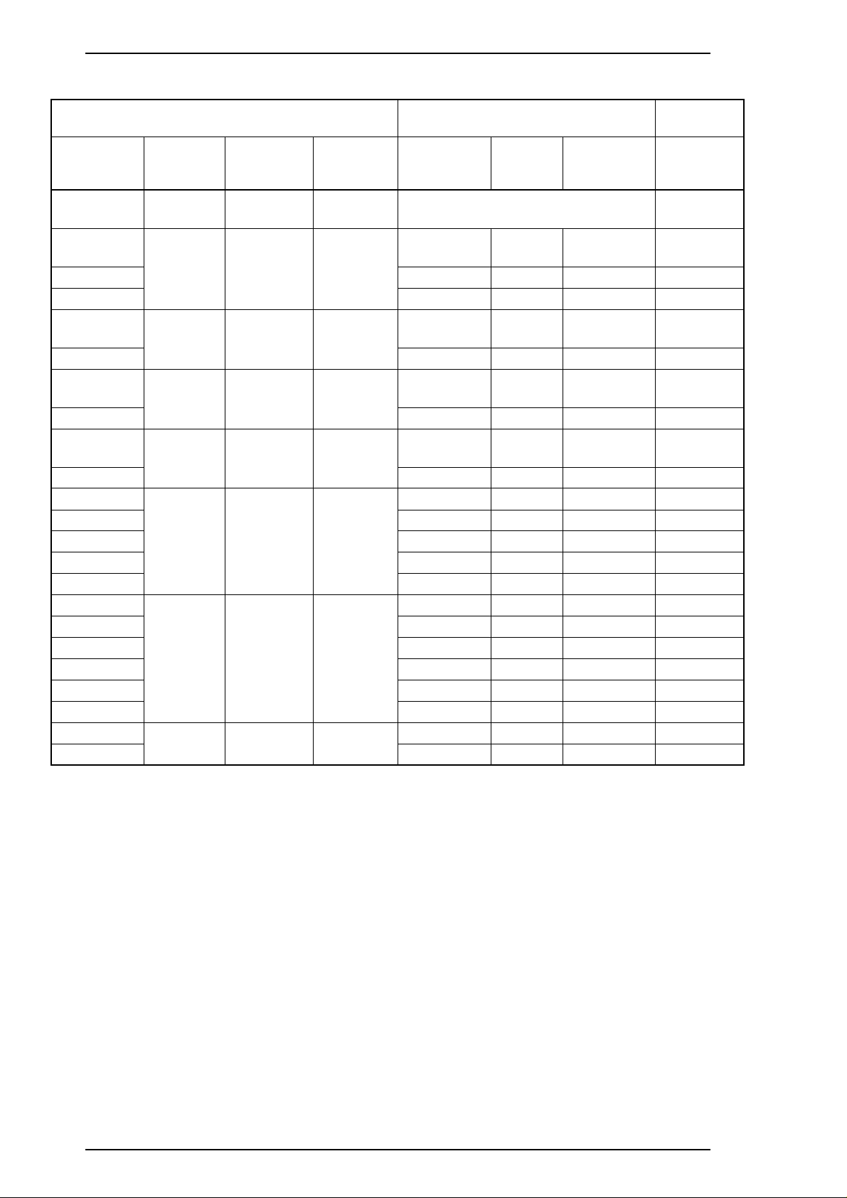
1.2.5 Electrical Specifications
Table 1-8. Rated Electrical Ranges
Specification 120 V Version 220 - 240 V Version
Rated voltage 120 VAC 220 - 240 VAC
Input voltage range
Rated frequency range
Input frequency range
103.5 ∼ 132 V 198 ∼ 264 V
50 ∼ 60 Hz 50 ∼ 60 Hz
49.5 ∼ 60.5 Hz 49.5 ∼ 60.5 Hz
Rated current 0.5 A 0.3 A
Power consumption
Insulation resistance
Dielectric strength
Approx. 13 W
(self-test with 10-cpi LQ characters)
10 MΩ, minimum
(applying 500 VDC between AC line
and chassis)
1000 VAC rms for 1 minute or
1200 VAC rms for 1 second
(between AC line and chassis)
(self-test with 10-cpi LQ characters)
(applying 500 VDC between AC line
(between AC line and chassis)
Approx. 13 W
10 MΩ, minimum
and chassis)
1500 VAC rms for 1 minute
1.2.6 Environmental Conditions
Table 1-9. Acceptable Environmental Conditions
Condition Operating Non Operating
*1, 3
*1
−20 ∼ 60° C (−4 ∼ 122° F)
5 ∼ 85% RH
Temperature
Humidity
10 ∼ 35° C (50 ∼ 95° F)
20 ∼ 80% RH
Shock resistance 1G (within 1 msec.) 2G (within 2 msec.)
Vibration resistance 0.15 G 0.50 G
*1
: For printer operation, conditions must be in the range shown in the figure below.
*2
: These conditions are applicable when the printer is in its shipping container.
*3
: Without condensation.
*2
*2, 3
*2
*2
Figure 1-5. Temperature / Humidity Range
Rev. A 1-7
Page 16

Product Description Stylus Color IIs / Stylus 820
1.2.7 Reliability
Total print volume: 25,000 pages (A4, letter)
Printhead life: 500 million dots/nozzle (color and monochrome)
1.2.8 Safety Approvals
Safety standards: 120 V version: UL1950 with D3,
CSA C22.2 # 950 with D3
220-240 V version: EN 60950 (TÜV, SEMKO, DEMKO,
NEMKO, SETI)
Radio frequency interference (RFI): 120 V version: FCC Part 15 Subpart B Class B
220-240 V version: Vfg.243 (VDE0878 part 3, part 30)
EN55022 (CISPR PUB. 22) class B
CSA C108.8
1.2.9 Acoustic Noise
Level: Approximately 45 dB (A) (Per ISO 7779)
1.2.10 Physical Specifications
Dimensions (W × D × H): 396.7 mm (W) × 205.6 mm (D) × 144.0 mm (H)
Weight: About 3.9 kg (8.6 lb.), excluding head and ink cartridge
1-8 Rev. A
Page 17
Stylus Color IIs / Stylus 820 Product Description
1.3 INTERFACE SPECIFICATIONS
The Stylus Color IIs is standard-equipped with an 8-bit parallel and serial interface.
1.3.1 Parallel Interface Specifications
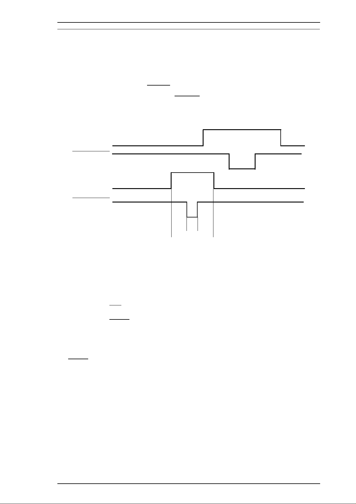
Data format: 8-bit parallel
Synchronization: By
Handshaking: By BUSY and
Signal level: TTL compatible level
Adaptable connector: 36-pin 57-30360 (Amphenol) or equivalent
STROBE pulse synchronization
ACKNLG signals
BUSY
ACKNLG
5 µsec (min.)
DATA
STROBE
0.5 µsec (min.)
0.5 µsec (min.)
0.5 µsec (min.)
Figure 1-6. Data Transmission Timing
Data transmission timing: See Figure 1-6.
0 µsec(min.)
Note:
The Busy signal is active (HIGH) under the following conditions:
The
The PE signal is active (HIGH) under the following conditions:
Transition time (rise time and fall time) of every input signal must be less than 0.2 µs.
❏ During data reception (See Figure 1-6.)
❏ When the input buffer is full
❏ When the
❏ During initialization
❏ When the
❏ During the self-test mode
❏ During the demonstration mode
❏ During the default setting mode
❏ When a fatal error occurs
ERROR signal is active (LOW) under the following conditions:
❏ When a paper-out error occurs
❏ When a no ink cartridge error occurs
❏ When a fatal error occurs
❏ When a paper-out error occurs
❏ When a fatal error occurs
INIT input signal is active
ERROR or PE signal is active
Rev. A 1-9
Page 18
Product Description Stylus Color IIs / Stylus 820
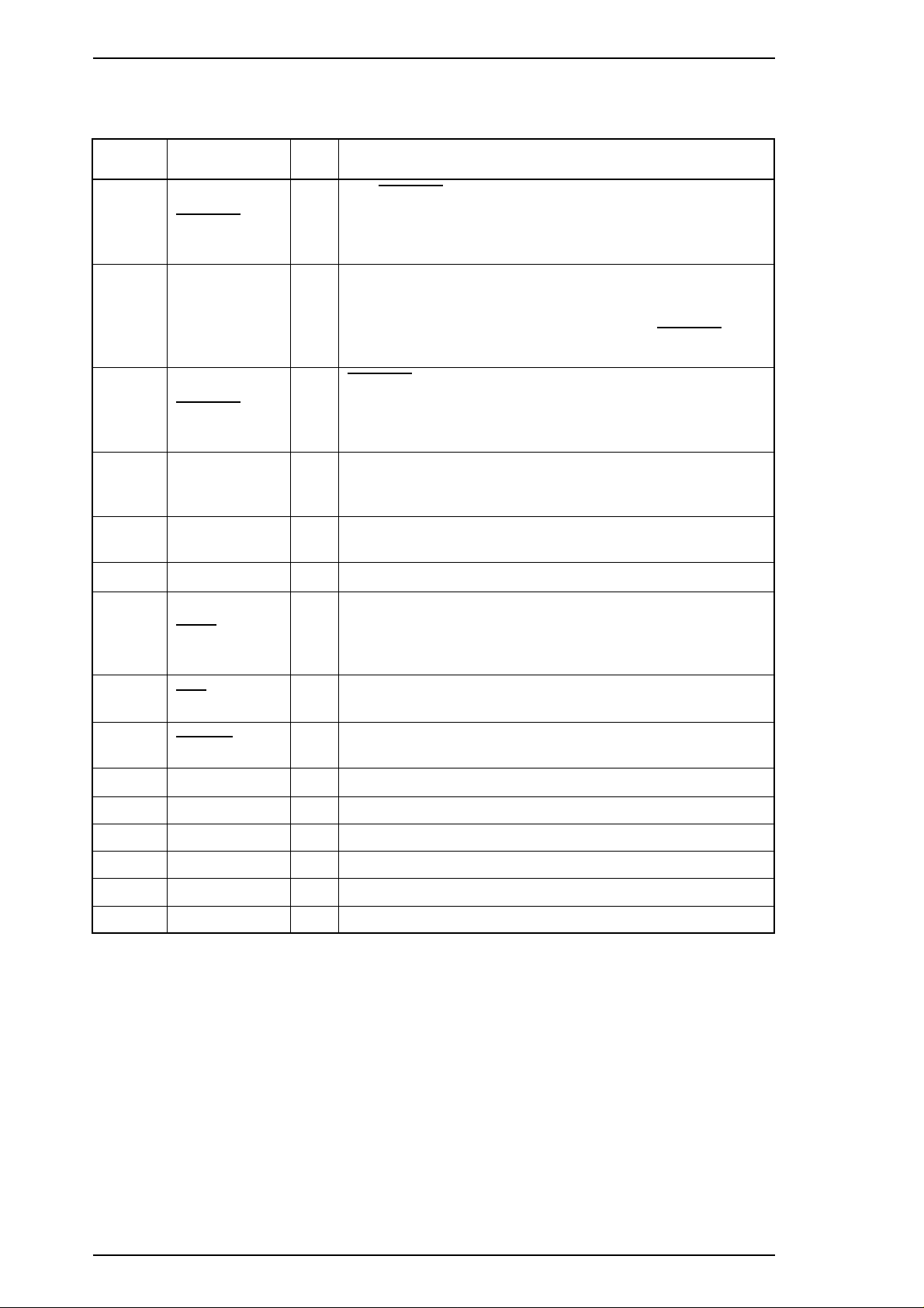
Table 1-10 shows the connector pin assignments and signal functions of the 8-bit parallel interface.
Table 1-10. Signal and Connector Pin Assignments for Parallel Interface
Pin No. Signal Name I/O* Description
STROBE pulse is used to read data from the host
The
1
2-9 DATA 1-8 I
10
11 BUSY O
STROBE I
ACKNLG O
computer. The pulse width must be 0.5 µs or more. Normally,
it is HIGH, and data is latched with the rising edge of this
signal.
DATA 1-8 are parallel data bits. When one of these signals is
HIGH, the data bit is 1; when LOW, the data bit is 0. The
most significant bit (MSB) is DATA 8. The signal state must
be maintained for 0.5 µs on either side of the
signal’s active edge.
ACKNLG is an acknowledge pulse with a width of
approximately 10 µs. This signal goes LOW upon the
completion of data reception to indicate that the printer is
ready to receive further data.
The BUSY signal informs the host computer of the printer’s
status. When this signal is HIGH, the printer cannot accept
any more data.
STROBE
12 PE O
13 SLCT O
14
31
32
35 +5 V —
17 CHASSIS — Chassis ground.
16 GND — Signal ground.
19-30 — — —
33,36 — — Not used.
15,18,34 — — —
AFXT I
INIT I
ERROR O
This signal indicates whether paper is available in the printer
or not. A HIGH level indicates no paper.
Pulled up to +5 V through a 1.0 KΩ resistor in the printer.
If this signal is set to LOW, the printer automatically performs
one line feed upon receipt of a CR (carriage return) code. The
status of this signal is checked only at power on and
initialization.
If this signal goes LOW, the printer is initialized. The pulse
width of this signal must be 50 µs or more.
This signal goes LOW if the printer has a fatal error or runs
out of paper.
Pulled up to +5 V through 1.0 KΩ resistor in the printer.
* The I/O column indicates the direction of the signal as viewed from the printer.
1-10 Rev. A
Page 19
Stylus Color IIs / Stylus 820 Product Description
1.4 OPERATIONS
This section describes the basic operations of the printer.
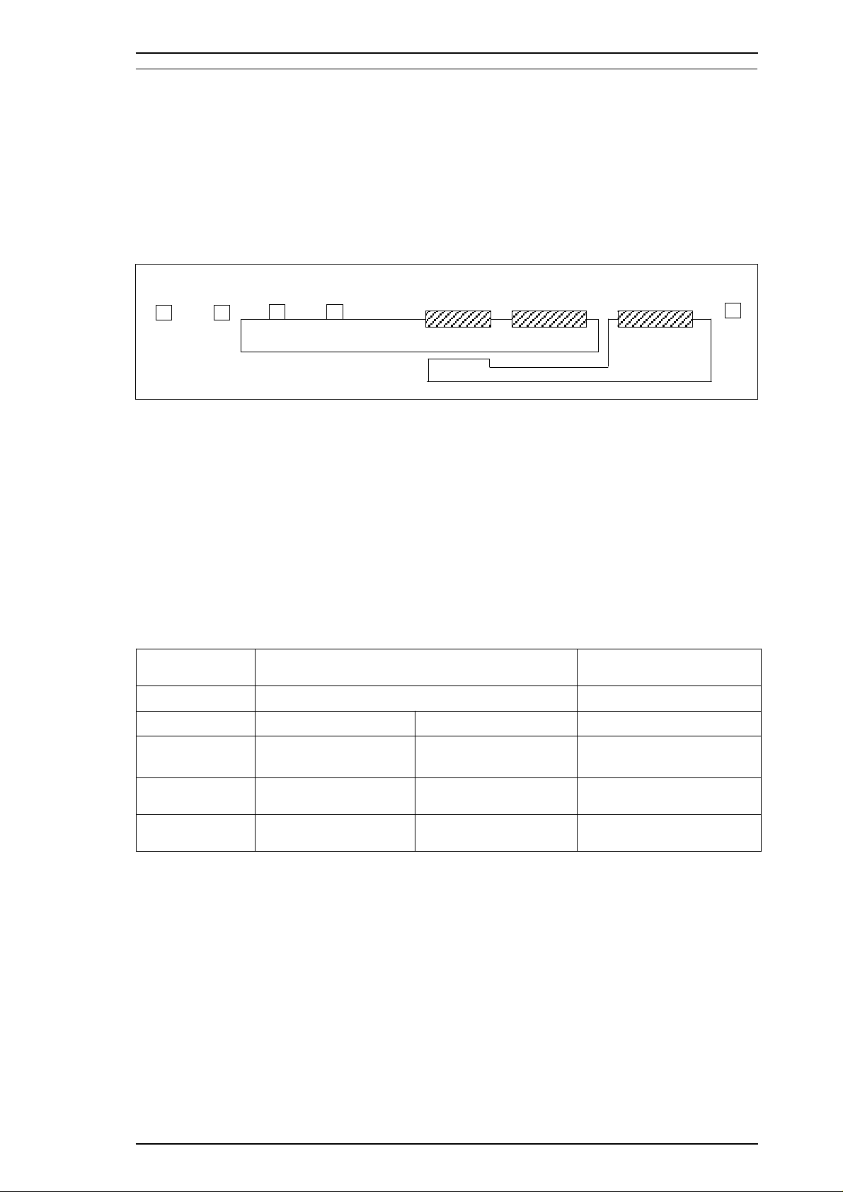
1.4.1 Control Panel
The control panel for this printer has 3 non-lock-type push buttons, and 5 LED indicators for easy operation
of the various printer functions.
Power
Error
Condensed
Economy
Alt
Load / Eject
Figure 1-7. Control Panel Appearance
1.4.2 Panel Operation and Built-in Function
You can activate the following modes by doing the procedure in table 1-11 and 1-12.
Table 1-11. Panel Operation
Button
^
^
Operations
Single Button Operations Combined with Alt Button
Pressed and released Held down 3 seconds Pressed and released
+
Pause
Cleaning
Alt
Load/Eject
Pause
Rev. A 1-11
No function
Load/Eject
Pause
I/C or head unit
replacement
No function Economy/Condensed
Reset Cleaning
———
Page 20
Product Description Stylus Color IIs / Stylus 820
Table 1-12. Built-in Functions on the Panel
Button
Alt
Load/Eject
Pause
Alt + Load/Eject
Load/Eject + Pause
Pause + Alt
Pause + Load/Eject + Pause
Other combinations
Table 1-13. Button Operations in Default Setting Mode
Button
Alt
Pause
Function
Demonstration printing
Self-test
Default setting mode (with printing)
Non-smear printing
Data dump mode (Hex mode)
Default setting mode (without printing)
Reset to the default settings
Not available
Function
Move to the next item or menu
Set item
1-12 Rev. A
Page 21
Stylus Color IIs / Stylus 820 Product Description
Indicators
Power
Error
Condensed
Economy
Pause
LED combinations See Table 1-14.
On when printer is on. Blinks during power on and off.
On when printer encounters an error, such as ink end, paper out, paper
jam, etc.
On when printer is in the condensed mode (50% or 80%).
On when printer is in the economy mode.
On when printer is paused.
Table 1-14. Error Indications
Printer Status
^
Pause
Economy
Condensed
Panel reset accepted
Ink low (printable)
Ink out (unprintable)
Power
On
On
On
On
On Blinks
On
Indicators +
Error Condensed Economy Pause
———On
— — On —
On On — —
Blinks On On On
(rapidly)
On — — On
———
Paper out
Paper jam
Head, I/C replacement
Head, I/C not installed
(in replacement mode)
Head, I/C not installed
Carriage control error
Maintenance request
On
On
On
On
On
On
On
Off — — On
Off — Blink On
Blinks — — Blinks
Blinks — — Blinks
Blinks Off Off Blinks
Blinks Blinks Off Blinks
Blinks Blinks Blinks Blinks
Rev. A 1-13
Page 22
Product Description Stylus Color IIs / Stylus 820
1.4.3 Default Settings
The printer can save some printer setting parameters that define its functions at initialization. You can
change these parameters using the printer’s default setting mode.
1.4.3.1 Default Setting Items
You can use default setting mode to change settings listed in the table below. Activate default-setting mode
by holding down the
turning on the printer.
Pause
or the
Pause
and
Alt
buttons (for default setting mode without printing) while
Table 1-15. Default Setting Items
Item
Character Tables
^
^
^
^
^
Typestyles
Selections
Standard Version +
Italic USA
Italic France
Italic Germany
Italic UK
Italic Denmark
Italic Sweden
NLSP Version +
Italic USA
Italic France
Italic Germany
Italic UK
Italic Denmark
Italic Sweden
Italic Italy
Italic Spain
Roman
Sans Serif
Italic Italy
Italic Spain
PC437
PC850
PC860
PC863
PC437
PC850
PC853
PC857
PC437 Greek
PC855
PC866
PC852
Courier
Roman T (PS)
Sans Serif H (PS)
+
PC865
PC861
BRASCII
Abicomp
^
^
PC869
ISO 8859-7
ISO Latin 1T
MAZOWIA
Code MJK
Bulgaria
+
10 CPI (10 CPI, Condensed off)
12 CPI (12 CPI, Condensed off)
Character Pitches
15 CPI (15 CPI, Condensed off)
17.1 CPI (10 CPI, Condensed on)
+
20 CP I(12 CPI, Condensed on)
Proportional (PS, Condensed off)
Auto
Print Direction
Bidirectional
+
Uni-directional
Network I/F Mode
1-14 Rev. A
Off (Usual environment)
On (Network environment)
+
Page 23
Stylus Color IIs / Stylus 820 Product Description
Table 1-15. Default Setting Items (Continued)
Item
Auto line feed
Loading position
Thick paper
Note:
The underlined value is the factory setting.
Off
On
8.5 mm
3 mm
Envelopes
Index card (portrait)
Contents
1.4.3.2 Changing the Default Settings
To change the printer’s default settings:
1.
Hold down the
firmware version and describes how to select the language used to print messages. You can select a
language by pressing the
Pause
button and turn on the printer. The printer outputs a sheet that shows the
Alt
button, and set it by pressing the
Pause
button. (See Table 1-16.)
Table 1-16. Language Selection
Error
LED
Condensed
LED
Economy
LED
English
Francias
Deutsch
Italiano
Español
2.
Press the
prints a table showing how to change printer settings.
3.
Press the
by the
to the next setting, and the three font LEDs change according to the selection.
4. After you set all values, turn the printer off to save the new settings.
Pause
Alt
Error,Condensed
button. The printer prints the current settings using the selected language. It also
button to advance through the setting menus. The current printer settings are indicated
, and
On Off Off
Off On Off
On On Off
Off Off On
On Off On
Economy
LEDs. Each time you press the
Pause
button, you advance
Rev. A 1-15
Page 24
Product Description Stylus Color IIs / Stylus 820
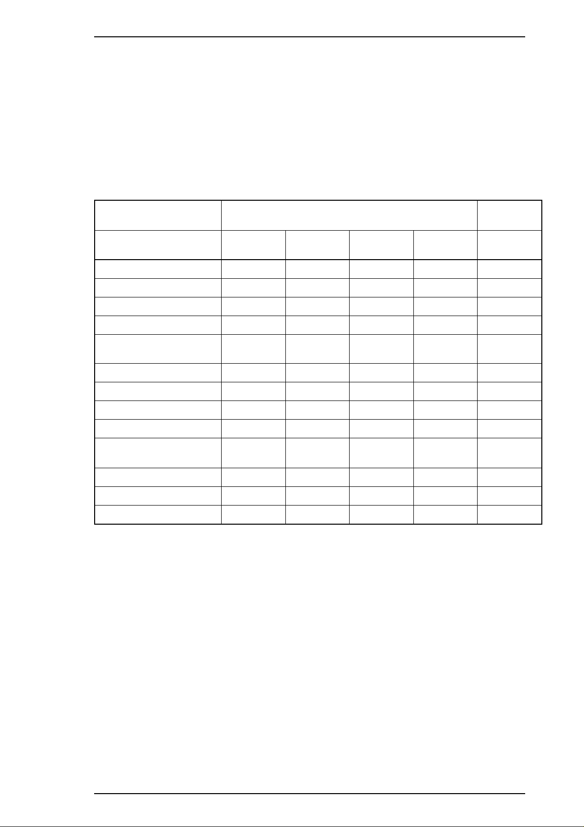
Table 1-17. Feature Selections
Menu
Feature/
Menu
Character
Table
Print
Direction
^
^
Network
I/F Mode
^
Auto Line
Feed
^
Loading
Position
^
Font
^
^
^
^
Pitch
^
^
^
^
^
Thick Paper
^
Setting Value
Error
LED
On Off Off See Table 1-18. +
Off On Off
On On Off
Off Off On
On Off On
Off On On
On On On
Off Off Off
Condensed
LED
Economy
LED
Setting
Auto Blinks Off Off
Bi-D Blinks On Off
Uni-D Blinks Off On
Off Blinks Off Off
On Blinks On Off
Off Blinks Off Off
On Blinks On Off
3 mm Blinks Off Off
8.5 mm Blinks On Off
Roman Blinks Off Off
Sans serif Blinks On Off
Courier Blinks Off On
Roman T Blinks On On
Sans serif H Off Blinks Off
10 CPI Blinks Off Off
12 CPI Blinks On Off
15 CPI Blinks Off On
17.1 CPI Blinks On On
20 CPI Off Blinks Off
Proportional On Blinks Off
Envelopes Blinks Off Off
Index cards Blinks On Off
Error
LED
Condensed
LED
Economy
+
LED
1-16 Rev. A
Page 25
Stylus Color IIs / Stylus 820 Product Description
Table 1-18. Character Table Selection
Version
Common
^
^
^
^
^
^
^
^
^
Standard
^
^
^
^
^
NLSP
^
^
^
^
^
^
^
^
^
^
^
Settings
Italic U.S.A. Blinks Off Off
Italic France Blinks On Off
Italic Germany Blinks Off On
Italic U.K. Blinks On On
Italic Denmark 1 Off Blinks Off
Italic Sweden On Blinks Off
Italic Italy Off Blinks On
Italic Spain 1 On Blinks On
PC437 Off Off Blinks
PC850 On Off Blinks
PC860 Off On Blinks
PC863 On On Blinks
PC865 Blinks Blinks Off
PC861 Blinks Blinks On
BRASCII Off Blinks Blinks
Abicomp On Blinks Blinks
PC437 Greek Blinks Blinks Off
PC853 Off On Blinks
PC855 Blinks Blinks Off
PC852 On Blinks Blinks
PC857 On On Blinks
PC866 Off Blinks Blinks
PC869 Blinks Off Blinks
MAZOWIA Off On On
Code MJK On On On
ISO 8859-7 Blinks On Blinks
ISO Latin 1T Blinks Blinks Blinks
Bulgaria Off Off Off
Error LED
Condensed
LED
Economy
LED
Rev. A 1-17
Page 26

Product Description Stylus Color IIs / Stylus 820
1.4.4 Error Conditions
The printer can detect various errors and indicate them with LEDs. Refer to Table 1-14.
1.4.5 Printer Initialization
There are three initialization methods: hardware initialization, software initialization, and panel
initialization.
1.4.5.1 Hardware Initialization
Hardware initialization is performed by:
- Turning on the printer.
- Sending the parallel interface the
(If the
INIT signal is active when the printer is turned on, hardware initialization is started when the INIT
signal becomes inactive.)
When hardware initialization is performed:
- The printer mechanism is initialized.
- Input data buffer is cleared.
- Downloaded character definitions are cleared.
- Print buffer is cleared.
- Default values are set.
INIT signal.
1.4.5.2 Software Initialization
Software initialization is performed upon receipt of the control code ESC @.
When software initialization is performed:
- The print buffer is cleared.
- Default values are set.
1.4.5.3 Panel Initialization
Panel initialization is performed by holding down the Alt button for 3 seconds.
When the panel initialization is performed:
- The input data buffer is cleared.
- The print buffer is cleared.
- Default values are set.
1-18 Rev. A
Page 27
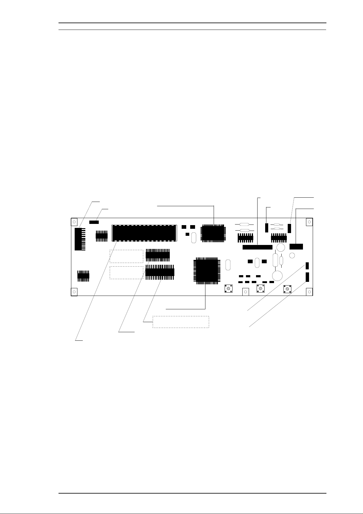
CN1
CN2
CN3
CN4
CN5
CN6
CN7
CN8
SW3 SW2 SW1
CPU M3772051 (IC2)
E05B08 (IC1)
4M or 8M Bit PROM (IC3)
1M Bit PSRAM (IC4)
8M Bit CG-ROM (IC5)
Stylus Color IIs / Stylus 820 Product Description
1.5 MAIN COMPONENTS
The main components of the Stylus Color IIs are:
❏ Printer mechanism (M-4C10)
❏ Main control board (C160 MAIN Board)
❏ Power supply unit (C160 PSB/PSE Board)
❏ Control panel board (C160 I/F Board)
❏ Housing
1.5.1 Main Control Board (C160 MAIN Board)
The main control board (C160 MAIN Board) consists of an M37720 16-bit CPU, E05B08 gate array, a
program ROM (4M), a PS-RAM (1M), a mask ROM (4M or 8M: If a 4M-bit program ROM is mounted on
the board, an 8M-bit CG-ROM is mounted in location IC5, and if an 8M-bit program ROM is mounted on
the board, there is no CG-ROM in location IC5.) and a 1K EEPROM. The reset IC (M51955 and PST 592)
is equipped with both a logic system and a power system.
Note:
During servicing, when you replace the program ROM, always install an 8M-bit program ROM
regardless of the components mounted on that particular board. When you do this, the
CG-ROM in location IC5 is ignored.
Rev. A 1-19
Figure 1-8. C160 Main Control Board Component Layout
Page 28
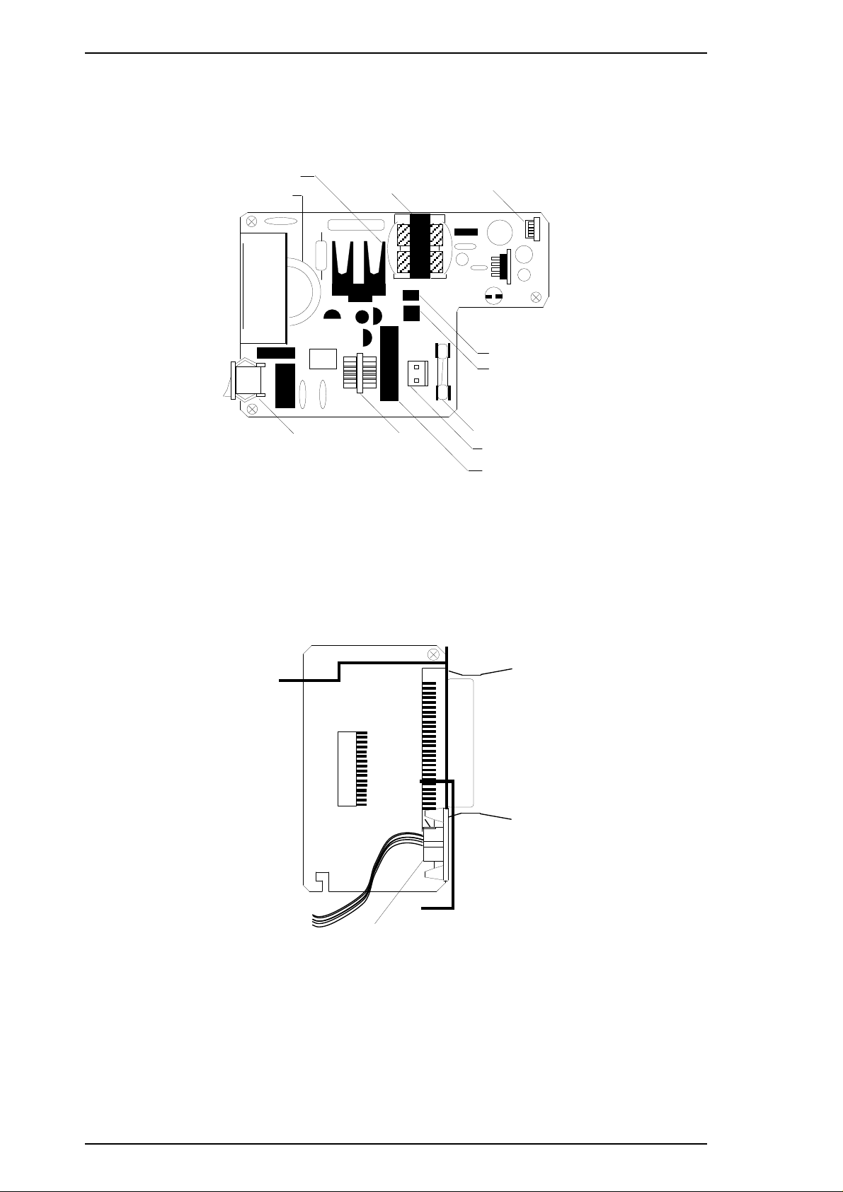
CN1
CN2
JAPAN version only (Serial I/F)
Product Description Stylus Color IIs / Stylus 820
1.5.2 Power Supply Board (C160 PSB/PSE Board)
The power supply board (C160 PSB/PSE Board) consists of an RCC switching regulator circuit. This
board does not have a power switch connected to the secondary circuit like the Stylus Color series. Thus, if
the printer is turned off, it cannot continue to operate in order to perform the head capping operation.
Q1 (FET)
C11
Power SW
Trans (T1)
Figure 1-9. C160 PSB/PSE Board Component Layout
1.5.3 Interface Board (C160 I/F Board)
Filter (L1)
CN2
Photo Coupler (PC1)
Photo Coupler (PC2)
Fuse (F1)
CN1
Choke Cil (C1)
There is an exclusive interface board to receive/transmit print data between the host computer and printer.
Figure 1-10. C160 I/F Board Component Layout
1-20 Rev. A
Page 29
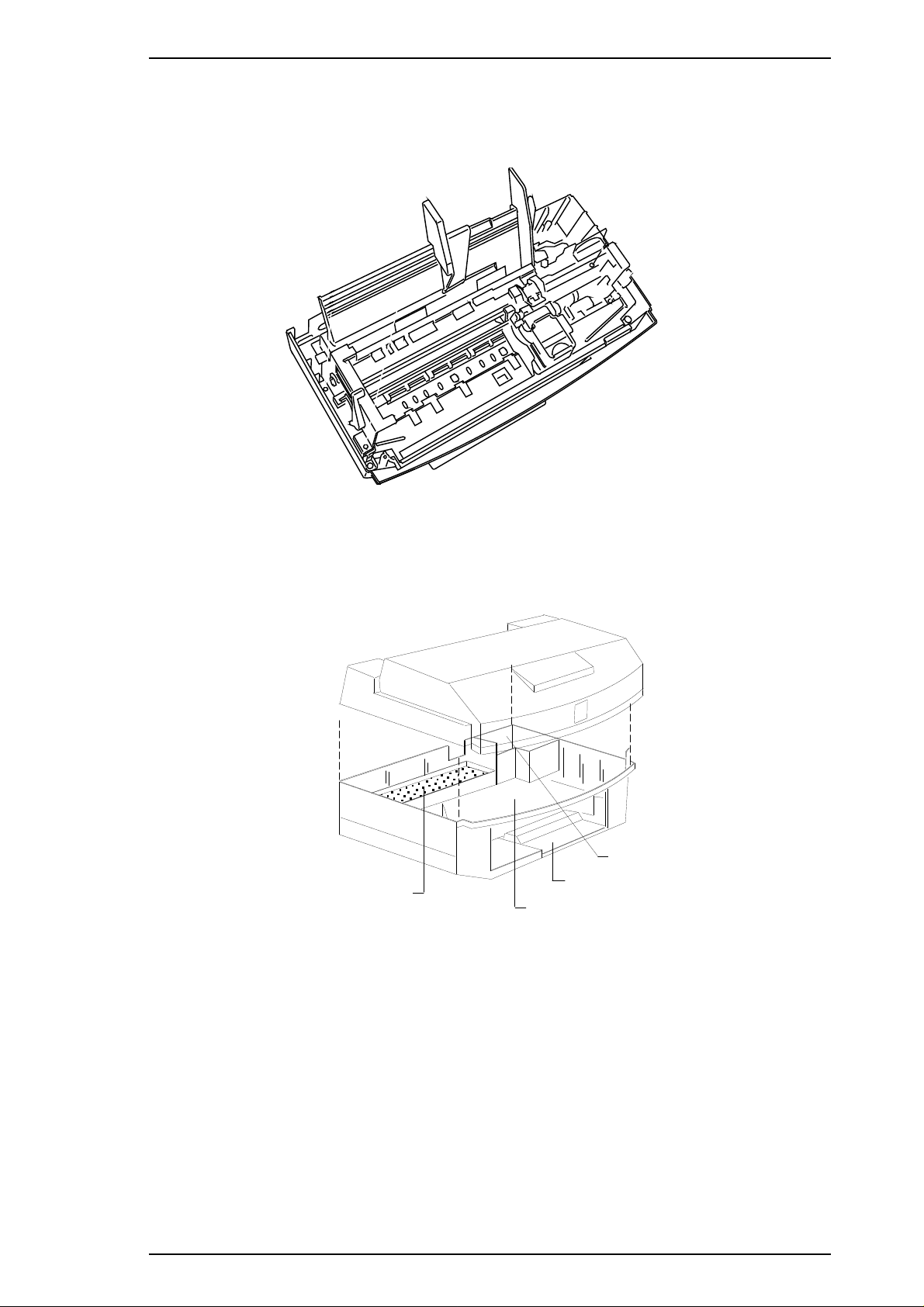
Upper Case
Eject Paper Stacker
M4C10 Mechanism Space
Waste Ink Drain Tank
Stylus Color IIs / Stylus 820 Product Description
1.5.4 Printer Mechanism (M-4C10)
The M-4C10 printer mechanism is equipped with a replaceable 64-nozzle black printhead and 60-nozzle
color (CMY) printhead, and it can print at a high resolution (720 dpi) using the special coated paper.
Figure 1-11. M-4C10 Printer Mechanism
1.5.5 Housing
The Stylus Color IIs housing consists of the printer cover, upper case, and lower case. Attached to the
housing are the front paper support and ejected paper support with paper separator.
Figure 1-12. Housing Component Layout
Rev. A 1-21
Page 30

Chapter 2 Operating Principles
Table of Contents
2.1 OVERVIEW 2-1
2.2 OPERATING PRINCIPLES OF THE PRINTER MECHANISM 2-1
2.2.1 Printer Mechanism . . . . . . . . . . . . . . . . . . . . . . . . . . . . . . . . . . . . . . . . . . 2-2
2.2.2 Printing Operations . . . . . . . . . . . . . . . . . . . . . . . . . . . . . . . . . . . . . . . . . 2-4
2.2.3 Carriage Drive Mechanism . . . . . . . . . . . . . . . . . . . . . . . . . . . . . . . . . . . 2-6
2.2.3.1 Platen Gap Adjust Laver . . . . . . . . . . . . . . . . . . . . . . . . . . . . . . . 2-8
2.2.3.2 Paper Select Lever. . . . . . . . . . . . . . . . . . . . . . . . . . . . . . . . . . . . 2-9
2.2.4 Paper Feed Mechanism . . . . . . . . . . . . . . . . . . . . . . . . . . . . . . . . . . . . . 2-10
2.2.5 Ink System. . . . . . . . . . . . . . . . . . . . . . . . . . . . . . . . . . . . . . . . . . . . . . . . 2-11
2.2.6 Pump Mechanism. . . . . . . . . . . . . . . . . . . . . . . . . . . . . . . . . . . . . . . . . . 2-12
2.2.7 Cap Mechanism . . . . . . . . . . . . . . . . . . . . . . . . . . . . . . . . . . . . . . . . . . . 2-15
2.2.8 Wiping Mechanism. . . . . . . . . . . . . . . . . . . . . . . . . . . . . . . . . . . . . . . . . 2-15
2.2.9 Carriage Lock Mechanism. . . . . . . . . . . . . . . . . . . . . . . . . . . . . . . . . . . 2-16
2.3 OPERATING PRINCIPLES OF THE ELECTRICAL CIRCUITS 2-17
2.3.1 Operating Principles of the Power Supply Circuit . . . . . . . . . . . . . . . 2-18
2.3.2 Operating Principles of the Main Control Circuit . . . . . . . . . . . . . . . . 2-20
2.3.2.1 Reset Circuits. . . . . . . . . . . . . . . . . . . . . . . . . . . . . . . . . . . . . . . 2-21
2.3.2.2 Sensor Circuits . . . . . . . . . . . . . . . . . . . . . . . . . . . . . . . . . . . . . 2-22
2.3.2.3 Carriage Motor Driver Circuit . . . . . . . . . . . . . . . . . . . . . . . . . . 2-23
2.3.2.4 Paper Feed Motor Driver Circuit . . . . . . . . . . . . . . . . . . . . . . . 2-25
2.3.2.5 Printhead Driver Circuit . . . . . . . . . . . . . . . . . . . . . . . . . . . . . . 2-26
Rev. A 2-i
Page 31

List of Figures
Figure 2-1. Printer Mechanism Block Diagram. . . . . . . . . . . . . . . . . . . . . . . . 2-1
Figure 2-2. Structure of Printhead . . . . . . . . . . . . . . . . . . . . . . . . . . . . . . . . . . 2-2
Figure 2-3. Principles of the Printing Operation . . . . . . . . . . . . . . . . . . . . . . 2-3
Figure 2-4. Dual Firing Method. . . . . . . . . . . . . . . . . . . . . . . . . . . . . . . . . . . . . 2-4
Figure 2-5. 720 dpi Printing for Stylus Color IIs (820) . . . . . . . . . . . . . . . . . . 2-5
Figure 2-6. Carriage Mechanism . . . . . . . . . . . . . . . . . . . . . . . . . . . . . . . . . . . 2-6
Figure 2-7. PG Lever Operation . . . . . . . . . . . . . . . . . . . . . . . . . . . . . . . . . . . . 2-8
Figure 2-8. Paper Select Lever. . . . . . . . . . . . . . . . . . . . . . . . . . . . . . . . . . . . . 2-9
Figure 2-9. Paper Feed Mechanism. . . . . . . . . . . . . . . . . . . . . . . . . . . . . . . . 2-10
Figure 2-10. Ink System Block Diagram . . . . . . . . . . . . . . . . . . . . . . . . . . . . 2-11
Figure 2-11. Trigger Lever Set . . . . . . . . . . . . . . . . . . . . . . . . . . . . . . . . . . . . 2-12
Figure 2-12. Pump Transmission Block Diagram . . . . . . . . . . . . . . . . . . . . 2-12
Figure 2-13. Trigger Lever Reset . . . . . . . . . . . . . . . . . . . . . . . . . . . . . . . . . . 2-13
Figure 2-14. Gear Transmission Diagram. . . . . . . . . . . . . . . . . . . . . . . . . . . 2-13
Figure 2-15. Pump Operation. . . . . . . . . . . . . . . . . . . . . . . . . . . . . . . . . . . . . 2-14
Figure 2-16. Capping Operation. . . . . . . . . . . . . . . . . . . . . . . . . . . . . . . . . . . 2-15
Figure 2-17. Wiping Operation . . . . . . . . . . . . . . . . . . . . . . . . . . . . . . . . . . . . 2-15
Figure 2-18. Carriage Lock Mechanism . . . . . . . . . . . . . . . . . . . . . . . . . . . . 2-16
Figure 2-19. Block Diagram of the Circuit. . . . . . . . . . . . . . . . . . . . . . . . . . . 2-17
Figure 2-20. Power Supply Circuit Block Diagram . . . . . . . . . . . . . . . . . . . 2-18
Figure 2-21. Main Control Circuit Block Diagram . . . . . . . . . . . . . . . . . . . . 2-20
Figure 2-22. Reset Circuit Block Diagram. . . . . . . . . . . . . . . . . . . . . . . . . . . 2-21
Figure 2-23. Sensor Circuit Block Diagram . . . . . . . . . . . . . . . . . . . . . . . . . 2-22
Figure 2-24. Carriage Motor Drive Circuit Block Diagram. . . . . . . . . . . . . . 2-24
Figure 2-25. A2910 Internal Block Diagram . . . . . . . . . . . . . . . . . . . . . . . . . 2-24
Figure 2-26. PF Motor Drive Circuit Block Diagram. . . . . . . . . . . . . . . . . . . 2-25
Figure 2-27. Head Drive Circuit Block Diagram . . . . . . . . . . . . . . . . . . . . . . 2-26
Figure 2-28. Head Drive Wave-form for Normal Printing. . . . . . . . . . . . . . . 2-26
Figure 2-29. Printhead Electrical Pole Configuration . . . . . . . . . . . . . . . . . 2-27
List of Tables
Table 2-1. Differences Between Stylus Color and Stylus Color IIs
in Micro-Weave Mode . . . . . . . . . . . . . . . . . . . . . . . . . . . . . . . . . . . . . . . . 2-4
Table 2-2. Carriage Drive Motor Specifications. . . . . . . . . . . . . . . . . . . . . . . 2-6
Table 2-3. Drive Terms. . . . . . . . . . . . . . . . . . . . . . . . . . . . . . . . . . . . . . . . . . . 2-7
Table 2-4. Platen Gap Adjust Lever Position. . . . . . . . . . . . . . . . . . . . . . . . . 2-8
Table 2-5. Paper Select Lever Position . . . . . . . . . . . . . . . . . . . . . . . . . . . . . 2-9
Table 2-6. Paper Feed Drive Motor Specifications . . . . . . . . . . . . . . . . . . . 2-10
Table 2-7. Drive Terms. . . . . . . . . . . . . . . . . . . . . . . . . . . . . . . . . . . . . . . . . . 2-10
Table 2-8. Pump Mechanism Operation. . . . . . . . . . . . . . . . . . . . . . . . . . . . 2-14
Table 2-9. DC Voltage Distribution . . . . . . . . . . . . . . . . . . . . . . . . . . . . . . . . 2-18
Table 2-10. Motor Drive Method (Clockwize Direction) . . . . . . . . . . . . . . . 2-23
Table 2-11. Connection Between Input and Output Signals . . . . . . . . . . . 2-23
Table 2-12. Connection Between Current Value and Input Signals . . . . . 2-24
Table 2-13. Motor Drive Method (Clockwize Direction) . . . . . . . . . . . . . . . 2-25
2-ii Rev. A
Page 32

Rev. A 2-i
Page 33

Printhead Unit
Platen Drive Mechanism
Paper Pickup Mechanism
Pump Drive Mechanism
Carriage Motor
Paper Feed Motor
Pickup Trigger Lever
Engage Trigger Lever
Stylus Color IIs / Stylus 820 Operating Principles
2.1 OVERVIEW
This section describes the operating principles for the printer mechanism and the circuits of the Stylus Color
IIs.
2.2 OPERATING PRINCIPLES OF THE PRINTER MECHANISM
The Stylus Color IIs printer mechanism is composed of the printhead unit, paper feed mechanism, carriage
drive mechanism, pump mechanism, and various sensors. The figure below shows a functional block diagram
of the printer mechanism.
Figure 2-1. Printer Mechanism Block Diagram
Rev. A 2-1
Page 34

Operating Principles Stylus Color IIs / Stylus 820
2.2.1 Printer Mechanism
The printer mechanism for this printer uses a drop-on-demand ink jet system similar to the system used on all
other EPSON ink jet printers. However, the printhead in this system has been completely redesigned to make
it more compact and ensure a high level of reliability. The figure below shows the structure of the printhead
and ink supply system.
o Piezo When a drive pulse (voltage) is applied, this element pushes the vibration plate,
compressing the cavity for ink ejection from the nozzle.
o Cavity Ink supplied from the ink cartridge is stored in this space and is ejected from the nozzles
when the vibration plate compresses this area.
o Nozzles These eject ink against the paper’s surface in response to the application of the
print signal. There are 64 (black head) or 60 (color head) individual nozzles
making up the printhead.
Sensor Actuator
for Ink Cartridge
Cartridge Needle
Head Drive Board
Ink Filter
Ink Supply Tube
MLP Set
Cavity Set
Nozzle Plate
Figure 2-2. Structure of Print Head
Head Cover
2-2 Rev. A
Page 35

Stylus Color IIs / Stylus 820 Operating Principles
Principles of the Printing Operation
The printhead operates in one of two modes to eject ink from each nozzle:
o Normal state
No electrical charge is applied to the MLP (Multi-Layer Piezoelectric) element attached to the back of
the cavity, and pressure inside the cavity is kept at a constant level.
o Ejecting state
Nozzle Plate
(Normal State)
Piezo
Cavity
Ink Course
Nozzle
(Ejecting State)
Figure 2-3. Principles of the Printing Operation
The head data signal is applied to the specific nozzle control line to select the active nozzle for printing,
and the MLP element is gradually charged by the drive voltage. By charging the MLP element, the
vibration plate is bent to compress the cavity. Then, ink is ejected from the nozzle.
When the ink charge or printhead cleaning operation is performed, the ink in the cavity is vacuumed out with
the pump mechanism. During printing, on the other hand, ink is simultaneously supplied from the ink
cartridge and ejected from the nozzle, depending on the change in the volume of the cavity.
A thermistor is attached to the side of each printhead unit to monitor the temperature, because the viscosity of
ink varies, depending on the temperature. The detected temperature level is fed back to the printhead drive
voltage control circuit to change the timing of the Tc pulse.
Rev. A 2-3
Page 36

Vh
Time
0.0435 ug
0.113 ug
Operating Principles Stylus Color IIs / Stylus 820
2.2.2 Printing Operations
Micro Weave Mode
The Stylus Color IIs printer has a special printing mode, called “Micro Weave Printing Mode,” which
can be selected from the custom printer driver. Using micro weave printing can improve the output
quality, because it eliminates banding that can sometimes occur in normal mode. In micro weave mode,
paper feed is performed after each print pass, eliminating pitch variations that cause the banding. The
table below shows the differences between the Stylus Color printer and the Stylus Color IIs printer in
the micro weave mode.
Table 2-1. Differences Between Stylus Color and Stylus Color IIs
in Micro Weave Mode
Stylus Color Stylus Color IIs
o Using Nozzles
Black Head: Only Row A (# 16 is not available.)
Color Head: All Rows (# 16 is not available.)
o Paper Feed Pitch
15/360 inch (in 360 dpi mode)
15/720 inch (in 720 dpi mode)
Normal Mode
Normal printing mode is used for the black head at 360 dpi resolution on the custom printer driver.
This mode is specially designed to decrease banding lines when the printer uses black ink (a
low-penetrable type).
o Using Nozzles
Black Head: Only Row C and Row D
(# 61 and # 64 nozzles not available.)
Color Head: All Rows )
o Paper Feed Pitch
20/360 inch (in 360 dpi mode)
20/720 inch (in 720 dpi mode)
Figure 2-4. Dual Firing Method
2-4 Rev. A
Page 37

1/360"
1/360"
1/720"
Stylus Color IIs / Stylus 820 Operating Principles
720 dpi Printing Mode
The Stylus Color IIs has a special printing mode, called “720 dpi Printing Mode,” which also can be
selected from the custom printer driver. In this mode, the printer prints dots as follows:
Figure 2-5. 720 dpi Printing for Stylus Color IIs
o Resolution in the horizontal direction: True 360 dpi
o Resolution in the vertical direction: 720 dpi, staggered
Rev. A 2-5
Page 38

Operating Principles Stylus Color IIs / Stylus 820
2.2.3 Carriage Drive Mechanism
The timing belt attached to the base of the carriage unit is driven by the carriage motor, which moves
the carriage unit along the carriage guide shaft left to right, or vice versa. The carriage motor for this
printer is a 4-phase, 48-pole, hybrid-type stepping motor mechanism, allowing the printer to stop the
carriage or change carriage movement in any position. The position of the carriage is recognized by the
home position sensor, and position information is fed back to the carriage drive control circuit. This
carriage motor is driven by motor driver IC A72919 (See Section 2.3.2.3 for more information).
Table 2-2. Carriage Drive Motor Specifications
Item
Motor Type
Drive Voltage
Coil Resistance
Drive Frequency
Excitation Mode
Carriage Guide Shaft
Description
4-phase / 48-pole hybrid-type stepping motor
+42 VDC ± 5%
22.0 Ω±7%
768 ~ 3264 PPS
Constant current bi-polar drive, micro-step drive
Carriage Motor
Engage Off Lever
Paper Pickup Trigger
Engage On Lever
Carriage Home
Position Sensor
Figure 2-6. Carriage Mechanism
2-6 Rev. A
Page 39

Stylus Color IIs / Stylus 820 Operating Principles
Table 2-3. Drive Terms
CR Speed
(cps)
SPD1 (170)
SPD2 (125)
SPD3 (20)
SPD41 (20)
SPD5 (40)
SPD6 (40)
SPD7 (40)
Note:
Frequency
(pps)
3264 1W1-2 phase 88 (22)
2400 1W1-2 phase 88 (22)
384 1W1-2 phase 8 (2)
384 1W1-2 phase 8 (2)
768 1W1-2 phase 8 (2)
768 1W1-2 phase 8 (2)
768 1W1-2 phase 8 (2)
In the table above, 1 W1-2 phase means1⁄42-2 phase drive control. Values in parentheses ( )
are for the 2-2 phase.
Phase Drive Method
Acceleration/
Deceleration Step
Rev. A 2-7
Page 40

0.1
<0> Position
<+> Position
PG Lever
Operating Principles Stylus Color IIs / Stylus 820
2.2.3.1 Platen Gap Adjust Lever
The platen gap adjust lever, which is attached to the left side of the printer mechanism, needs to be set
to an appropriate position for the paper type. To change the platen gap (PG), put the printer in the
pause state; then change the lever position from the <0> position to the <+> position.
Note:
If print quality is not a problem, you do not need to change the lever position even if the
paper thickness is changed.
Table 2-4. Platen Gap Adjust Lever Position
Paper Type Lever Position
< 0 > position
< + > position Vertical (+ 0.62 mm)
Horizontal (± 0 mm)
Figure 2-7. PG Lever Operation
2-8 Rev. A
Page 41

Paper In
Paper Out
Manual Feed
Auto Feed
Hopper
ASF Sensor
PE Sensor
Paper Select Lever
Stylus Color IIs / Stylus 820 Operating Principles
2.2.3.2 Paper Select Lever
The paper select lever, which is attached to the upper case, needs to be set to an appropriate position for
paper-feed reliability. Change the paper select lever before transmitting data from the host computer.
Figure 2-8. Paper Select Lever
Note: This operation changes paper pickup speed with the trigger switch on the ASF sensor.
q Thinner paper: 1224 pps (Lever position: front)
q Thicker paper: 625 pps (Lever position: rear)
The table below shows the connection between the paper used and the lever position.
Table 2-5. Paper Select Lever Position
Paper Type and Feed Method
Lever
Position
q Thinner paper, manual feed Rear 1224
q Thinner paper, ASF feed Front 1224
q Thicker paper, manual feed Rear 1224
q Thicker paper, ASF feed Rear 625
PF Speed
(PPS)
Rev. A 2-9
Page 42

Operating Principles Stylus Color IIs / Stylus 820
2.2.4 Paper Feed Mechanism
This printer’s paper feed mechanism can feed paper only from the built-in ASF (auto sheet feeder). The paper
feed drive motor is a 2-phase, 96-pole, hybrid-type stepping motor that directly drives the paper feed
mechanism (paper advancing operation, paper pickup operation). This motor also drives the pump
mechanism, but only when the printer is in the cleaning state. The paper feed drive method is driven by only
the 2-2 phase drive method.
Table 2-6. Paper Feed Drive Motor Specification
Item Description
Motor Type 2-phase, 96-pole, hybrid-type
Drive Voltage
Coil Resistance
+42 VDC ± 5%
21 Ω±1Ω
Drive Frequency 500 ~ 1224 PPS
Excitation Mode Open loop: 2-2 phase
Table 2-7. Drive Terms
Control Mode
Mode A 500 2-2 phase PF (small steps)
Mode B 650 2-2 phase PF (color micro weave)
Mode C 1224 2-2 phase PF
Mode D 1224 2-2 phase ASF drive
Mode E 650 2-2 phase Pump drive
Mode F 500 2-2 phase Eliminates backlash
Frequency
(pps)
Drive Method Purpose
Pickup Roller Clutch
Pickup Trigger
Pickup Roller
Platen
5
Pump / PF Clutch
Push the Hopper Edge
1
2
4
Pickup Trigger
Pump On Trigger
3
Figure 2-9. Paper Feed Mechanism
2-10 Rev. A
Page 43
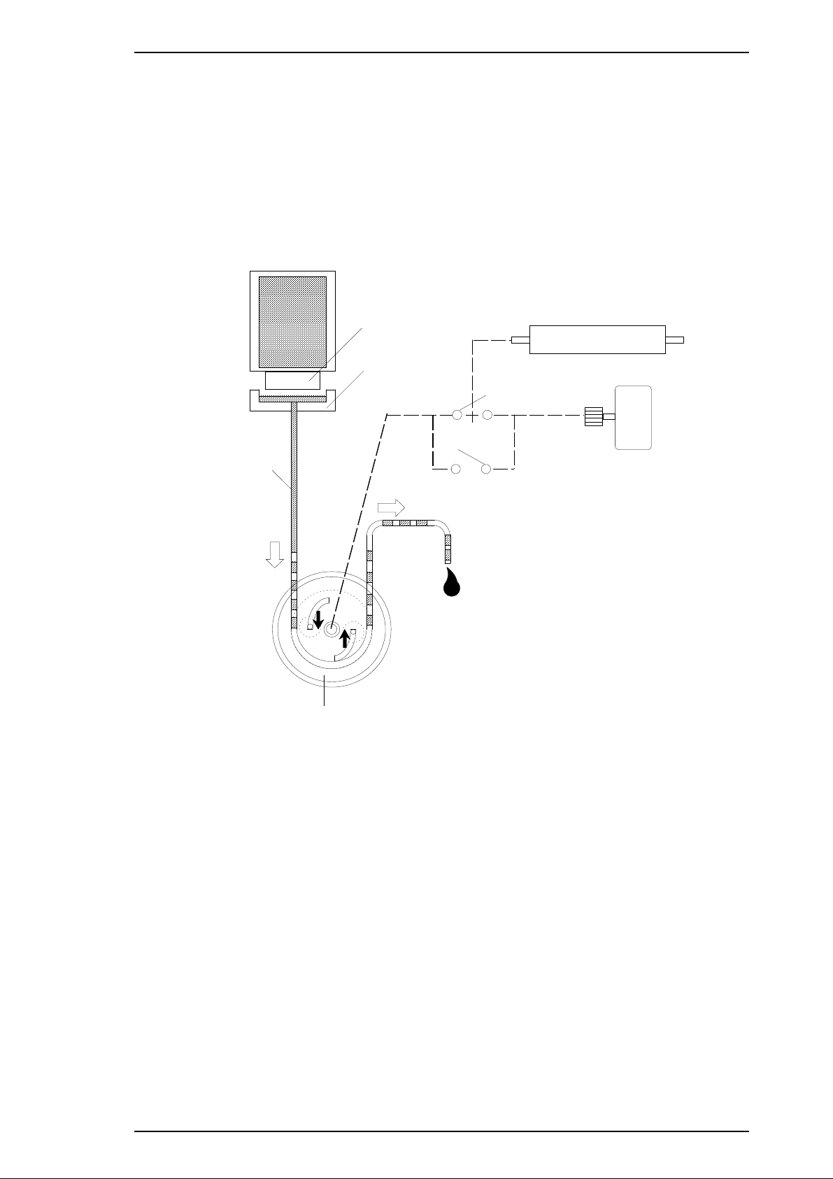
Printhead
Capping Unit
Waste Ink Tube
Pump Roller
Pump On Lever
Pump Off Lever
Platen Roller Unit
PF (Pump) Motor
Ink Cartridge
Stylus Color IIs / Stylus 820 Operating Principles
2.2.5 Ink System
This printer’s ink system is composed of the following mechanisms:
o Ink cartridge
o Pump mechanism
o Cap mechanism
o Waste ink drain tank
o Wiping mechanism
o Carriage lock mechanism
The figure below gives a diagram of the ink system.
Figure 2-10. Ink System Block Diagram
Rev. A 2-11
Page 44
Sus Plate
Paper Pickup Trigger
Pump Off Trigger
Pump On Trigger
Sus Plate
Carriage Lever
1
2
3
4
5
Operating Principles Stylus Color IIs / Stylus 820
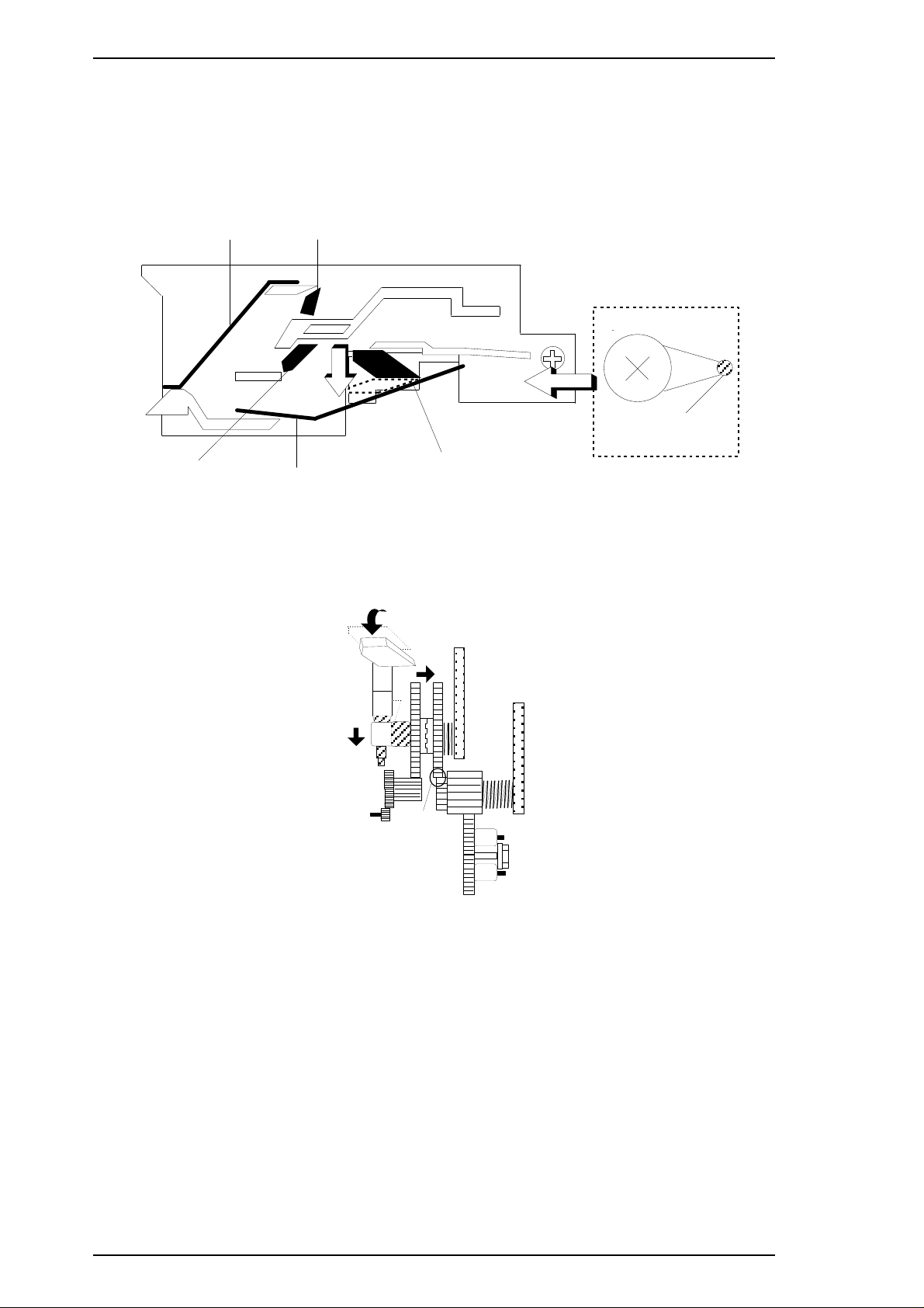
2.2.6 Pump Mechanism
The paper feed motor drives the pump mechanism when the transmission gear is moved to the position where
the paper feed motor engages the pump mechanism gear trains, when the carriage unit is at the ink system
home position. The figure below shows a block diagram of the pump mechanism.
Drive: Trigger Lever Set
Drive: Gear Transmission
Figure 2-12. Pump Transmission Block Diagram
Figure 2-11. Trigger Lever Set
2-12 Rev. A
Page 45

Pump Off Trigger
Pump On Trigger
Pin
Return the pin to
base position
1
2
3
2'
To Pump Off State
Stylus Color IIs / Stylus 820 Operating Principles
Drive: Trigger Lever Reset
Sus Plate
Paper Pickup Trigger
Pump Off Trigger
Sus Plate
Figure 2-13. Trigger Lever Reset
Drive: Gear Transmission
1
Carriage Lever
2
Pump On Trigger
Figure 2-14. Gear Transmission Diagram
Rev. A 2-13
Page 46

No Ink Draining
No Vacuuming
Ink Draining
Vacuuming
Pump Motor (CW): No Pumping
Pump Motor (CCW): Pumping
Operating Principles Stylus Color IIs / Stylus 820
Table 2-8. Pump Mechanism Operation
PF Motor Rotational Direction Operation
Clockwise (CW)
Forward rotation
Counterclockwise (CCW)
Backward rotation
The pump draws ink from the printhead nozzles and drains it to the waste ink drain tank. The printer performs
this operation to eliminate dust or bubbles in the nozzles. Figure 2-11 illustrates pump operation. When the
paper feed drive motor rotates CCW (backward), the pulley pumps in the wheel pump unit rotate in the
direction of the arrow while squeezing the ink tube to push the ink inside the tube out to the waste ink drain
tank.
o Absorption
o False absorption
o Drive transmission change
o Absorption
o False absorption
o Cleaner set
o Drive transmission change
2-14 Rev. A
Figure 2-15. Pump Operation
Page 47

Waste Ink Drain Tank
Cap
Air Tube
Air Valve
Hitting Flag
CR Hitting Flag
Stylus Color IIs / Stylus 820 Operating Principles
2.2.7 Cap Mechanism
The cap mechanism prevents printhead nozzles from drying and keeps bubbles from forming inside the
nozzles while the printer is not in use. The printer performs this operation automatically when print data is not
received. (However, since the power switch is in the primary circuit, it does not allow auto capping when the
user turns the printer off during printing.)
Figure 2-16. Capping Operation
2.2.8 Wiping Mechanism
The wiping mechanism cleans the surface of the printhead nose when the printer is in the ink system
sequence. The wiper drive lever transmits to the pump drive gear via the cam friction roller. A tension spring
in the cam friction roller holds the suface of cam friction roller against the inside of the pump roller.
Lever
Wiper Blade
Internal Flag
Rev. A 2-15
Cam Friction Roller
Figure 2-17. Wiping Mechanism
Page 48

Carriage Lock
Position
Operating Principles Stylus Color IIs / Stylus 820
2.2.9 Carriage Lock Mechanism
The carriage lock mechanism locks the carriage unit when the printer is in the pause state or while it is not
used. The Stylus Color IIs does not use an exclusive mechanism as the carriage lock. (The carriage lock
position is on the engage / disengage rail as shown in the figure below.)
Figure 2-18. Carriage Lock Mechanism
Note:
For servicing, it is very difficult to move the carriage unit to the carriage lock position manually.
Therefore, it is necessary to turn the printer on, set the carriage unit to the lock position, and then
turn the printer off.
2-16 Rev. A
Page 49

PF MOTOR
(Pump Motor)
CR Motor
CR HP Sensor
PE Sensor
Thermistor
No Head Sensor
INK END Sensor
(Firm Wear)
Head Drive Voltage Select
(3-bit ID Code)
Mono./ Color Sensor
Power Drop
Sensor
Printhead
100 VAC
Head Drive Board
ASF Sensor
RCC Power Supply Board
(C160 PSB Board)
+5 VDC
+42 VDC
Main Control Board
(C160 MAIN Board)
+5 VDC
+42 VDC
Stylus Color IIs / Stylus 820 Operating Principles
2.3 OPERATING PRINCIPLES OF THE CIRCUITS
The Stylus Color IIs contains the following circuit board units:
o C160 MAIN Board (main control circuit board)
o C160 PSB/PSE Board (power supply circuit board)
o C160 I/F (exclusive interface board)
In addition to the circuit boards above, part of the printhead drive circuit is built on a separate circuit board
installed in the printhead unit; the printhead unit is attached directly to the carriage unit. The figure below
shows a block diagram of the circuitry.
Rev. A 2-17
Figure 2-19. Block Diagram of the Circuits
Page 50

Operating Principles Stylus Color IIs / Stylus 820
2.3.1 Operating Principles of the Power Supply Circuit
The power supply circuitry for this printer is provided either by the C160 PSB Board (120 VAC) or the C160
PSE Board (220-240 VAC). Both boards are identical in design and functionality, except for components in
the primary circuit that accommodate the specified input voltage. The application of output voltages is
summarized in the table below.
Table 2-9. DC Voltage Distribution
Voltage Application
+42 VDC
Motor drive (carriage and paper feed / pump)
Printhead (through the drive voltage generation circuit)
C160 MAIN Board
+5 VDC
Sensors (home position, paper end, no ink cartridge, head thermistor, etc.)
Control panel, head nozzle selector
The figure below shows a block diagram of the power supply circuit (C160 PSB/PSE). As opposed to Stylus
Color series printers, the power switch for the Stylus Color IIs is in the primary circuit. Therefore, if the user
turns off the printer during printing, the carriage unit stops without capping the nozzles.
Also, this board employs an RCC (ringing choke converter) switching system. This AC voltage is first input
to the filter circuit for higher harmonics absorption, and then input to the rectification and smoothing circuit,
converting it into a DC voltage. This DC voltage is then input to the switching circuit for the switching
operation. Along with the switching operation on the primary side, +42 VDC is generated after passing
through the +42 V line voltage-detection circuit. This +42 VDC output level is stabilized and also is input to
the +5 VDC generation circuit (chopper IC) to generate a stable +5 VDC.
DB1 C11
Full-wave
Rectifier
L1, R1 C1-C4
Filter Circuit
F1
Fuse
Q1
Q2, Q3, IC1
Smoothing
Circuit
Main SW
Circuit
Feedback
Circuit
PC1
PC2
T1
Smoothing
T
Circuit
R
C51
A
N
S
Q81, Q82
Photocoupler
Photocoupler
+42 V Constant
Voltage Control
Circuit
+5 V Creation
Circuit (IC51)
Over Current
Protection Circuit
+42 V Over Voltage
Protection Circuit
ZD52, ZD87
+5 V Over Voltage
Protection Circuit
ZD53, R81
+42 VDC
+5 VDC
Figure 2-20. Power Supply Circuit Block Diagram
2-18 Rev. A
Page 51

Stylus Color IIs / Stylus 820 Operating Principles
1. +5 VDC line over voltage protection circuit
The output voltage level of +5 V line is monitored by Zener diode ZD53. If the voltage level exceeds +6 V,
the status is fed back to the primary switching circuit through photocoupler PC1 to stop the +42 V generation.
2. +5 VDC line over voltage control circuit.
The output current is monitored by a 2-pin detection port in IC51 and fed back to internal comparator; then
the +5 VDC is generated.
3. +42 VDC line over voltage protection circuit
The output level is monitored by Zener diodes ZD52 and ZD87. If the voltage level exceeds +48 V,
photocoupler PC2 is activated; stopping primary switching circuit operation.
4. +42 VDC line constant voltage control circuit
The output level of +42 VDC line is monitored by a detection circuit that consists of Zener diodes ZD51, 81,
82, 83, 84, 85, and 86. This circuit feeds back the output voltage level status through a photocoupler to the
primary switching circuit to control the ON/OFF time of main switching FET Q1 for constant output voltage.
Rev. A 2-19
Page 52

Operating Principles Stylus Color IIs / Stylus 820
2.3.2 Operating Principles of the Main Control Circuit
The main control circuit for this printer is the C160 MAIN Board, which is controlled by the 16-bit CPU
M3772 (IC2), running at 16 MHz. This CPU has a unique architecture capable of handling data on the data
bus at either an 8-bit or 16-bit bus width. Because of this, a 16-bit or 8-bit data bus width-type ROM is used
on this board, increasing the internal processing speed. Additionally, auto refresh for the 1M PS-RAM is
controlled by custom gate array E05B08 ( IC1).
Gate array E05B08 (IC1) manages printhead drive control, the parallel I/F, extension CG board, and the
control panel. The gate array also manages the controls that create the 2-bit signal for the carriage or the paper
feed motor. (The carriage and paper feed motors are controlled by current duty data with micro step control.)
This board also is equipped with EEPROM 93C46 (IC10) to store certain parameters, such as the printer
mechanism control parameters, default setting parameters, as well as the the value in the special counter used
for printhead (ink management) protection.
Because this control board has no lithium battery that allows the printer to keep track of the amount of time
that has elapsed since it was last used, there is no power on cleaning operation for this printer.
EEPROM
Reset IC for
Power System
MACH Serial
(Only JAPAN ver. )
PROM (4M)
(IC3)
(IC10)
93C46
(IC9)
M51955B
PS-RAM (1M)
(IC4)
CE RFRSH
CPU
M3772
(IC2)
CG-RAM (16M)
(IC5)
OEOEOE
Panel
CG-ROM (8M)
(IC6)
E05B08
(IC1)
CG-ROM (16M)
(IC7)
(IC13)
PST592D
Reset IC for
Logic System
To B
To A
CR/PF Drive Signal
Head Common Driver
and Nozzle Selector
From A
From B
C160 MAIN Control Board
Head Common Driver
and Nozzle Selector
Circuit
A2919 (IC12, 16)
CR/PF Drive Circuit
Printhead Unit
SED5629
(U1, U2)
IEEE-1284 Centronics
Mono 64 Nozzles
CMY 60 Nozzles
Figure 2-21. Main Control Circuit Block Diagram
2-20 Rev. A
Page 53

+42 V
+5 V
INT0
CPU (IC2)
+5 V
PST592D
(IC13)
E05B08 (IC1)
RESET
RESET
153
36
1
6
24
M51955B
(IC9)
PA8
Stylus Color IIs / Stylus 820 Operating Principles
2.3.2.1 Reset Circuits
The C160 MAIN Board contains 2 reset circuits: the +5 V monitor reset circuit and the +42 V monitor reset
circuit. The +5 V monitor reset circuit checks the voltage level of the +5 V line, using reset IC PST592D
(IC13), and outputs a reset signal to the E05B08 gate array (IC1) when the voltage level drops below +4.2 V.
The +42 V monitor reset circuit checks the voltage level of the +42 V line, using reset IC M51955B (IC9),
and outputs a reset signal to the CPU. A reset signal is generated when the voltage level drops below +40 V,
and this causes a non-maskable interrupt (NMI).
Figrure 2-22. Reset Circuit Block Diagram
Rev. A 2-21
Page 54

IC2 (CPU: M3772)
74
CR HP
CN8 (1-Pin)
75
PE
CN7 (1-Pin)
81
PE
CN9 (1-Pin)
ID1
ID2
ID3
ID4
CN4 5-pin
CN4 6-pin
CN4 7-pin
CN4 10-pin
96
95
94
97
M/C
CN4 19-pin
76
TH
CN4 18-pin
99
98
AN PORT
Common Drive
Circuit
Operating Principles Stylus Color IIs / Stylus 820
2.3.2.2 Sensor Circuits
The following sensor circuits enable the C162 MAIN Board to monitor printer mechanism status:
HP sensor The photocoupler-type home position (HP) sensor is attached to the surface of the printer
mechanism to detect the carriage home position. A LOW level signal indicates the carriage
is in home position.
PE sensor A mechanical switch-type paper end (PE) sensor is built into the printer mechanism to
determine whether there is paper in the printer or not. A LOW level signal indicates no
paper is loaded.
CO sensor, The cartridge out (CO) sensor is mechnical switch attached to the head unit.
Thermistor A thermistor is attached to the black or CMY printhead unit to monitor its temperature using
the thermistor’s resistance value (at 25° Cor77°F, approximately 10K Ω). The CPU
changes the printhead drive signal’s pulse width (PWM control) based on the temperature
level.
M/C sensor The circuit pattern is decided as follows:
q Black head: LOW
q CMY head: HIGH
When the printhead is installed in the carriage unit, the control board recognizes the current
head automatically.
ID sensor There are four ID ports in the head unit. When the printer is turned on, the control circuit
decodes this ID data and outputs it automatically with the correct voltage. (During servicing,
it is not necessary to install a resistor array onto the control board as with previous printers.)
ASF sensor If the user changes the paper select lever to manual feed mode, the ASF sensor monitors this
and changes the paper feed sequence.
Figure 2-23. Sensor Circuit Block Diagram
2-22 Rev. A
Page 55

Stylus Color IIs / Stylus 820 Operating Principles
2.3.2.3 Carriage Motor Driver Circuit
Carriage motor driver IC A2919 (IC12) outputs a constant current to drive the carriage motor. Gate
array E05B08 (IC1) decides the motor phase and speed, and then sends a signal to the carriage motor
driver IC using a 2-bit signal transmission line. (In the Stylus Color printer, 4-bit serial data was
transmitted from the gate array to the driver IC.)
The carriage motor is controlled using a 1W1-2 phase method. 1W1-2 phase is
Stylus Color printer, the carriage motor was controlled using 2W1-2 phase.) The table below shows the
motor drive method along with the micro steps.
1
⁄4the 2-2 phase. (In the
Table 2-10. Motor Drive Method (Clockwise Direction)
Step
1
^ +1/3 +1
^
^
2
^
^
^
3
^
^
^
4
Phase A Phase B
+2/3 +2/3
0+1
–1/3 +1
–2/3 +2/3
–1 +1/3
–1 0
–1 –1/3
–2/3 –2/3
–1/3 –1
0–1
+1/3 –1
+2/3 –2/3
^
^
^
Note: One feature of driver IC A2919 is that it can gain constant torque by small movements of the
carriage motor if 1/3 × 1TRIP (TRIP = established current). Therefore, the driver sequence
reflects that coefficient in the above table.
Also, the phase drive signal uses only two ports of IC A2919. The table below shows the connection
between the input and output signals.
+1 –1/3
+1 0
+1 +1/3
Table 2-11. Connection Between Input and Output Signals
Phase (Input Port) OUT A OUT B
H HL
LLH
Note:
As shown above, two output signals are decided by only one input signal.
Rev. A 2-23
Page 56

Operating Principles Stylus Color IIs / Stylus 820
The figure below shows a block diagram of the carriage motor, and the Table 2-12 lists the connection
between current control value and output current.
VREF2
I12
+5 V
VREF1
I02
IC1 (GA)
IC2 (CPU)
Phase A or /A
Phase B or /B
VREF0
VREF1
VREF2
P56
P57
BPTO0
BPTO1
BPTO2
BPT12
141
142
143
A2919
3
PHASE2
11
PHASE1
10
9
8
7
6
5
I11
I01
Figure 2-24. Carriage Motor Driver Circuit Block Diagram
Table 2-12. Connection between Current Value and Input Signal
I01 (I02)
I11 (I12) Output Current
L
H
L
H
L 1 TRIP (100%)
L 2/3 TRIP (67%)
H 1/3 TRIP (33%)
H 0 (0%)
The micro step method is performed by PWM control in the driver IC, as shown below.
-`
`
A -A
Full Bridge
Bi-poler
Phase 1 Phase 2
PWM1 PWM2
I11 I01
Frequency is decided by the
external CR circuit.
B -B
Full Bridge
Bi-poler
I12
I02
Vref
Output Waveform
Figure 2-25. A2919 Internal Block Diagram
2-24 Rev. A
Page 57

M
A
/A
B
/B
23 17
20
14
21
15
16
RC
1
2
RS (Current Monitor)
RC
RS
Stylus Color IIs / Stylus 820 Operating Principles
2.3.2.4 Paper Feed Motor Driver Circuit
The paper feed motor for this printer drives the following mechanisms:
o Paper feed mechanism
o Paper pickup mechanism
o Pump mechanism
Driver IC A2919 (IC16) drives the paper feed motor by constant current. Its principle of operation is the same
as for the carriage motor driver circuit. (However, the drive method is different from the carriage motor’s.)
Table 2-13 lists the motor drive method in the CW direction.
Table 2-13. Motor Drive Method (CW Direction)
Step Phase A Phase /A Phase B Phase /B
1 –+–+
2
3
4
Note: The figure below shows a circuit diagram for the paper feed motor and motor driver IC.
+––+
+–+–
–++–
Figure 2-26. PF Motor Driver Circuit Diagram
Rev. A 2-25
Page 58

Operating Principles Stylus Color IIs / Stylus 820
2.3.2.5 Printhead Driver Circuit
The printhead driver circuit for this printer is composed of the following:
o Common driver circuit (trapezoidal drive pulse generation)
o Head driver circuit (nozzle control built on the printhead)
SED5619D, the 64-bit thermal head driver in the head drive circuit on the carriage, is used as a nozzle selector
to drive printhead nozzles selectively. Print data is converted into serial data by gate array E05B08 (IC1) and
is output from port SO (pin 13) to the black and CMY head driver circuits. Head driver SED5619D latches
head data when gate array E05B08 outputs the LATCH signal, and the latched data becomes 64-bit parallel
data for the black head or 60-bit parallel data for the CMY head. One bit corresponds to each nozzle.
When data transfer and nozzle selection is complete, gate array E05B08 outputs the common drive pulses
(CHG (MCHG) signal, DCHG1 signal, DCHG2 signal, DCHG3 signal) to the common driver circuit. The
common driver circuit then generates the trapezoidal pulse and applies it to the printhead as a common drive
pulse. Then, the nozzle selected by the head data is activated to eject ink.
Normal Mode
IC1 (GA)
IC2 (CPU)
HCLK
LAT
SI
MCHG
CCHG
DCHG1
DCHG2
DCHG3
PWM
AN2
M/C
TH
ID4
ID3
ID2
ID1
CO
132
139
131
138
137
133
134
135
136
96
76
99
97
94
95
96
73
Common Driver
Circuit
Common
SED5619
64-bit data
Printhead
Figure 2-27. Head Driver Circuit Block Diagram
The normal mode for the Stylus Color IIs operates differently from the normal mode for other Stylus printers.
The printer uses normal mode printing only when the user selects 360 dpi printing with the custom printer
driver. (Refer to Section 2.2.2. ) The figure below shows the head drive waveform for normal mode.
Note:
If single firing is performed, printer outputs only wave # 1.
B
#1
#2
C
D
E
A
F
G
A: 1st charge, B: 1st hold, C: 1st discharge
D: 2nd hold, E: 2nd discharge
F: 3rd discharge, G: pause
Figure 2-28. Head Driver Waveform for Normal Mode
2-26 Rev. A
Page 59

ID1
GND2 GND CLK
ID2
GND2
SI
GND
TH
IE ID4 CO
COM
M/C
LAT
FG
COM ID3
GND
VDD
Stylus Color IIs / Stylus 820 Operating Principles
The electrical pole configuration on the printhead unit is as follows:
Figure 2-29. Printhead Electrical Pole Configuration
SI Signal: For transmitting 64-bit serial data to the SED5619D
LAT: The latch trigger for 64-bit serial data in the driver IC (SED5619D)
CLK: The standard trigger for driving serial transmission
Note:
Refer to Section 2.3.2.2 about the other signals.
Rev. A 2-27
Page 60

Chapter 3 Disassembly and Assembly
Table of Contents
3.1 OVERVIEW 3-1
3.1.1 Precautions for Disassembling the Printer . . . . . . . . . . . . . . . . . . . . . . 3-1
3.2 DISASSEMBLY AND ASSEMBLY 3-2
3.2.1 Upper Case Removal . . . . . . . . . . . . . . . . . . . . . . . . . . . . . . . . . . . . . . . . 3-2
3.2.2 C160 Main Board Removal . . . . . . . . . . . . . . . . . . . . . . . . . . . . . . . . . . . . 3-3
3.2.3 C160 I/F Board Removal . . . . . . . . . . . . . . . . . . . . . . . . . . . . . . . . . . . . . . 3-4
3.2.4 C160 PSB/PSE Board Removal . . . . . . . . . . . . . . . . . . . . . . . . . . . . . . . . 3-5
3.2.5 M-4C10 Printer Mechanism Removal . . . . . . . . . . . . . . . . . . . . . . . . . . . 3-6
3.2.6 Printer Mechanism Disassembly . . . . . . . . . . . . . . . . . . . . . . . . . . . . . . . 3-7
3.2.6.1 Carriage Unit Removal . . . . . . . . . . . . . . . . . . . . . . . . . . . . . . . . 3-7
3.2.6.2 ASF Unit Removal . . . . . . . . . . . . . . . . . . . . . . . . . . . . . . . . . . . . 3-9
3.2.6.3 PE Sensor Removal. . . . . . . . . . . . . . . . . . . . . . . . . . . . . . . . . . . 3-9
3.2.6.4 Pick Up Roller Unit Removal . . . . . . . . . . . . . . . . . . . . . . . . . . 3-10
3.2.6.5 Carriage Home Position Sensor Removal . . . . . . . . . . . . . . . 3-10
3.2.6.6 Paper Feed Roller Unit Removal . . . . . . . . . . . . . . . . . . . . . . . 3-11
3.2.6.7 Carriage Motor Removal . . . . . . . . . . . . . . . . . . . . . . . . . . . . . . 3-11
3.2.6.8 Head Cleaner Replacement Removal . . . . . . . . . . . . . . . . . . . 3-12
3.2.6.9 Pump Unit Removal. . . . . . . . . . . . . . . . . . . . . . . . . . . . . . . . . . 3-13
3.2.6.10 Paper Feed Motor Removal . . . . . . . . . . . . . . . . . . . . . . . . . . 3-14
Rev. A 3-i
Page 61

LIST OF FIGURES
Figure 3-1. Upper Housing Removal . . . . . . . . . . . . . . . . . . . . . . . . . . . . . . . . 3-2
Figure 3-2. C160 Main Control Board Removal . . . . . . . . . . . . . . . . . . . . . . . 3-3
Figure 3-3. ASF Sensor Removal. . . . . . . . . . . . . . . . . . . . . . . . . . . . . . . . . . . 3-3
Figure 3-4. FFC Cable Removal . . . . . . . . . . . . . . . . . . . . . . . . . . . . . . . . . . . . 3-4
Figure 3-5.C160 I/F Board Removal. . . . . . . . . . . . . . . . . . . . . . . . . . . . . . . . . 3-4
Figure 3-6. C160 PSB/PSE Board Removal . . . . . . . . . . . . . . . . . . . . . . . . . . 3-5
Figure 3-7. Printer Mechanism Removal. . . . . . . . . . . . . . . . . . . . . . . . . . . . . 3-6
Figure 3-8. PG Lever and Tension Coil Removal . . . . . . . . . . . . . . . . . . . . . . 3-7
Figure 3-9. Parallelism Adjust Lever Removal. . . . . . . . . . . . . . . . . . . . . . . . 3-8
Figure 3-10. Carriage Unit Removal . . . . . . . . . . . . . . . . . . . . . . . . . . . . . . . . 3-8
Figure 3-11. ASF Unit Removal . . . . . . . . . . . . . . . . . . . . . . . . . . . . . . . . . . . . 3-9
Figure 3-12. PE Sensor Removal. . . . . . . . . . . . . . . . . . . . . . . . . . . . . . . . . . . 3-9
Figure 3-13. Pick Up Roller Unit Removal. . . . . . . . . . . . . . . . . . . . . . . . . . . 3-10
Figure 3-14. Carriage Home Position Sensor. . . . . . . . . . . . . . . . . . . . . . . . 3-10
Figure 3-15. Paper Feed Roller Unit Removal . . . . . . . . . . . . . . . . . . . . . . . 3-11
Figure 3-16. Carriage Motor Removal . . . . . . . . . . . . . . . . . . . . . . . . . . . . . . 3-11
Figure 3-17. Head Cleaner Replacement. . . . . . . . . . . . . . . . . . . . . . . . . . . . 3-12
Figure 3-18. Cap Unit Removal . . . . . . . . . . . . . . . . . . . . . . . . . . . . . . . . . . . 3-13
Figure 3-19. Pump Unit Releasing . . . . . . . . . . . . . . . . . . . . . . . . . . . . . . . . . 3-13
Figure 3-20. Pump Unit Removal . . . . . . . . . . . . . . . . . . . . . . . . . . . . . . . . . . 3-14
Figure 3-21. Paper Feed Motor Removal. . . . . . . . . . . . . . . . . . . . . . . . . . . . 3-14
Figure 3-22. Head Data Indication . . . . . . . . . . . . . . . . . . . . . . . . . . . . . . . . . 3-20
3-ii Rev. A
Page 62
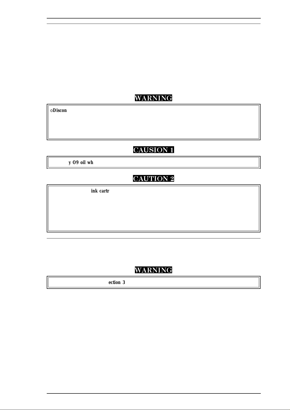
Stylus Color IIs / Stylus 820 Disassembly and Assembly
3.1 OVERVIEW
This section describes procedures for disassembling the main components of the printer. Unless otherwise
specified, disassembled units or components can be reassembled by reversing the disassembly procedure.
Therefore, no assembly procedures are included. Precautions for any disassembly or assembly procedure are
described under the heading “Disassembly/Assembly Points.” Adjustments required after assembling the unit
are described under the heading “Required Adjustments.”
3.1.1 Precautions for Disassembling the Printer
See the precautions below when disassembling the printer.
WARNING
oDisconnect the power cable before disassembling or assembling the printer.
oWear goggles to protect your eyes from ink. If ink gets in your eye, flush it with fresh water
and see a doctor immediately.
oIf ink comes into contact with your skin, wash it off with soap and water. If irritation
occurs, contact a physician.
CAUSION 1
oUse only O9 oil when lubricating the carriage guide shaft.
CAUTION 2
oNever remove the ink cartridge from the carriage unless manual instructions specify to
do so.
oWhen transporting the printer after installing the ink cartridge, be sure to pack the
printer for transportation without removing the ink cartridge.
oUse only recommended tools for disassembling, assembling, or adjusting the printer.
oApply lubricants and adhesives as specified. (See Chapter 6.)
oMake specified adjustments when you disassemble the printer. (See Chapter 4.)
3.2 DISASSEMBLY AND ASSEMBLY
This section consists of the subheads shown in the diagram below. See the exploded view of the printer in the
Appendix, if necessary.
WARNING
Follow the precautions in Section 3.1.1 when disassembling the printer.
This section consists of the subheads shown in the diagram(next page).
Rev. A 3-1
Page 63

Disassembly and Assembly Stylus Color IIs / Stylus 820
START
Upper Case
Removal
3.2.1 Page 3-2
PE Sensor
Removal
3.2.6.3 Page 3-9
Pickup Roller
Removal
3.2.6.4 Page 3-10
Head Cleaner
Replacement
3.2.6.8 Page 3-12
C160 Main Board
Removal
3.2.2 Page 3-3
ASF Unit
Removal
3.2.6.2
CRHP Sensor
Removal
3.2.6.5 Page 3-10
3.2.6.9 Page 3-13
Page 3-9
Pump Unit
Removal
C160 I/F Board
Removal
3.2.3 Page 3-4
Carriage Unit
Removal
3.2.6.1 Page 3-7
Paper Feed Roller
Unit Removal
3.2.6.6 Page 3-11
Paper Feed Motor
Removal
3.2.6.10 Page 3-14
C160 PS Board
Removal
3.2.4 Page 3-5
M-4C10 Mechanism
Removal
3.2.5 Page 3-6
3.2.1 Upper Case Removal
1.1.
Remove the sheet guide from main unit. Then remove 2 CBB (M4 × 11) screws securing the upper case
to the bottom case.
2.
Open the front cover; then remove 2 CBB (M4 × 11) screws securing the upper case to the bottom case.
3. Remove 1 small screw securing the ASF knob to the lever.
4. Remove the upper case by lifting the front side.
DISASSEMBLY/ASSEMBLY POINT
When you move the carriage unit manually to remove 1 screw(*), push it once toward the right,
and move to the left side .
CBB(M4X11)
(*)
CBB(M4X11)
CBB(M4X11)
CBB(M4X11)
CBB(M4X11)
Small Screw
Figure 3-1. Upper Case Removal
3-2 Rev. A
Page 64
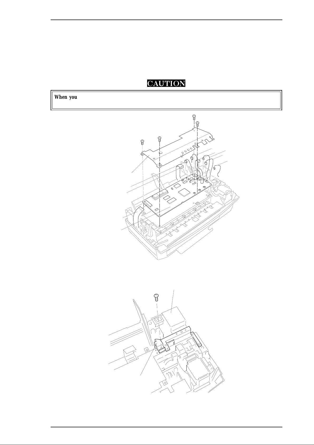
CBB(M3x6)
CBB(M3x6)
CBB(M3x6)
CBB(M3x6)
Shield Plate
CN1
CN8
CN7
CN4
CN3
CN5
CN6
C160 Main Board
CN9
CBB(M3x6)
C160 PSB/PSE Board
ASF Sensor Holder
Stylus Color IIs / Stylus 820 Disassembly and Assembly
3.2.2 C160 MAIN Control Board and ASF Sensor Removal
1. Remove the upper case (see Section 3.2.1).
2.
Remove 4CBB (M3×6) screws attaching the shield frame to the C160 MAIN Board.
3. Remove 7 connectors (CN1, CN8, CN7, CN4, CN3, CN5, CN6) on the main board. (Push CN6 down to
release cable on main board.) Then remove the C160 Main Control Board.
4. Remove a CBB (M3x6) screw fixing a ASF Sensor holder to printer mechanism.
CAUTION
When you replace the C160 MAIN Board, reset the EEPROM and perform the required
adjustments. (See Chapter 4.)
Figure 3-2. C160 Main Control Board Removal
Figure 3-3. ASF Sensor Removal
Rev. A 3-3
Page 65

CBB(M3x10)
CPS(M3x10)
CPS(M3x10)
Grounding Plate
Disassembly and Assembly Stylus Color IIs / Stylus 820
5.
Remove 3 CPS (M3×6) screws fixing the board frame to the mechanism and 1 CPS (M3x6) screw fixing
the metal stay between the board frame and the side(right) frame. Then remove the metal stay.
6.
Remove 2 CPS (M3×6) screws fixing the transpearency plate, then remove it.
7. Release the 3 hooks securing the FFC cable to the board frame then remove the board frame.
Metal stay
Transpearency plate
Figure 3-4. Board Frame and Metal Stay Removal
CPS(M3x6)
CPS(M3x6)
CPS(M3x6)
1
0
Board Frame
3.2.3 C160 I/F Board Removal
1. Remove the upper case (see Section 3.2.1).
2.
Remove 2 CPS (M3×6) screws and 1 CBB (M3×10) securing the C106 I/F Board to the mechanism and
bottom case.
3. Disconnect CN1 on this board; then remove it by lifting it up.
Figure 3-5. C160 I/F Board Removal
3-4 Rev. A
Page 66
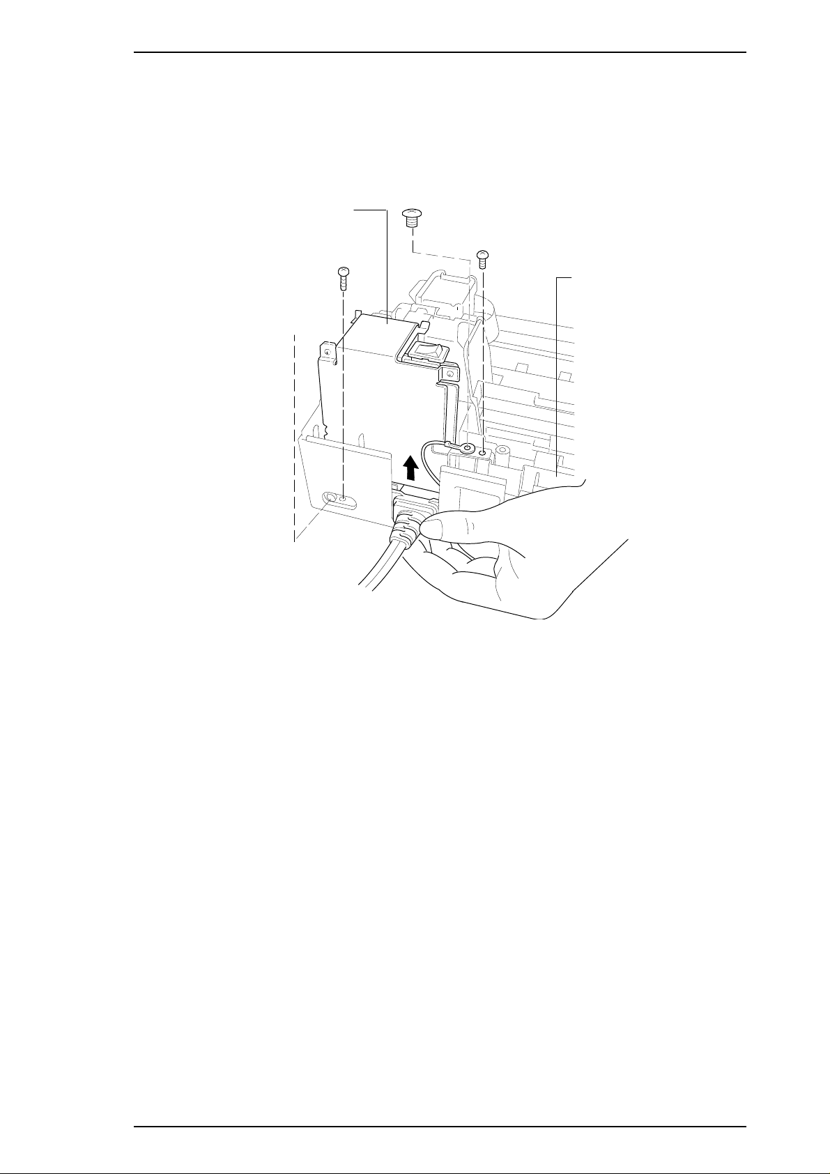
CPS(M3x6)
CBB(M3x10)
Big Screw
CBB(M3x10)
C160 PSB/PSE Board
Grounding Plate
Stylus Color IIs / Stylus 820 Disassembly and Assembly
3.2.4 C160 PSB/PSE Board Removal
1. Remove the upper case (see Section 3.2.1).
2.
Remove 1 CBB (M3×10) screw securing the power supply board to the lower case, 1 CPS (M3×6)
screw securing the board frame to the grounding plate, 1 CBB (M3x10) screw fixing the board frame
and 1 big screw securing the board frame to the lower case via the grounding plate.
Figure 3-6. C160 PSB/PSE Board Removal
Rev. A 3-5
Page 67

CBB(M3x11)
CBB(M3x11)
CBB(M3x11)
CBB(M3x11)
M-4C10 Printer Mechanism
Disassembly and Assembly Stylus Color IIs / Stylus 820
3.2.5 M-4C10 Printer Mechanism Removal
1. Remove the upper case (see Section 3.2.1).
2. Remove the C160 MAIN Board (see Section 3.2.2).
3. Remove the C160 I/F Board (see Section 3.2.3).
4. Remove the C160 power supply board (see Section 3.2.4).
5.
Remove 4 CBB (M4x11) screws securing the printer mechanism to the lower case.
CAUTION
When you replace the printer mechanism, perform the required adjustments. (See Chapter 4.)
Figure 3-7. Printer Mechanism Removal
3-6 Rev. A
Page 68

Stylus Color IIs / Stylus 820 Disassembly and Assembly
3.2.6 Printer Mechanism Disassembly
The procedures described in this section explain how to remove components within the printer mechanism.
3.2.6.1 Carriage Unit Removal
1. Remove the printer mechanism (see Section 3.2.6).
2. Remove the blue PG lever.
3. Remove the tension coil securing the parallelism bushing to the side frame.
CAUTION
Use only O9 oil when lubricating the carriage guide shaft.
PG Lever
2
0
Tension Spring
Figure 3-8. PG Lever and Tension Coil Removal
1
1
Rev. A 3-7
Page 69

Parallelism Adjust Lever
Lever Knob
1
2
Disassembly and Assembly Stylus Color IIs / Stylus 820
4. Remove the parallelism adjust lever by rotating it toward front while pulling the lever knob.
Figure 3-9. Parallelism Adjust Lever Removal
5. Remove the timing belt while pressing the pulley holder; then remove the carriage unit along with the
carriage guide shaft.
Pulley Holder
1
Figure 3-10. Carriage Unit Removal
3-8 Rev. A
Page 70

2
1
1
ASF Unit
CAUTION
ASF Unit
PE Sensor Actuator
Stylus Color IIs / Stylus 820 Disassembly and Assembly
3.2.6.2 ASF Unit Removal
1. Remove the printer mechanism (see Section 3.2.5).
2. Press down the tab on the left side; then pull the ASF unit toward you.
3. Press the tab on the right side; then remove the ASF unit.
CAUTION
When you remove the ASF, be extremely careful of the PE sensor. Pull the top of the ASF unit
toward the front of the mechanism to clear the PE sensor.
Figure 3-11. ASF Unit Removal
3.2.6.3 PE Sensor Removal
1. Remove the printer mechanism (see Section 3.2.5).
2. Remove the ASF unit (see Section 3.2.6.2).
3. Disconnect CN7 on the C160 MAIN Board, then remove the PE sensor.
PE Sensor Actuator
1-Screw
Figure 3-12. PE Sensor Remopval
Rev. A 3-9
Page 71

0
1
2
Pick Up Roller Unit
Shaft Holder
Washer
Tension
Spring
CPS(M3x6)
Carriage Home
Position Sensor
Carriage Motor
Disassembly and Assembly Stylus Color IIs / Stylus 820
3.2.6.4 Pickup Roller Unit Removal
1. Remove the printer mechanism (see Section 3.2.5).
2. Remove the ASF unit (see Section 3.2.6.2).
3. Remove the PE sensor (see Section 3.2.6.3).
4. By rotating it, remove 1 shaft holder securing the roller shaft to the frame.
5. Remove the pickup roller unit, referring the following illustration.
Figure 3-13. Pick Up Roller Unit Removal
3.2.6.5 Carriage Home Position Sensor Removal
1. Remove the printer mechanism (see Section 3.2.5).
2. Disconnect the CN8 on the C160 MAIN Board.
3.
Remove the 2 CPS (M3x6) screws securing the metal stay to the printer mechanism.
Figure 3-14. Carriage Home Position Sensor Removal
3-10 Rev. A
Page 72

Paper Feed Roller Unit
Front Frame
CPS(M3x6)
Stylus Color IIs / Stylus 820 Disassembly and Assembly
3.2.6.6 Paper Feed Roller Unit Removal
1. Remove the printer mechanism (see Section 3.2.5).
2. Remove the carriage unit (see Section 3.2.6.1).
3. Remove the carriage home position sensor (see Section 3.2.6.5).
4. Remove the tension spring holding the tension roller assembly to the sub frame.
5.
Remove 2 CPS (M3x6) screws securing the front frame to the printer mechanism.
6. Remove the paper feed roller unit.
Figure 3-15. Paper Feed Roller Unit Removal
3.2.6.7 Carriage Motor Removal
1. Remove the printer mechanism (see Section 3.2.5).
2. Remove the carriage unit (see Section 3.2.6.1).
3. Remove the carriage (CR) motor.
Note:
When you remove the CR motor, be sure to keep the washer on the CR motor gear.
CAUTION
When you remove or remount the CR motor, be careful of the post at both the top and bottom of
the motor. If this post is broken, the motor will not seat correctly and can move during printing.
Carriage Motor
Motor Holder
Figure 3-16. Carriage Motor Removal
Rev. A 3-11
Page 73

0
1
Head Cleaner
Hook
Platen
Disassembly and Assembly Stylus Color IIs / Stylus 820
3.2.6.8 Head Cleaner Replacement
1. Remove the printer mechanism (see Section 3.2.5).
2. Remove the front frame (see Section 3.2.6.6).
3. Use tweezers to unhook the head cleaner.
Figure 3-17. Head Cleaner Replacement
CAUTION
o Never touch the head cleaner with your bare hands.
o When attaching the head cleaner, wear gloves and use clean tweezers to handle it.
3-12 Rev. A
Page 74

White Tube
CPS(M3x6)
1
CPS(M3x6)
CPS(M3x6)
Black Holder
CPS(M3x12)
CPS(M3x8)
Hexagonal Screw
Tension Spring
Shift
2
Push
Stylus Color IIs / Stylus 820 Disassembly and Assembly
3.2.6.9 Cap Unit Removal
1. Remove the printer mechanism (see Section 3.2.5).
2. Remove the front frame (see Section 3.2.6.6).
3. Remove 1 CPS (M3x6) screw securing the cap unit to the lower frame.
Figure 3-18. Pump Unit Removal
4. Remove 1 CPS (M3x6) screw securing the black holder to the frame
5. Remove the white tube connecting the cap unit to the pump unit.(Be careful an ink leak when you
remove this ink tube.)
6.
Remove 3 screws — 1 CPS (M3x6), 1 CPS (M3x12), and 1 CPS (M3x8) — securing the pump unit to
the main frame.
7. Release a tension spring securing the paper pick up trigger holder to the pump mechanism.
Notes:
1. When you remove the pump unit, be sure to keep the washer, located behind the pump.
2. When you remove the pump unit, do not lose the pin in the pin holder.
Figure 3-19. Pump Unit Releasing
Rev. A 3-13
Page 75
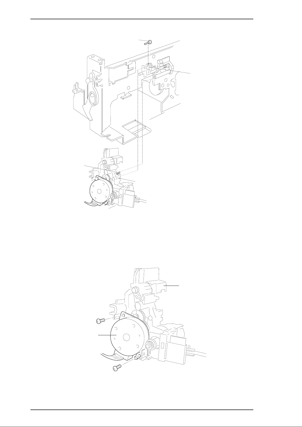
Pin
HOLE
Pin Holder
Pump Unit
Pin
Disassembly and Assembly Stylus Color IIs / Stylus 820
Figure 3-20. Pin Position
3.2.6.10 Paper Feed Motor Removal
1. Remove the printer mechanism (see Section 3.2.5).
2. Remove the pump unit. (see Section 3.2.6.9).
3.
Remove the 2 CBB (M3x10) screws securing the paper feed motor to the motor frame.
CBB(M3x10)
PF Motor
CBB(M3x10)
Pump Unit
Figure 3-21. Paper Feed Motor Removal
3-14 Rev. A
Page 76

Chapter 4 Adjustment
Table of Contents
4.1 OVERVIEW 4-1
4.1.1 Destination Data Writing Operation. . . . . . . . . . . . . . . . . . . . . . . . . . . . . 4-2
4.1.2 Bi-D (Bidirectional Printing) Alignment Adjustment . . . . . . . . . . . . . . . 4-3
4.1.3 Head Angle Adjustment (Black Head only) . . . . . . . . . . . . . . . . . . . . . . 4-5
4.1.4 Platen Gap Adjustment. . . . . . . . . . . . . . . . . . . . . . . . . . . . . . . . . . . . . . . 4-7
4.1.5 EEPROM Reset Operation . . . . . . . . . . . . . . . . . . . . . . . . . . . . . . . . . . . . 4-8
List of Figures
Figure 4-1. Nozzle Confirmation Pattern . . . . . . . . . . . . . . . . . . . . . . . . . . . . . 4-3
Figure 4-2. Head Angle Pattern (Angle Correct) . . . . . . . . . . . . . . . . . . . . . . . 4-5
Figure 4-3. Head Angle Pattern (Angle Incorrect). . . . . . . . . . . . . . . . . . . . . . 4-5
Figure 4-4. Angle Lever Operation . . . . . . . . . . . . . . . . . . . . . . . . . . . . . . . . . . 4-6
Figure 4-5. PG Lever Operation . . . . . . . . . . . . . . . . . . . . . . . . . . . . . . . . . . . . 4-7
Figure 4-6. Confirmation Method . . . . . . . . . . . . . . . . . . . . . . . . . . . . . . . . . . . 4-7
List of Tables
Table 4-1. Required Adjustments . . . . . . . . . . . . . . . . . . . . . . . . . . . . . . . . . . . 4-1
Table 4-2. Gap and Adjustment Direction . . . . . . . . . . . . . . . . . . . . . . . . . . . . 4-2
Rev. A 4-i
Page 77

Stylus Color IIs / Stylus 820 Adjustments
4.1 OVERVIEW
This section describes adjustments required when the printer is disassembled and assembled after repair.
WARNING
oAfter removing an ink cartridge, always install a new cartridge immediately. During adjustments
and testing, use cartridges designed exclusively for service
(Monochrome: 1023206, CMY: 1023207).
oOnly adjust the black head angle when you perform the head angle adjustment.
Table 4-1. Required Adjustments
Service Performed Adjustment Needed
When replacing the
M-4C10 Printer Mechanism
When replacing C160 MAIN Board
When replacing or disassembling the
carriage unit
1. Bi-D Adjustment (see Section 4.1.2).
1. EEPROM Reset Operation (see Section 4.1.5).
2. Destination Data Registration (see Section 4.1.1).
2. Bi-D Alignment Adjustment (see Section 4.1.2).
1. Head Angle Adjustment (see Section 4.1.3).
2. Platen Gap Adjustment (see Section 4.1.4).
Rev. A 4-1
Page 78

Adjustments Stylus Color IIs / Stylus 820
4.1.1 Destination Data Writing Operation
The setup value that specifies the printer destination (for character generation and panel default settings) is
stored in the EEPROM on the C160 MAIN Board. Therefore, this setup value must be written into the
EEPROM when the main board or EEPROM chip is replaced.
CAUTION
Before writing the destination data writing, set the interface to parallel.
1. Connect the PC to the target printer using a parallel interface cable and turn the printer on.
2. Execute BASIC on the PC, and run the program HUDSON.BAS. You see the following menu:
Stylus / MJ Program H90E00E
***** Model *****
1. Stylus Color IIs
2. Stylus 820
3. MJ-500C
7. END
3. When the main menu appears, choose the product name by typing 1 or 2 and Enter.
4. You see the following menu.
Stylus / MJ Program H90E00E
***** Customer *****
1. EAI, EAI (Latin America), EAL, ESP, ETT
2. EUL, EDG, EFS, EIS, EIB, EUL (North Europe), EUL (Middle East), EHK
3. [EDG (NLSP)]
4. Russia
Slect Menu ?
5. Select your country.
6. If you have completed all your selections, turn off the printer.
Note:
It is not necessary to turn off the printer if you want to perform the other adjustments.
4-2 Rev. A
Page 79

Stylus Color IIs / Stylus 820 Adjustments
4.1.2 Bi-D (Bidirectional Printing) Alignment Adjustment
Bidirectional alignment is required when the printer mechanism, main board, or printhead (board) is replaced.
Performing this adjustment determines a compensation value to rectify any deviation in the print position.
This deviation could be caused by the different print speeds, which are due to tolerances in the mechanical
components, or to differences in print timing between odd-numbered lines and even-numbered lines in
bidirectional printing. The printer stores the compensation data in the EEPROM on the C160 MAIN Board
and refers to this data when performing bidirectional printing.
1. Perform steps 1 to 5 in Section 4.1.1. Then you see the following menu:
Stylus Program * H90E00E
Model : Stylus Color IIs
Customer : EAI, EAI (Latin America), EAL, ESP, ETT
1. Ink discharge (Black)
2. Ink discharge (Color)
3. Head Angle Adjustment
4. Bi-D Adjustment (Bi-d Center -15)
5. A4 check pattern (Black)
6. A4 check pattern (Color)
7. Envelope
8. Index Card / Post Card
0. Change Customer & Model / END
13. BLACK Ink Counter Reset
14. COLOR Ink Counter Reset
Select Menu ?
2. Choose “Bi-D Adjustment” by typing 4 and ENTER. You see the following menu:
BLACK head ———- 1
COLOR head ———- 2
Select Menu ?
3. Choose the type of head currently installed on the main unit. The printer prints the Bi-D pattern with the
current value. (The next value will automatically appear.) Also, the display will change as shown below:
INPUT ADJUST N0. (IF OK INPUT Y & RETURN) ?
ADJUST RANGE (from -36 to 36)
Note:
You also can find any clogged nozzle by printing the sample pattern below.
1-pin
64-pin
Figue 4-1. Nozzle Configuration Pattern
Rev. A 4-3
Page 80

Adjustments Stylus Color IIs / Stylus 820
4. If the sample print does not vertically align both odd- and even-numbered lines, enter a compensation
value in the range from −36 to +36.
o Positive compensation value: Shifts the 2nd line to the left
o Negative compensation value: Shifts the 2nd line to the right
When the sample print becomes vertically aligned for both lines, press Y and ENTER; this returns you
to the main menu.
6. Choose “END” by typing 0 and ENTER. The initial message appears on the display. If you have
completed all the adjustments you want to make, turn off the printer.
Note:
It is not necessary to turn off the printer if you want to perform the other adjustments.
4-4 Rev. A
Page 81

Stylus Color IIs / Stylus 820 Adjustments
4.1.3 Head Gap Adjustment (Black and Color Head)
The head gap adjustment is required when the printer mechanism, main board, or printhead (board) is replaced
or diassembled. This adjustment calibrates the head drive timing between the black and color head. If this
adjustment is not made, the vertical alignment will not be completed.
Note:
1. Perform steps 1 to 5 in Section 4.1.1. Then you see the following menu:
Use only a black head unit when you perform the head angle adjustment. Also, use only
a normal plain paper, because the type of black ink is using the slow penetration type.
Stylus Program * H90E00E
Model : Stylus Color IIs
Customer : EAI, EAI (Latin America), EAL, ESP, ETT
1. Ink discharge (Black)
2. Ink discharge (Color)
3. Head Angle Adjustment
4. Bi-D Adjustment (Bi-d Center -15)
5. A4 check pattern (Black)
6. A4 check pattern (Color)
7. Envelope
8. Index Card / Post Card
0. Change Customer & Model / END
13. BLACK Ink Counter Reset
14. COLOR Ink Counter Reset
Select Menu ?
2. Choose “Head Angle Adjustment” by typing 3 and ENTER. Then the printer prints an angle
adjustment check pattern. If the head angle is correct you see the following angle adjustment pattern.
Figure 4-2. Head Angle Pattern (Angle Correct)
3. If the angle adjustment is incorrect, you see a pattern similar to the one below. If this is the case, go to
step 4.
Figure 4-3. Head Angle Pattern (Angle Incorrect)
Rev. A 4-5
Page 82

Angle Lever
Front
Rear
Rear
Front
Black
Adjustments Stylus Color IIs / Stylus 820
4. Change the angle lever, referring to the description below.
Figure 4-4. Angle Lever Operation
Note:
You can change the angle lever without removing the upper case.
5. To confirm the head angle, then press the space key to print the modified pattern. If you want to
continue adjusting the head angle, press the space key after you change the angle lever. When the head
angle becomes correct, press the Y key to return to main menu.
4-6 Rev. A
Page 83

Front Frame
Carriage Flag
Head
Thickness Gauge
Stylus Color IIs / Stylus 820 Adjustments
4.1.4 Platen Gap Adjustment
This adjustment is required when the carriage unit is removed from the main unit or replaced. Adjust the
distance between the printhead nose and the paper surface to 1.18 mm.
1. Remove the upper case, and place a thickness gauge (commercially available) on the paper guide plate at
the adjustment position on the left side of the printer , as shown in the figure below:
2. Move the carriage unit manually onto the thickness gauge.
1.18 mm 1.18 mm
Figure 4-5. PG Lever Operation
Table 4-1. Gap and Adjustment Direction
Gap between Head Nose
and Gauge Surface
Too narrow Clockwise (CW) Counterclockwise (CCW)
Too wide Counterclockwise (CCW) Clockwise (CW)
3. Rotate the parallelism adjustment bushing, attached to the left and right ends of the carriage guide shaft
until the black or color printhead contacts the thickness gauge.
4. After placing the printheads against the gauge surface, verify the gap between the carriage flag and the
front frame. (See Figure 4-6.)
Move
Left Bushing
Move
Right Bushing
Rev. A 4-7
Figure 4-6. Confirmation Method
Page 84

Adjustments Stylus Color IIs / Stylus 820
4.1.5 EEPROM Reset Procedure
This operation is required when the C160 MAIN Board is replaced, when the waste ink drain pad is replaced,
or to recover from printer malfunction. There are two reset methods for this printer. (Reset All and Reset
Maintenance Error Only)
Reset All
1. Turn printer power on while pressing the ALT and Load / Eject buttons.
2. Hold down the Load / Eject button for 10 seconds.
Note:
3. Press the Pause button. Then printer starts initialization automatically.
Reset Maintenance Error Only
1. Turn printer power on while pressing the ALT and Load / Eject buttons.
2. Hold down the Load / Eject button for 10 seconds.
Note:
3. Press the Alt button. Then printer starts initialization automatically.
The Pause and Economy LEDs start to blink when printer accepts the reset mode. If the Pause and
Economy LEDs do not start to blink, return to step 1.
The Pause and Economy LEDs start to blink when printer accepts the reset mode. If the Pause and
Economy LEDs do not start to blink, return to step 1.
4-8 Rev. A
Page 85

Chapter 5 Troubleshooting
Table of Contents
5.1 OVERVIEW 5-1
5.2 Repair the Power Supply Board 5-3
5.3 Repair the C160 Main Board 5-4
5.4 Repair of PRINTER MECHANISM (M-4C10) 5-6
LIST OF FIGURES
Figure 5-1. Troubleshooting Construction . . . . . . . . . . . . . . . . . . . . . . . . . . . 5-1
Figure 5-2. Main Flow-Chart for Recover a Dot-missing . . . . . . . . . . . . . . . . 5-8
Figure 5-3. 360-DPI Check Pattern . . . . . . . . . . . . . . . . . . . . . . . . . . . . . . . . . 5-10
Figure 5-4. Standard of Dot-missing . . . . . . . . . . . . . . . . . . . . . . . . . . . . . . . 5-10
Figure 5-5. The Bent part on the Cap Rubber . . . . . . . . . . . . . . . . . . . . . . . . 5-11
LIST OF TABLES
Table 5-1. Motor Resistance . . . . . . . . . . . . . . . . . . . . . . . . . . . . . . . . . . . . . . . 5-1
Table 5-2. Sensor Status . . . . . . . . . . . . . . . . . . . . . . . . . . . . . . . . . . . . . . . . . . 5-2
Table 5-3. Repair of the C160 PSB/PSE . . . . . . . . . . . . . . . . . . . . . . . . . . . . . . 5-2
Table 5-4. Repair of the C160 Main. . . . . . . . . . . . . . . . . . . . . . . . . . . . . . . . . . 5-3
Table 5-5. Repair of the Printer Mechanism . . . . . . . . . . . . . . . . . . . . . . . . . . 5-4
Table 5-6. Ink Cartridge Exclusive for the Service Side. . . . . . . . . . . . . . . . . 5-7
Table 5-7. Repair of the Printer Mechanism . . . . . . . . . . . . . . . . . . . . . . . . . 5-12
Rev. A 5-i
Page 86

Stylus Color IIs / Stylus 820 Troubleshooting
5.1 OVERVIEW
This section describes troubleshooting at the unit level and for abnormal printing(missing-aligned dots). The
EPSON Stylus Color IIs/Stylus 820 uses a new print head that is different than the previous Stylus Color print
head. Because of its designs, indicating that the cartridge is low or out of ink. If you remove or even partially
remove a cartridge unit before it is out of ink, air invades the print head nozzle(s) and the ink cartridge. Once
air bubbles clog the nozzle(s), they are very difficult to eliminate. Refer to Section 5.5 to attempt to clear
clogged nozzle(s).
Caution
The ink out sensor on the printer is monitoed by the firmweare counter. If you replace an ink
cartridge before it ink sensor is activated, you must clear the EEPROM first.
START
Electric Circuit
Repair (Section 5.1.1)
Power Supply Board
Repair (Section 5.1.1.2)
Control Board Repair
(Section 5.1.1.2)
Figure 5-1. Trouble Shooting Construction
M-4C10 Mechanism
Repair (Section 5.1.2)
I/C Repair
(Section 5.1.3.1)
END
Dot-missing Repair
(Section 5.1.3)
Table 5-1. Motor Resistances
Tool Repair
(Section 5.1.3.2)
Motor Resistance Range Temperature
CR Motor
PF Motor
22 Ω±7% At 25 °C (77 °F)
21 Ω ± 1 Ω At 25 °C (77 °F)
Rev. A 5-1
Page 87

Troubleshooting Stylus Color IIs / Stylus 820
Table 5-2. Sensor Status
Sensor Point Signal Level Status
PE Sensor
CO Sensor
M/C Sensor
HP Sensor
ID1 - ID4
ASF Sensor
CN7
Pin 1 (PE) to Pin 2
(GND)
CN4
Pin 3 (CO) to
Pin 8 (GND)
CN4
Pin 19 (M/C) to
Pin 8 (GND)
CN8
Pin 1 (HP) to
Pin 2 (GND)
CN4
Pin10,15,16,17
(ID1,2,3,4)
to
Pin 2 (GND)
CN9
Pin 1 (ASF) to
Pin 2(GND)
H (5 V) Paper exists
L (GND) No paper (paper end)
L (GND) Cartridge exists
H (5 V) No cartridge
L (GND) Color cartridge exists
H (5 V) Black cartidge exists
L At home position (HP)
H Out of HP
4-bit
combination
L Manual feed mode
H Auto feed mode
Program ROM desides the
proper voltage in the
firmwear table. (15-pattern)
5-2 Rev. A
Page 88

T1 is open. Check T1 coils using the tester. Replace T1.
Q1 is broken. Check the wave-form at the drain of Q1. Replace Q1.
Q2 or Q3 is
broken.
Check the wave-form at the drain
of Q2 and Q3.
Replace Q2 or Q3.
Check the wave-form at 3-pin of PC1. Replace PC1.PC1 is
broken.
+5V is dead. L4962 is
broken.
Check the oscillation at 5-pin of IC51. Replace IC51.
Check the output wave-form
at 7-pin of IC51.
Replace IC51.
Sympton Condition Cause Checkpoints Solution
Printer does not
operate at all.
+35V line is
dead.
F1 is open. Check the F1. Replace F1.
Table5-3. Repair of the C160 PSB / PSE
Stylus Color IIs / Stylus 820 Troubleshooting
5.2 Unit-Repair - C160 Power Supply Board
This section describes how to repair the C160 power supply board and main board. The table below provides
various symptoms, likely causes, and check points. The checkpoints refer to waveforms, resistances, and other
values to check to evaluate the operation of each component.
Rev. A 5-3
Page 89

Phenomenon Condition Cause Checkpoints Solution
It does not
operate at all.
CPU does
not operate.
Reset circuit
does not
operate.
Check the wave-form
at either pin 1 and 4(GND).
Replace IC13.
Table 5-4. Repair of C160 MAIN
CRU1 or IC2
is defective.
Does wave-form of CRU1 is correct?
(at either pin 37 and 38 of CPU)
Correct : replace IC2.
Incorrect : replace
CRU1.
CRU2 or IC1
is defective.
Does wave-form of CRU2 is correct?
(Refer to above wave-form.)
Correct : replace IC1.
Incorrect : replace
CRU2.
Gate array
does not
operate.
Check the wave-form at the pin
(52,54,56,57,58).
Replace IC1.OE signal
does not
output.
Gate array
does not
operate.
Check the wave-form at the pin 3 of QM3.
Does PWM wave-form is correct?
(Check the pin at 140.)
Replace IC1.Self-test
printing
does not
abnormal.
PWM signal
does not
output.
Common
driver circuit
does not
operate.
Tr does
not operate.
Replace a defective
element.(QM1,2,3,4,
5,6,7,8 or Q1,7,8.)
Troubleshooting Stylus Color IIs / Stylus 820
5.3 Unit Repair - C160 Main Control Board
This section describes the problems related to the main controller board (C160 MAIN). The table below
provides various symptoms, likely causes, and checkpoints. The checkpoints refer to waveforms, resistance,
and other values to be checked to evaluate the operation of each component.
5-4 Rev. A
Page 90
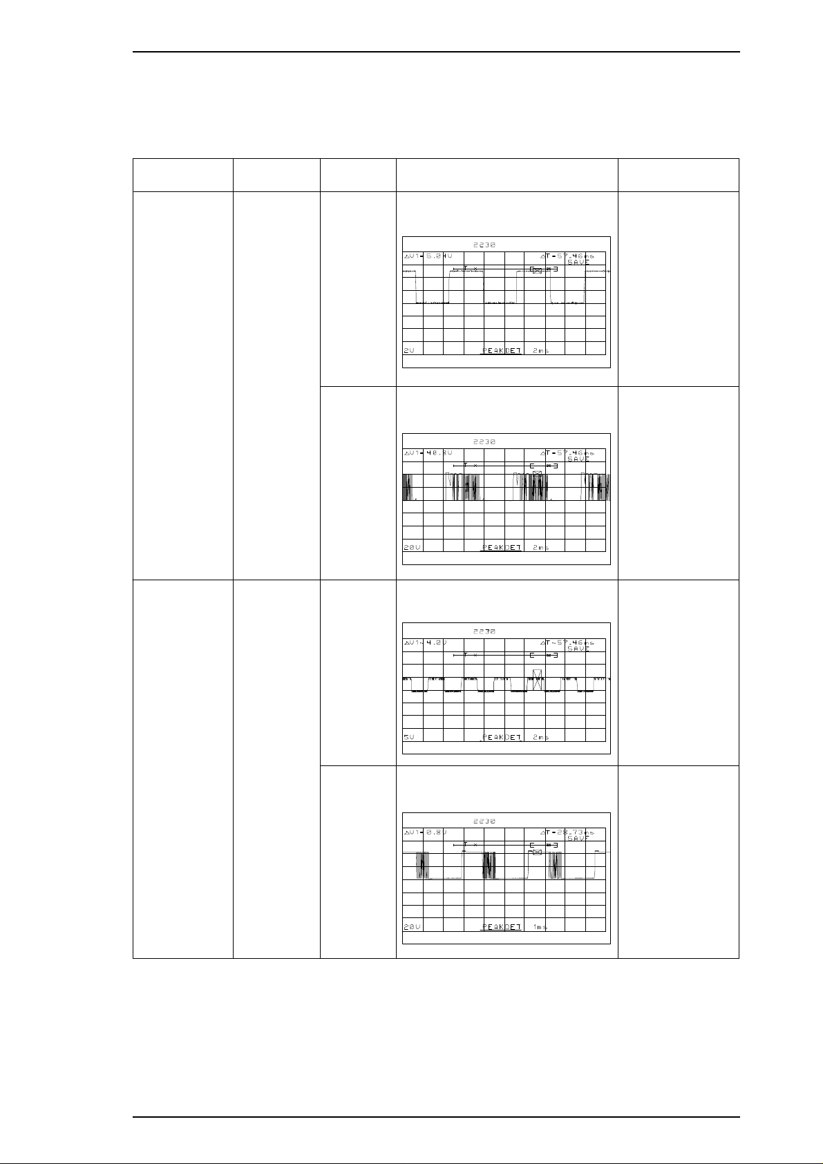
Stylus Color IIs / Stylus 820 Troubleshooting
Table 5-4. Repair of C160 MAIN(Cont.)
SolutionPhenomenon Condition Cause Checkpoints
Carriage does
not operate
normally.
PF motor does
not operate
normally.
Drive pulse
does not
output.
Drive pulse
does not
output.
CPU is
defective.
IC12 is
defective.
CPU is
defective.
Does the wave-form correct?
(Check pin either at 9 and 10.)
Does the wave-form correct?
(Check pin at 17,20 and 14,23.)
Does the wave-form correct?
(Check pin either at 3 and 4.)
Replace CPU.
Correct : replace
motor.
Incorrect : repalce
IC12.
Replace CPU.
IC16 is
defective.
Does the wave-form correct?
(Check pin at 17,20 and 14,23.)
Correct : replace
motor.
Incorrect : repalce
IC12.
Rev. A 5-5
Page 91

Troubleshooting Stylus Color IIs / Stylus 820
5.4 Repair of PRINTER MECHANISM (M-4C10)
Any problems related to the printer mechanism should be repaired according to the troubleshooting
procedures in Table 5-7.
Table 5-5. Repair of the Printer Mechanism
Symptom Condition Cause Checkpoint Solution
The pump
mechanism
does not
operate.
The carriage
motor does
not rotate.
The PF motor
fails to rotate at
power on.
Used ink does
not go through
the used ink
tube during the
cleaning
operation.
The carriage
motor fails to
rotate at power
on.
PF motor is
defective.
Carriage flag is
defective.
The tube is not
properly
connected to the
cap.
The ink tube is
damaged.
The cap is
defective.
The pump is
defective.
The printhead is
defective.
PG value is
incoorect.
CRHP sensor is
defective.
The carriage
motor is defective.
Measure the coil
resistance of the CR motor.
21 Ω±1Ω
Check the flag on the back
of the carriage unit.
Check that the tube is
properly connected to the
cap.
Check the ink tube visually.
Check for any defective
part.
Replace the pump to see if
this causes the ink to be
absorbed normally.
Replace the printhead to
see if this causes the ink
to be absorbed normally.
Check the PG value.
(1.18 mm ± 1/100)
Check voltage reaction at
pin 1 on CN8.
Measure the coil
resistance of the CR motor.
22 Ω±7%
Remove any
foreign
substance.
Replace the
carriage unit.
Insert the tube
properly.
Replace the
tube.
Replace the
head cap.
Replace the
pump unit.
Replace the
printhead.
Remove any
foreign
substances.
Replace
CRHP.
Replace the
carriage
motor.
The pulley is
The carriage
does not
operate
normally at
power on
(after the
carriage has
been
manually
centered
prior to
power on).
5-6 Rev. A
The carriage
motor rotates,
but the carriage
does not move.
The carriage
moves slightly
and then stops.
defective.
The timing belt is
defective.
Carriage
movement is not
smooth.
Check for broken or worn
pulley.
Check that the timing belt
is properly inserted into
the bottom of the carriage.
Check the timing belt for
any damage.
Check whether the
carriage moves smoothly
when moved manually.
Check tension of the
timing belt.
Replace the
driven pulley.
Reinsert the
timing belt.
Replace the
timing belt.
Clean and
lubricate the
carriage.
Adjust tension
of the timing
belt.
Page 92

Stylus Color IIs / Stylus 820 Troubleshooting
5.5 Dot missing Trouble shooting Guide
This section describes how to recover the clogged nozzle when you receive the dot-missing printer.
Since the print head of this printer is the new system, it is very difficut to eliminate the invaded air bubble
from the print head unit or the ink cartridge so that, never use again if you remove once a ink cartridge from
the main unit.
Also, we prepair the special ink cartridge exclusive for your service side. Please refer to the under table for
low price ink cartridge.
Table 5-6. Ink Cartridge exclusive for the service side
Ink Cartridge Code
Black ink cartridge 1023206
Color Ink cartridge 1023207
Note: Please read throughly under the cautions before you start to repair.
WARNING 1
Do not re-use a removed ink cartridge when you return the printer to your user.
WARNING 2
Since the ink end sensor is counted by the firmwear counter, it is a possibility that the life of
brand-new ink cartridge can not be guranteed if you reuse the removed ink cartridge so that,
perform the EEPROM reset after replace the ink cartridge.
WARNING 3
There are two reset methods for clear the EEPROM . Select a proper method referring the
Section 4.1.5.
Rev. A 5-7
Page 93

Troubleshooting Stylus Color IIs / Stylus 820
5.5.1 How to recover the dot-missing with the brand-new ink cartridge
The under flow-chart shows the way of the recovering a clogged nozzle with the ink cartridge. The section
that is indicated the out of each items shows the additional explanation when you want to help a detail
contents.
Start
Refer to Section 5.5.1.1.
Perforn the 360 DPI printing.
A
Does the
printing normal?
Refer to Section 5.5.1.3.
Refer to Section 5.5.1.1.
Perform the CL operation
for 2 or 3 times.
Perforn the 360 DPI printing.
Printing is recovered?
Replace to new ink cartridge.
Printing is recovered?
Refer to Section 5.5.1.2.
Yes
No
Refer to Section 4.1.3.
Refer to Section 4.1.2.
Yes
No
No
Yes
A
Printing is recovered?
Refer to Section 5.5.1.4.
Does the
head angle
correct?
Perform the head angle
adjustment.
Perform the Bi-D adjustment.
A
Refer to Section 5.5.1.5.
Perform the initila ink charge
with the program.
Perform the initila ink charge
with the program.
No
Refer to Section 4.1.2.
Perform the Bi-D adjustment.
Perform the EEPROM reset &
replace a waste ink drain pad.
Replace to new ink cartridge.
Refer to Section 5.5.1.5.
Perform the initila ink charge
with the program.
Refer to Section 4.1.5.
END
Perforn the 360 DPI printing.
Refer to Section 5.5.1.1.
Perforn the 360 DPI printing.
Refer to Section 5.5.1.1.
Perforn the 360 DPI printing.
Refer to Section 5.5.1.4.
Does the head
angle correct?
Yes
A
Printing is recovered?
Yes
Refer to Section 4.1.5.
No
Perform the EEPROM reset &
replace a waste ink drain pad.
Refer to Section 5.5.1.6.
Replace to new print head.
Replace to new ink cartridge.
A
Refer to Section 4.1.3.
Yes
Perform the head angle
adjustment.
Refer to Section 4.1.2.
Perform the Bi-D adjustment.
END
Figure 5-2. Main Flow-Chart for Recover a Dot-missing
5-8 Rev. A
Page 94
Stylus Color IIs / Stylus 820 Troubleshooting
5.5.1.1 How to Perform the 360-DPI Printing
It is possible to confirm the any problems with the 360-DPI check pattern printing. Also, if you receive the
white banding problem, you can confirm the wrong condition quickly. Please perform the proper repir
referring under explanations.
[Step 1] Connect the host computer to the printer with the printer cable.
[Step 2] Insert the paper to the hopper and load a paper.
[Step 3] Run the GWBASIC on the host computer, then execute the program. The file name is
“HUDSON.BAS”.
[Step 4] The initila menu will be appeared on the display.
STYLUS / MJ Program : H90E00E
***** Model *****
1. STYLUS COLOR IIs
2. STYLUS 820
3. MJ-500C
7. END
Select Menu ? “_”
[Step 5] Select option 1 or 2 depending on the market. (Never select option 3.)
[Step 6] The next menu will be appeared on the display.
STYLUS / MJ Program : H90E00E
***** Customer *****
1. EAI, EAI (Latin America), EAL, ESP, ETT
2. EUL, EDG, EIS, EIB,EUL(North Europe), EUL (Middle EAST), EHK
3. [ EDG(NLSP) ]
4. Russia
Select Menu ? “_”
[Step 7] Select your country umber. you can register the CG table and the panel default set at this time.
Then the adjustment menu will be appeared on the display.
STYLUS Program : H90E00E
Model : STYLUS COLORIIs(STYLUS 820)
Customer : EAI, EAI Latin, ——-, etc.
1. Ink discharge (BLACK)
2. Ink discharge (COLOR)
3. Head Angular Adjustment
4. Bi-D Adjustment (Bi-D center -15)
5. A4 check pattern (BLACK)
6. A4 check pattern (COLOR)
7. Envelop
8. Index card/Post card
0. Change Customer & Model / END
13. BLACK Ink Counter Reset
14. COLOR Ink Counter Reset
Select Menu ? “_”
Rev. A 5-9
Page 95
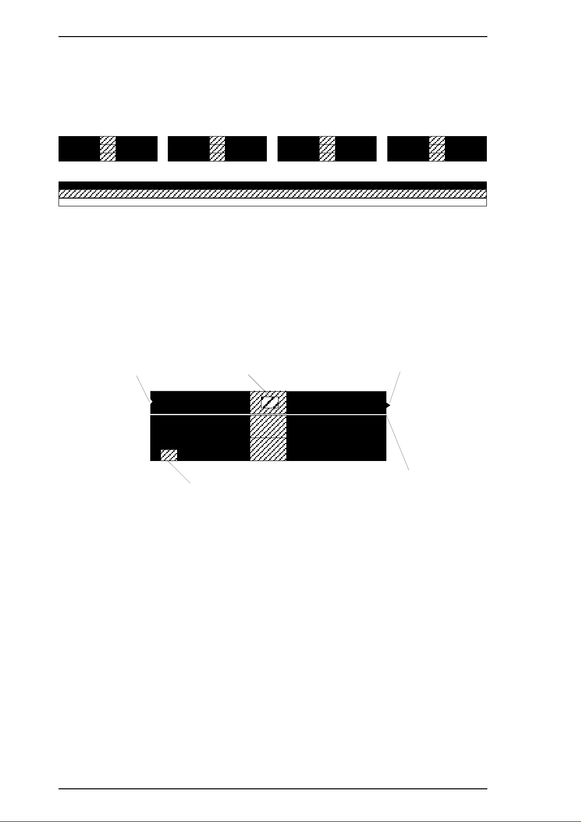
Troubleshooting Stylus Color IIs / Stylus 820
[Step 8] Select the option 5 or option 6 depending on your printer head. Then the display indicates the “MC
No. ? ”_"
[Step 9] Press the return key. Then the printer automatically prints a check pattern.
First, the TOF line is printed, then the 360-DPI full duty pattern will be appeared.
2.BETA(With the black head)
3.BETA(With the color head)
Figure 5-3. 360-DPI Check Pattern
Note: Select the correct value on the display because both pattern and color are different depending on
the head units.
[Step 10] We can imagin the miss-alignment or the dot-missing if the above pattern has a white banding or
the smear part, so that advance to next step (Section 5.5.1.2) on the main flow-chart.
5.5.1.2 Standard of “ Does the printing normal?”
If the 360-DPI printing pattern has a under problem, advance to next step (Section 5.5.1.3)
There is a hollow place.
Smear part
Smear part
There is a projection part.
White banding
Figure 5-4. Standard of Dot-missing
5-10 Rev. A
Page 96

Stylus Color IIs / Stylus 820 Troubleshooting
5.5.1.3 Performing the CL operation for 2 ~ 3 times
This section describes the cleaning operation if you find a print missing on the 360-DPI check pattern. You
need a confirmation either the CL opeartion is correctly performed or not in this function..
[Step 1] Remove the upper case. (See the Section 3.2.1.)
[Step 2] Perform the CL operation. (Under the puase state, pressing the Pause button while you pressing
the Alt button.)
[Step 3] Attention the waste ink drain tube either the ink is correctly supplied or not. If an ink is not
correctly supplied, check the under items before you advance to next step on the main flow-chart.
Note:
Cap rubber surface
Bent part
Sponge
Figure 5-5. The Bent part on the Cap rubber
If you can not find a any problems about the pump unit system or the above contents,
there is a possibility that an ink inside the ink cartridge has already emptied in spite of
any counter values, so that it is necessary to replace to brand-new ink cartridge when you
can not find any problems.
Also, if user perform the removing or installing with the same ink cartridge, it will not
recover the dot-missing every time you perform the CL operation, because the
constructure of the print head is very complexity as compair to previous head system.
Therefore, replace to brand-new ink cartridge at this time.
Rev. A 5-11
Page 97

Troubleshooting Stylus Color IIs / Stylus 820
5.5.1.4 Does the Head angle correct?
This section describes either the head angle condition is correct or not. Refer to Section 4.1.3 in the acrual
adjustment.
[Step 1] Perform the head angle adjustment. (Refer to Section 4.1.3.)
Note: If the head angle condition is wrong, white or color banding problem will be appeared on the
graphic pattern.
5.5.1.5 Perform the initila ink charge with the program
A clogged nozzle will be recovered with a large quantity of an ink by performing the initial ink charge
operation.
[Step 1] Perform the Step 1 to Step 7 in the Section 5.5.1.1.
[Step 2] Press either the option 1 or option 2 depending on the print heads, then the next message (“Now
Ink discharge”) appears on the display.
Note 1: Select a correct option with referring the current print head unit.
Note 2: There is a EEPROM all reset routine in the end of this option, so that, it is necessary to replace the
waste ink drain pad if you perform this initial ink charge operation.
5.5.1.6 Replace to new ink cartridge
It is necessary to replace the print head unit if you can not recover a alogged nozzle by performing the initial
ink charge, CL operation and replacing the new ink cartridge.
If you replace to new ink cartridge, do not re-use a removed ink cartridge again.
5-12 Rev. A
Page 98

Chapter 6 Maintenance
Table of Contents
6.1 PREVENTIVE MAINTENANCE 6-1
6.1.1 PrintheadCleaning..........................................6-1
6.1.2 WasteInkDrainTankReplacement............................6-1
6.2 LUBRICATION AND ADHESIVE 6-2
LIST OF FIGURES
Figure6-1.LubricationPointsandAdhesivePoints ...................6-3
LIST OF TABLES
Table6-1.RecommendedLubricants................................6-3
Table6-2.LubricationPoints ......................................6-4
Table6-3.AdhesivePoints........................................6-4
Rev. A 6-i
Page 99

Stylus Color IIs / Stylus 820 Maintenance
6.1 PREVENTIVE MAINTENANCE
This printer must be lubricated only O9 when you need a lubrication for carriage guide shaft. If you lubricate
with another oil, it could permanently damage the print head unit..
Although this printer requires no specific maintenance on a regular basis, recommends that you clean the
following thoroughly whenever you get a chance.:
❏ Outer case
Use a soft, clean cloth, dampened with mild detergent, if necessary.
❏ Auto sheet feeder
If the inside of the auto sheet feeder is dirty (dusty), carefully brush away all dust and dirt using a soft
brush. If the pickup roller of the sheet feeder is dirty, clean its surface with a soft, clean cloth.
❏ Inside the printer
If you notice any dust or dirt that has accumulated inside the printer when you open the outer case for
repair, remove all dust and dirt using a small vacuum cleaner designed for such purposes.
Warning
❏ Use only O9 oil when lubricationg the carriage guide shaft. If you lubricate with another oil, it
could permanently damage the print head unit.
❏ Never use paint thinner, trichloroethyylene, or ketone-based solvents for cleaning. These
chemicals can damage the components the printer.
❏ Do not use a hard or abrasive brush for cleaning.
❏ Be careful not to damage the components of the printer when using a vacuum cleaner.
6.1.1 Printhead Cleaning
If print quality deteriorates, clean the printhead using the built-in printhead cleaning function. The printer also
has an automatic printhead cleaning cycle to ensure proper nozzle operation for ink ejection and to preserve
the printhead in the best condition. Because of the automatic cleaning cycle, you need to perform this manual
printhead cleaning operation only if print quality declines. Performing the cleaning more often wastes ink.
1. Turn the printer on and press the Pause button to pause the printer. Make sure that the PAUSE LED is
on.
2. Hold down the Alt button and press the Load/Eject button to clean the printhead.
When the printer accepts the panel switch operation, the PAUSE LED flashes during the cleaning cycle.
When the cleaning completes, the PAUSE LED stops flashing and returns to PAUSE mode.
6.1.2 Waste Ink Drain Tank Replacement
The printer counts the total amount of ink drained to the waste ink tank, and this information is stored in the
EEPROM on the main board (Protect counter A) for ink system operation management. If the value of this
counter reaches a predetermined value, the printer displays an error (“Waste ink tank overflow,” see Chapter
1, Section 1.4.1, Error Conditions, Table 1-14). When this error is displayed, replace the waste ink drain pad
and reset the protect counter.
1. Open the upper case and remove the waste ink drain pad from the compartment in the lower case. Insert
fresh ink pad and reassemble the printer.
2. Turn the printer while holding down the Alt and Pause buttons.
3. Then holding dawn the Load/Eject for 10-seconds.
4. If printer accepts the reset mode, the Pause and Economy LED starts to brinks. And if printer can not
accept, return to step 1.
5. Under this condition, press the Alt button, then initialize operation will be automatically perforemed.
(For detail, refer to Section 4.1.5.)
Rev. A 6-1
Page 100
Maintenance Stylus Color IIs / Stylus 820
6.1.3 Lubrication and Adhesives
The printer must be lubricated properly when it is disassembled for component replacement, or if mechanical
noise exceeds a certain level. EPSON recommends only the lubricants listed in table below for this printer.
They have been tested extensively and found to comply with the requirements of this printer mechanism.
Figure 6-1 shows the lubrication points.
Warning
❏Use only O9 oil when lubricationg the carriage guide shaft. If you lubricate with another oil, it
could permanently damage the print head unit.
Table 6-1. Recommended Lubricants
Type Name Quantity Part No. Availability
Oil
Grease
Adhesive NEJI LOCK #2 (G) 1000 g B730200200 E
Note: E = EPSON Exclusive product (not commercially available)
O-9 TBD TBD E
O-5 40 cc 1010513 E
G-20 40 gm B700000001 E
G-36 40 gm B703600001 E
Table 6-2. Lubrication Points
Ref. No. Lubrication Point Name/Quantity
(1) Oil pad on the carriage G-9 (1-3 mg)
(2) Pick up roller hole on the Pump unit G-36 (1-3 mg)
(3) Bothsidesoftheplatenunit G-36(1-3mg)
(4) Pump transmission gear (Black color) G-36 (1-3 mg)
(5) Clutch mechanism (Between PF and pump) G-36 (1-3 mg)
(6) Left shaft on the paper feed roller unit G-36 (1-3 mg)
(7) E-ring on the paper feed roller unit (Right side) G-36 (1-3 mg)
(8) Pump transmission gear surface G-36 (1-3 mg)
(9) Rail surface on the paper select lever G-36 (1-3 mg)
Table 6-2. Adhesive Points
Ref. No. Adhesive Point Name/Quantity
(1) A part of timing belt securing on the carraige unit #2 (G) (1-3 mg)
CAUTION
❏Do not apply too much lubricant, as it may stain the printer or cause a malfunction of
the mechanism.
6-2 Rev. A
 Loading...