

Page 1
SERVICE MANUAL
Color Inkjet Printer
EPSON STYLUSCOLOR680/777/777i
®
SEIJ00010
Page 2

Notice
o
All rights reserved. No part of this manual may be reproduced, stored in a retrieval system, or transmitted in any form or by any means electronic,
mechanical, photocopying, or otherwise, without the prior written permission of SEIKO EPSON CORPORATION.
o
All effort have been made to ensure the accuracy of the contents of this manual. However, should any errors be detected, SEIKO EPSON would
greatly appreciate being informed of them.
o
The contentsof this manual are subject to change without notice.
o
All effort have been made to ensure the accuracy of the contents of this manual. However, should any errors be detected, SEIKO EPSON would
greatly appreciate being informed of them.
o
The above not withstanding SEIKO EPSON CORPORATION can assume no responsibility for any errors in this manual or the consequences
thereof.
EPSON is a registered trademark of SEIKO EPSON CORPORATION.
General Notice: Other product names used herein are for identification purpose only and may be trademarks or registered trademarks of their
respective owners. EPSON disclaims any and all rights in those marks.
Copyright © 2000 SEIKO EPSON CORPORATION. Printed in Japan.
Page 3

PRECAUTIONS
Precautionary notations throughout the text are categorized relative to 1)Personal injury and 2) damage to equipment.
DANGER Signals a precaution which, if ignored, could result in serious or fatal personal injury. Great caution should be exercised in performing
procedures preceded by DANGER Headings.
WARNING Signals a precaution which, if ignored, could result in damage to equipment.
The precautionary measures itemized below should always be observed when performing repair/maintenance procedures.
DANGER
1. ALWAYS DISC ONNECT THE PRODUCT FROM THE POWER SOURCE AND PERIPHERAL DEVICES PERFORMING ANY
MAINTENANCE OR RE PAIR PROCEDURES.
2. NO WORK SHOULD BE PERFORMED ON THE UNIT BY PERSONS UNFAMILIAR WITH BASIC SAFETY MEASURES AS DICTATED
FOR A LL ELECTRONICS TECHNICIANS IN THEIR LINE OF WORK.
3. WHEN P ERFORMING TESTING AS DICTATED WITHIN THIS MANUAL, DO NOT CONNECT THE UNIT TO A POWE R SOURCE UNTIL
INSTRUCTED TO DO SO. WHEN THE POWER SUPPLY CABLE MUST BE CONNECTED, USE EXTREME CAUTION IN WORKING ON
POWER S UPPLY AND OTHER ELECTRONIC COMPONENTS.
WARNING
1. REPAIRS ON EPSON PRODUCT SHOULD BE PERFORMED ONLY BY AN EPSON CERTIFIED REPAIR TECHNICIAN.
2. MAKE CE RTAIN THAT THE SOURCE VOLTAGES IS THE SAME AS THE RATED VOLTAGE, LISTED ON THE SER IAL NUMBER/
RATING PLATE. IF THE EPSON PRODUCT HAS A PRIMARY AC RATING DIFFERENT FROM AVAILABLE POWER S OURC E, DO NOT
CONNECT IT TO THE POWER SOURCE.
3. ALWAYS V ERIFY THAT THE EPSON PRODUCT HAS BEEN DISCONNECTED FROM THE POWER SOURCE BEFORE REMOVING OR
REPLACING PRINTED CIRCUIT BOARDS AND/OR INDIVIDUAL CHIPS.
4. IN ORDER TO PROTECT SENSITIVE MICROPROCESSORS AND CIRCUITRY, USE STATIC DISCHARGE EQUIPMENT, SUCH A S
Page 4

About This Manual
This manual describes basic f unctions, theory of electrical and mechanical operations, maintenance and repair procedures of EPSO N Stylus Color 680/777/777i.
The instructions and procedures included herein are intended for the experienced repair technicians, and attention should be given to the precautions on the
preceding page.
Contents
This manual consists of six chapters and one Appendix.
CHAPTER 1.PRODUCT DESCRIPTIONS
Provides a general overview and specifications of the product.
CHAPTER 2.OPERATING PRINCIPLES
Describes the theory of electrical and mechanical operations of the product.
CHAPTER 3.TROUBLESHOOTING
Provides the step-by-step procedures for the troubleshooting.
CHAPTER 4.DISASSEMBLY AND ASSEMBLY
Describes the step-by-step procedures for dissaembling and assembling the product.
CHAPTER 5.ADJUSTMENTS
Provides Epson-approved methods for adjustment.
CHAPTER 6.MAINTENANCE
Provides preventive maintenance procedures and the lists of Epson-approved lubricants and a dhesives
required for servicing the product.
APPENDIXProvides the following additional information for reference:
• Connector pin assignments
• Electric circuit boards c omponents layout
• Exploded diagram
• Electricalcircuitboardsschematics
Page 5

Symbols Used in This Manual
Various symbols are used throughout this manual either to provide additional information on a specific topic or to warn of possible danger present during a
procedure or an a ction. B e aware of all symbols when they are used, and always read W ARNI NG, CAUTION or NOTE messages.
W A R N I N G
C A U T I O N
C H E C K
P O I N T
Indicates an operating or maintenance procedure, practice or condition that, if not strictly observed, could result in injury or loss of life.
Indicates an operating or maintenance procedure, practice, or condition that, if not strictly observed, could re sult in damage to, or destruction of,
equipment.
May indicate an operating or maintenance procedure, practice or condition that is necessary to accomplish a task efficiently. It may also provide
additional information that is related to a specific subject, or comment on the results achieved through a previous action.
Page 6
Revision Status
Revision Issued Date Description
A August 10, 2000 First Release
Revision:
n
B August 31, 2000
Added disassembly and reassembly caution to 4.2.1 Housing Removal
n
Changed the resolution of bit map images when producing PDF files for clearer
reading.
Page 7

Chapter 1 PRODUCT DESCRIPTION
1.1 FEATURES ........................................................................................ 10
1.2 SPECIFICATIONS..............................................................................11
1.2.1 Physical Specification............................................................... 11
1.2.2 Printing Specification................................................................ 11
1.2.3 Paper Feeding.......................................................................... 12
1.2.4 Input Data Buffer...................................................................... 12
1.2.5 Electric Specification................................................................ 12
1.2.6 Environmental Condition.......................................................... 13
1.2.7 Reliability.................................................................................. 13
1.2.8 Safety Approvals...................................................................... 13
1.2.9 Acoustic Noise.......................................................................... 13
1.2.10 CE Marking............................................................................. 13
1.3 INTERFACE....................................................................................... 14
1.3.1 Parallel Interface (Forward Channel) ....................................... 14
1.3.2 Parallel Interface (Reserve Channel)....................................... 17
1.3.3 USB Interface........................................................................... 18
1.3.4 Prevention of Data Transfer Time-out...................................... 19
1.3.5 Interface Selection.................................................................... 19
1.3.6 IEEE1284.4 Protocol ................................................................19
1.4 OPERATOR CONTROLS .................................................................. 20
1.4.1 Operating Switch...................................................................... 20
1.4.2 Control P anel............................................................................ 20
1.4.3 Panel Functions........................................................................ 21
1.4.4 Printer Condition and Panel Status.......................................... 22
1.4.5 Printer Initialization................................................................... 22
1.4.6 Errors........................................................................................ 23
1.5 PAPER ............................................................................................... 24
1.5.1 Paper Handling......................................................................... 24
1.5.2 Paper Specification.................................................................. 24
1.5.3 Printing Area............................................................................. 26
1.6 INK CARTRIDGE............................................................................... 28
1.6.1 Black Ink Cartridge................................................................... 28
1.6.2 Color Ink Cartridge................................................................... 28
2.1.1 Printer Mechanism ................................................................... 30
2.1.2 Printhead.................................................................................. 31
2.1.3 Carriage Mechanism ................................................................ 33
2.1.4 Paper Feeding Mechanism ...................................................... 34
2.1.5 Paper Loading Mechanism (ASF Unit)..................................... 35
2.1.6 Ink System Mechanism............................................................ 38
2.2 Electrical CircuitO perating Principles................................................ 40
2.2.1 C383 PSB/PS E board.............................................................. 40
2.2.2 C383 MAIN Board.................................................................... 43
Chapter 3 Troubleshooting
3.1 Overview ............................................................................................ 50
3.2 Troubleshooting with LED Error Indications....................................... 51
Chapter 4 Disassembly and Assembly
4.1 Overview ............................................................................................ 62
4.1.1 Precautions .............................................................................. 62
4.1.2 Tools ........................................................................................ 63
4.1.3 Work Completion Check .......................................................... 64
4.2 Disassembly....................................................................................... 65
4.2.1 Housing removal...................................................................... 66
4.2.2 OperationPanel removal ......................................................... 67
4.2.3 Printhead removal .................................................................... 68
4.2.4 CR motor removal.................................................................... 71
4.2.5 Waste drain ink pad unit removal ............................................. 73
4.2.6 Circuit board removal............................................................... 75
4.2.7 LD Roller removal .................................................................... 79
4.2.8 HP/PE Sensor removal............................................................ 83
4.2.9 Ink system unit removal (Cap & Pump unit )............................ 85
4.2.10 Paper Eject Roller removal .................................................... 87
4.2.11 PF motor removal................................................................... 89
4.2.12 CR unit removal ..................................................................... 91
4.2.13 Paper feed roller removal....................................................... 94
4.2.14 DisassemblingASF frame unit............................................... 97
Chapter 2 Operating Principles
2.1 Overview............................................................................................. 30
Chapter 5 Adjustment
5.1 Overview .......................................................................................... 101
Page 8

5.1.1 Required Adjustment.............................................................. 101
5.1.2 Adjustment Program feature.................................................. 102
5.1.3 Adjustment Program Installation Procedure........................... 103
5.1.4 Adjustment Program Initial Setting menu...............................103
5.1.5 Head ID Input......................................................................... 103
5.1.6 Bi-D Adjustment .....................................................................105
5.1.7 USB ID input...........................................................................107
5.1.8 Head Cleaning Operation . ...................................................... 109
5.1.9 Initial Ink Charge Operation.................................................... 110
5.1.10 Refurbishmentfor DOA........................................................ 111
5.1.11 Protection Counter Check/Reset.......................................... 112
5.1.12 Check pattern printing.......................................................... 114
5.1.13 EEPROM check function...................................................... 115
5.1.14 CSIC Information.................................................................. 116
Chapter 6 Maintenance
6.1 Overview...........................................................................................1 18
6.1.1 Cleaning................................................................................. 118
6.1.2 Service Maintenance.............................................................. 119
6.1.3 Lubrication..............................................................................1 19
Chapter 7 Appendix
7.1 Connector Sum mary......................................................................... 124
7.1.1 Major Component Unit ........................................................... 124
7.1.2 EEPROM Address Map.......................................................... 127
7.2 C omponent L ayout........................................................................... 1 31
7.3 Expl oded Diagram.. .......................................................................... 133
7.4 Parts List........................................................................................... 138
7.5 Electrical Circuits.............................................................................. 141
Page 9

PRODUCTDESCRIPTION
CHAPTER
1
Page 10
EPSON Stylus COLOR 680/777/777i Revision B
F
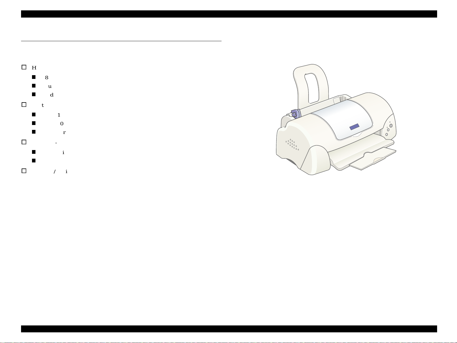
1.1 FEATURES
The major features of EPSON color inkjet printers EPSON Stylus COLOR 680/777/
777i are:
o
High Color Print Qua lity
n
2880 (H) X 720 (V) dpi printing
n
Four Color Printing (YMCK)
n
Traditional and New Microweave
o
Built-inAutoSheetFeeder
n
Holds 100 cut-sheets(64g/m2)
n
Holds 10 envelopes
n
Holds 1 transparency films
o
Two Built-in Interfaces
n
Bi-directional parallel I/F (IEEE-1284level 1 device)
n
USB
o
Windows/Macintosh exclusive
Figure 1-1. External View
PRODUCT DESCRIPTION
EATURES 10
Page 11
EPSON Stylus COLOR 680/777/777i Revision B
S
1.2 SPECIFICATIONS
This section covers specifications of the printers.
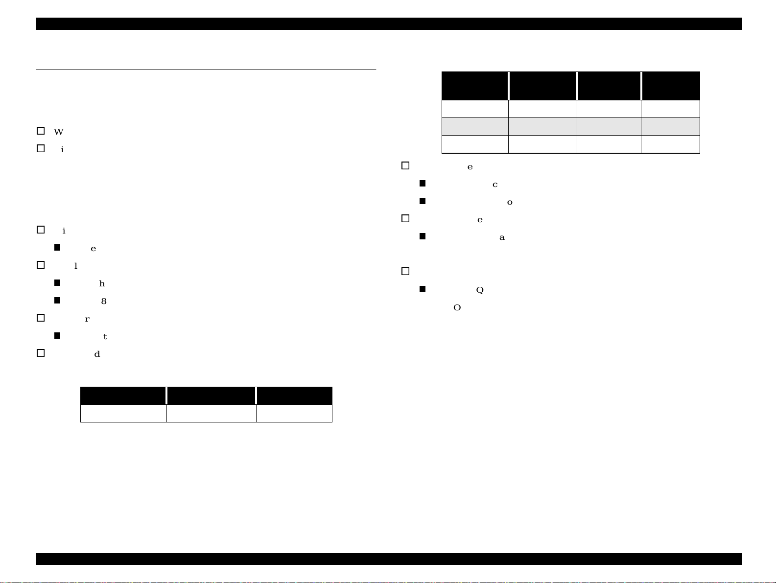
1.2.1 Physical Specification
o
Weight: 4.1kg (without ink cartridges)
o
Dimension:
Storage: 450 mm (W) x 246 mm (D) x 182 mm (H)
Printing: 450 mm (W) x 547 mm (D) x 279 mm (H)
1.2.2 Printing Specification
o
Print Method
n
On demand ink jet
o
Nozzle Configuration
n
Monochrome 144 noz zles (48 x 3 staggered)
n
Color 48 nozzles x 3 (Cyan, Magenta, Yellow)
o
Print Direction
n
Bi-direction with logic seeking
o
Control Code
n
ESC/P Raster command
n
EPSON Remote command
o
Character Tables
n
Two international character sets:
- PC 437 (US, Standard Europe)
o
Typeface
n
Bit map LQ font:
EPSON Courier 10 CPI
Table1-2. RasterGraphicsMode
Horizontal
Resolution
360 dpi 8.26 inches 2976 23.8 IPS
720 dpi 8.26 inches 5952 20 IPS
1440 dpi 8.26 inches 11904 20 IPS
Printable Area AvailableDot CR Speed
o
Print Speed & Printable Columns
Table 1-1. Character Mode
CharacterPitch PrintableColumn LQ Speed
10 CPI (Pica) 80 238 CPS*
*This value is the speed of normal-dot printing.
PRODUCT DESCRIPTION
PECIFICATIONS 11
Page 12

EPSON Stylus COLOR 680/777/777i Revision B
S
1.2.3 Paper Feeding
o
Feed Method
n
Friction feed with ASF
o
Paper Path
n
Cut-sheet ASF (Top entry, Front out)
o
Feed Speed
n
2.36 inch/sec (Normal, Continuous feed)
n
4.5 inch/sec (Fast, Continues feed)
1.2.4 Input Data Buffer
n
32KB
1.2.5 Electric Specification
[120V Version]
Rated Voltage: AC120V
Input Voltage Range: AC99∼132V
Rated Frequency Range: 50∼ 60Hz
Input Frequency Ra nge: 49.5∼ 60.5Hz
Rated Current: 0.4A
Power Consumption: Approx. 17W (ISO10561 Letter Pattern)
Approx. 2.5W in standby m ode
Energy Star compliant
Insulation Resistance: 100M ohms min.
(between AC line and chassis, DC 500V)
Dielectric Strength: AC 1000V rms. 1 minutes or
AC 1200V rms. 1 second
(betweenAC line and chassis)
[220 ∼ 240V Version]
Rated Voltage: AC220V∼240V
Input Voltage Range: AC198∼264V
Rated Frequency R ange: 50∼60Hz
Input Frequency Range: 49.5∼60.5Hz
Rated Current: 0. 2 A (for Stylus Color 860)
0.2 A (for Stylus Color 1160)
Power Consumption: Approx. 17W (ISO10561 Letter Pattern)
Approx. 2.5W in standby mode
Energy Star compliant
Insulation Resistance: 100M ohms min.
(between AC line and chassis, DC 500V)
Dielectric Strength: AC 1500V rms. 1 minute
(between AC line and chassis)
PRODUCT DESCRIPTION
PECIFICATIONS 12
Page 13
EPSON Stylus COLOR 680/777/777i Revision B
S
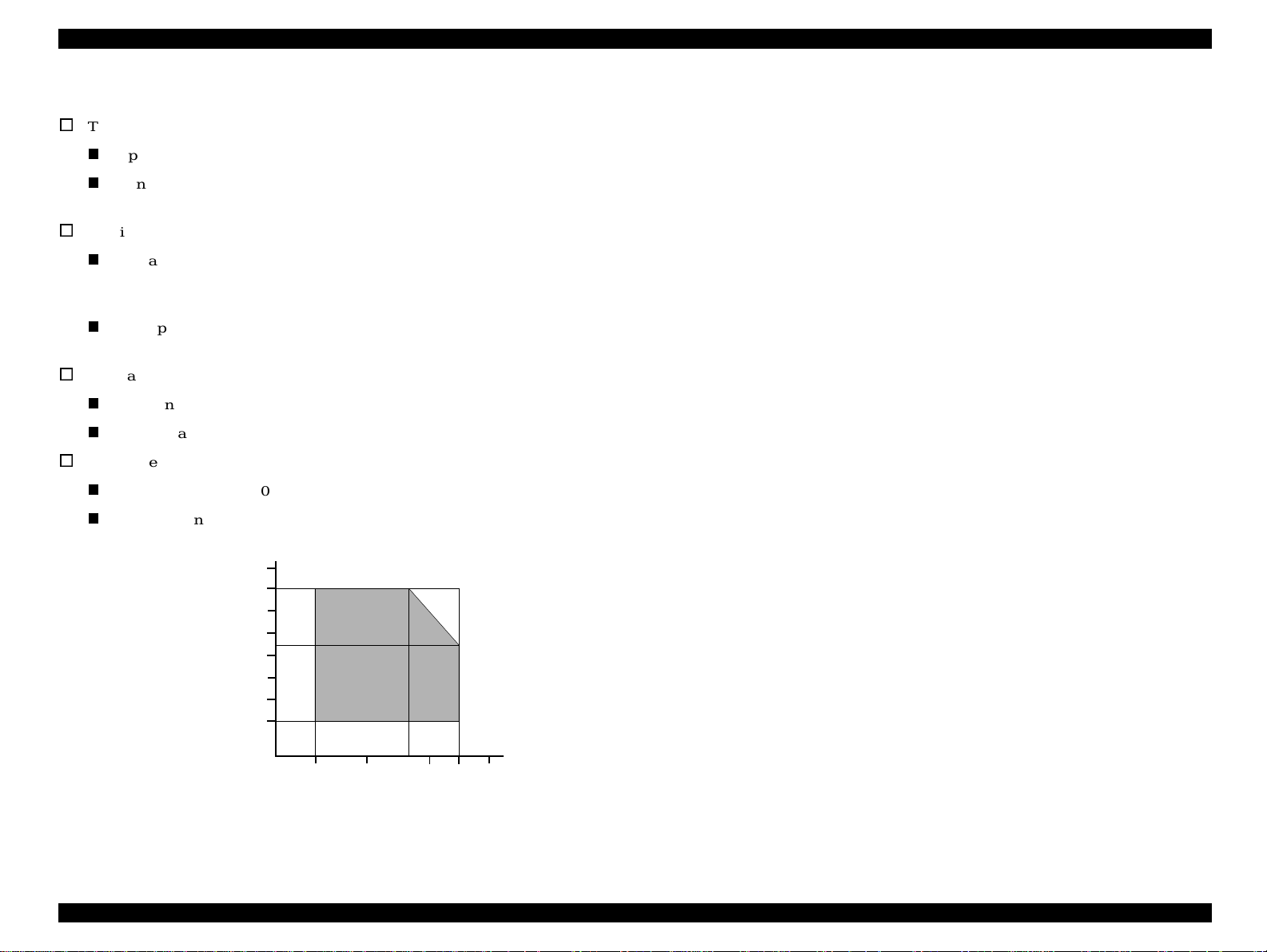
1.2.6 Environmental Condition
o
Temperature
n
Operating: 10 to 35°C (see the figure below for condition)
n
Non-operating: -20 to 60°C (with shipment container)
1monthat40°C and 120 hours at 60°C
o
Humidity
n
Operating: 20 to 80% RH
(without c ondensation / see the figure below for
condition)
n
Non-operating: 5 to 85% RH
(without c ondensation / with shipment container)
o
Resistance to Shock
n
Operating: 1G, within 1 ms
n
Non-operating: 2G, within 2 ms (with shipment container)
o
Resistance to Vibration
n
Operating: 0.15G
n
Non-operating: 0.50G (with s hipment container)
90
80
70
60
Humidity (%)
50
40
30
20
10
Temperature (°C)
1.2.7 Reliability
Total Print Volume: 50,000 pages (A4, Letter)
or 5 years although less than 50.000 pages printing
Print Head Life: 3 billion dots/nozzle
1.2.8 Safety Approvals
[120V Version]
Safety Standards: UL1950
CSA22.2 No.950
EMI: FCC part 15 subpart B Class B
CSA C108.8 Class B
[220∼240V Version]
Safety Standards: EN60950 (VDE)
EMI: EN55022 (CISPR Pub.22) Class B
AS/NZS 3548 Class B
1.2.9 Acoustic Noise
Level: Approx. 47dB(A) (According to ISO 7779)
-Used media : Plain Paper
- Print Quality: Fine
1.2.10 CE Marking
[220∼240V Version]
Low Voltage Directive 73/23/EEC: EN60950
EMC Directive 89/336/EEC: EN55022 Class B
EN61000-3-2
EN61000-3-3
EN50082-1
27
20
30
35 40
IEC801-2
IEC801-3
IEC801-4
Figure 1-2. Temperature/Humidity Range
PRODUCT DESCRIPTION
PECIFICATIONS 13
Page 14
EPSON Stylus COLOR 680/777/777i Revision B
1.3 INTERFACE
The EPSON Stylus COLOR 680/777/777i provide USB and parallel interface as
standard.
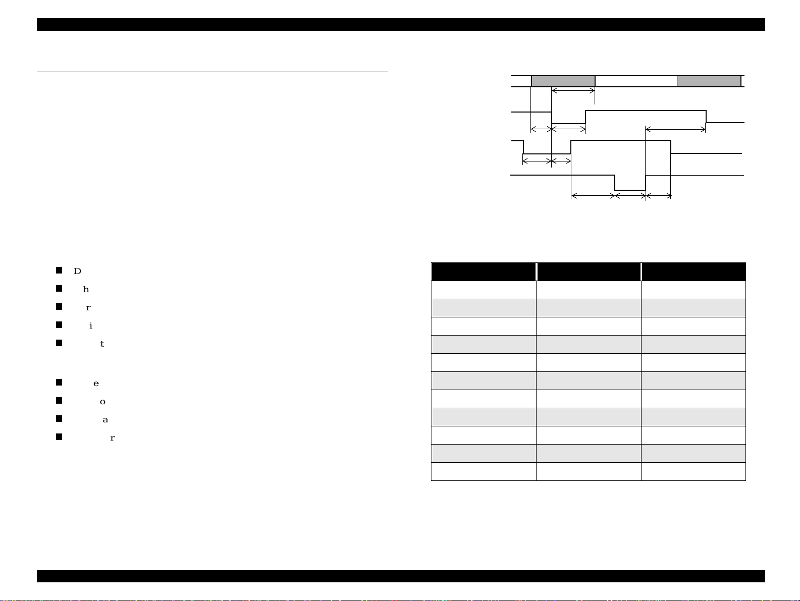
1.3.1 Parallel Interface (Forward Channel)
Transmission Mode: 8 bit parallel, IEEE-1284 compatibility m ode
Synchronization: By STROBE pulse
Handshaking: BY BUSY and ACKNLG signal
Signal Level: TTL compatible level
Adaptable Connector: 57-30360 (amphenol) or equivalent
BUSY signal is set high before setting either -ERROR low or PE high, and held high
until all these signals return to their inactive state.
BUSY signal is at high level in t he following cases:
n
During data entry (see data transmission timing).
n
When input data buffer is full.
n
During -INIT signal is at low level or during hardware initialization.
n
During printer error (see -ERROR signal).
n
When the parallel interface is not selected.
ERROR signal is at low le vel when the printer is in one of the following states:
n
Printer hardware error (fatal error)
n
Paper-out e rror
n
Paper-jam error
n
Ink-out error
PE signal is at high level during paper-out e rror.
DATA
-STROBE
tsetup
BUSY
tready
-ACKNLG
databyte n
thold
tbusy
treply
tstb
tack
tnbusy
Figure 1-3. Data Transmission Timing
Table 1-3.
Parameter Minimum Maximum
tsetup 500ns -
thold 500ns -
tstb 500ns -
tready 0 -
tbusy - 500ns
tt-out* - 120ns
tt-in** - 200ns
treply 0 -
tack 500ns 10us
tnbusy 0 -
tnext 0 -
databyte n+1
tnext
* Rise and fall time of every output signal.
** Rise and fall time of e very input signal.
*** Typical timing for tack is shown on the following page.
PRODUCT DESCRIPTION INTERFACE 14
Page 15
EPSON Stylus COLOR 680/777/777i Revision B
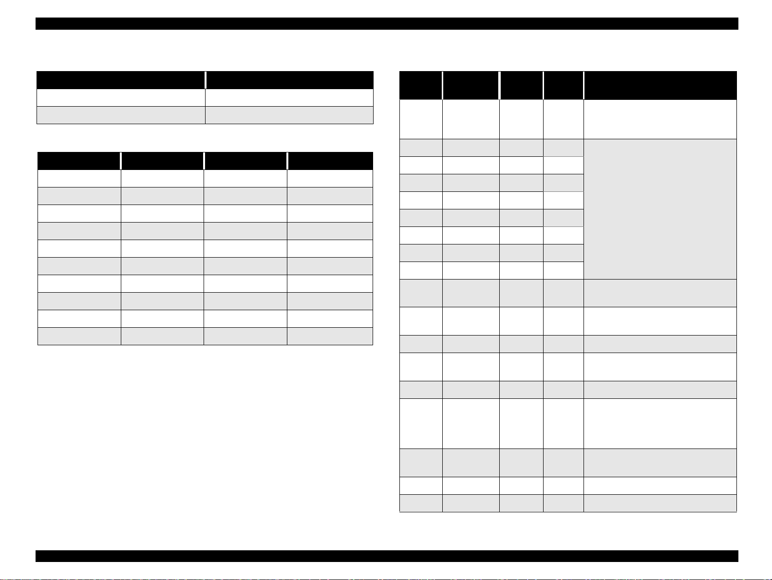
Table 1-4. Typical Time of tack
Parallel I/F Mode TypicalTime of tack
High Speed 0.5us
Normal Speed 2us
Table 1-5. Signal Level: TTL Compatible (IEEE-1284 level 1 d evice)
Parameter Minimum Maximum Condition
VOH* - 5.5V
VOL* -0.5V -
IOH* - 0.32mA VOH = 2. 4V
IOL* - 12mA VOL = 0.4V
CO - 50pF
VIH - 2.0V
VIL 0.8V -
IIH - 0.32mA VIH = 2.0V
IIL - 12mA VIL = 0.8V
CI - 50pF
* A low logic level on the Logic H signal is 2.0V or less when the printer
is powered off, and this signal is equal to or exceeding 3.0V whe n the
printer is powered on. The receiver shall provide an impedance
equivalent to 7.5K ohm to ground.
Table 1-6. Connector Pin Assignment and Signals
Pin No. Signal Name
1 -STROBE 19 In
2 DATA0 20 In
3 DATA1 21 In
4 DATA2 22 In
5 DATA3 23 In
6 DATA4 24 In
7 DATA5 25 In
8 DATA6 26 In
9 DATA7 27 In
10 -ACKNLG 28 Out
11 BUSY 29 Out
12 PE 28 Out A high signal indicates paper-out error.
13 SLCT 28 Out
14 -AFXT 30 In Not used.
Return
GND Pin
In/Out Functional Description
The strobe pulse. Read-in of data is
performed at the falling edge of this
pulse.
The DATA0 through DATA7 signals
represent data bits 0 to 7, respectively.
Each signali s at high level when datais
logical 1 and low level when data is
logical0.
This signal is a negative pulse indicating
that the printer can accept data again.
A high signal indicates that the printer
cannot receive data.
Always at high level when the printer is
powered on.
The falling edge of a negative pulse or a
31 -INIT 30 In
32 -ERROR 29 Out
36 -SLIN 30 In Not used.
18 Logic H - Out Pulled up to +5V via 3.9 K ohm resistor.
low signal on this line causes the printer
to initialize. Minimum 50us pulse is
necessary.
A low signal indicatesprinter error
condition.
PRODUCT DESCRIPTION INTERFACE 15
Page 16
EPSON Stylus COLOR 680/777/777i Revision B
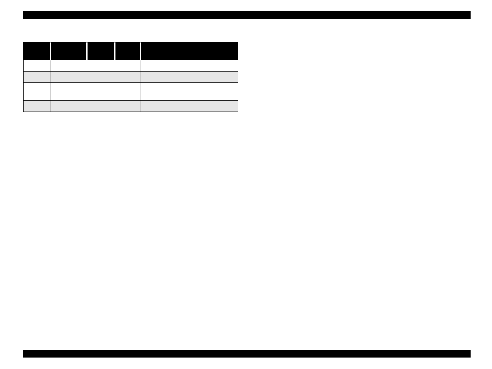
Table 1-6. Connector Pin Assignment and Signals (continued)
Pin No. SignalName
35 +5V - Out Pulledupto+5Vvia3.3Kohmresistor.
17 Chassis GND - - Chassis GND
16,33,
19-30
15,34 NC - - Not connected
GND - - Signal GND
Return
GND Pin
In/Out Functional Description
NOTE: In/Out refers to the direction of signal flow seen f rom the printer side.
PRODUCT DESCRIPTION INTERFACE 16
Page 17
EPSON Stylus COLOR 680/777/777i Revision B
1.3.2 Parallel Interface (Reserve Channel)
Transmission Mode: IEEE-1284 nibble mode
Adaptable Connector See forward channel.
Synchronization: Refer to the IEEE-1284 specification
Handshaking: Refer to the IEEE-1284 specification
Data Trans. T iming: Refer to the IEEE-1284 specification
Signal Level: IEEE-1284 level 1 device
See forward channel.
Table 1-7. Connector Pin Assignment and Signals
Pin No. Signal Name
1 HostClk 19 In Host clock signal.
2 DATA0 20 In
3 DATA1 2 1 In
4 DATA2 22 In
5 DATA3 2 3 In
6 DATA4 24 In
7 DATA5 2 5 In
8 DATA6 26 In
9 DATA7 2 7 In
10 PtrClk 28 Out Printer clock signal.
Return
GND Pin
In/Out Functional Description
The DATA0 through DATA7 signals
represent data bits 0 to 7, respectively.
Each signal is at high level when data is
logical1 and low level when data is
logical0.
These signals are used to transfer the
1284 extensibility request values to the
printer.
Table 1-7. Connector Pin Assignment and S ignals ( continued)
Pin No. Signal Name
32
36 1284-Active 30 In 1284 active signal.
18 Logic-H - Out Pulled up to +5V via 3.9K ohm resistor.
35 +5V - Out Pulled up to +5V via 3.3K ohm resistor.
17 ChassisGND - - Chassis GND
16,33,
19-30
15,34 NC - - Not connected
-DataAvail /
DataBit-0,4
GND - - Signal GND
NOTE: In/Out refers to the direction of signal flow from the printer’s point of
view.
Extensibility Request:
The printer responds affirmatively when the extensibilityrequest values are 00H or
04H, which means,
00H: Request Nibble Mode Reverse C hannel Transfer.
04H: Request Device ID;
Return Data Using Nibble Mode Rev Channel T ransfer.
Return
GND Pin
29 Out
In/Out Functional Description
Dataavailablesignaland reversechannel
transfer data bit 0 or 4.
11
12
13
14 HostBusy 30 In Host busy signal.
31 -INIT 30 In Not used.
PtrBusy /
DataBit-3,7
AckDataReq
/ DataBit-2,6
Xflag /
DataBit-1,5
29 Out
28 Out
28 Out
Printer busy signal and reverse channel
transferdata bit 3 or 7.
Acknowledge data request signal and
reverse channel transfer data bit 2 or 6.
X-flag signal and reverse channel
transferdata bit 1 or 5.
PRODUCT DESCRIPTION INTERFACE 17
Page 18
EPSON Stylus COLOR 680/777/777i Revision B
Device ID:
The printer s ends the following device ID string when requested.
When IEEE1284.4 is enabled,
[00H] [5AH]
MFG: EPSON;
CMD: ESCPL2, BDC, D4;
MDL: Stylus[SP]COLOR[SP]XXX*;
CLS: PRINTER;
DES: EPSON[SP]Stylus[SP]COLOR[SP]XXX*;
When IEEE1284.4 is disabled,
[00H] [57H]
MFG: EPSON;
CMD: ESCPL2, BDC;
MDL: Stylus[SP]COLOR[SP]XXX*;
CLS: PRINTER;
DES: EPSON[SP]Stylus[SP]COLOR[SP]860/1160;
*XXX is 777 (for EAI spec) or 680 (for EURO/ASIA spec)
Note 1: [00H] denotes a hexadecimal value of zero.
Note2: MDL value depends on the EEPROM setting.
Note3: CMD value depends on the IEEE1284.4 setting.
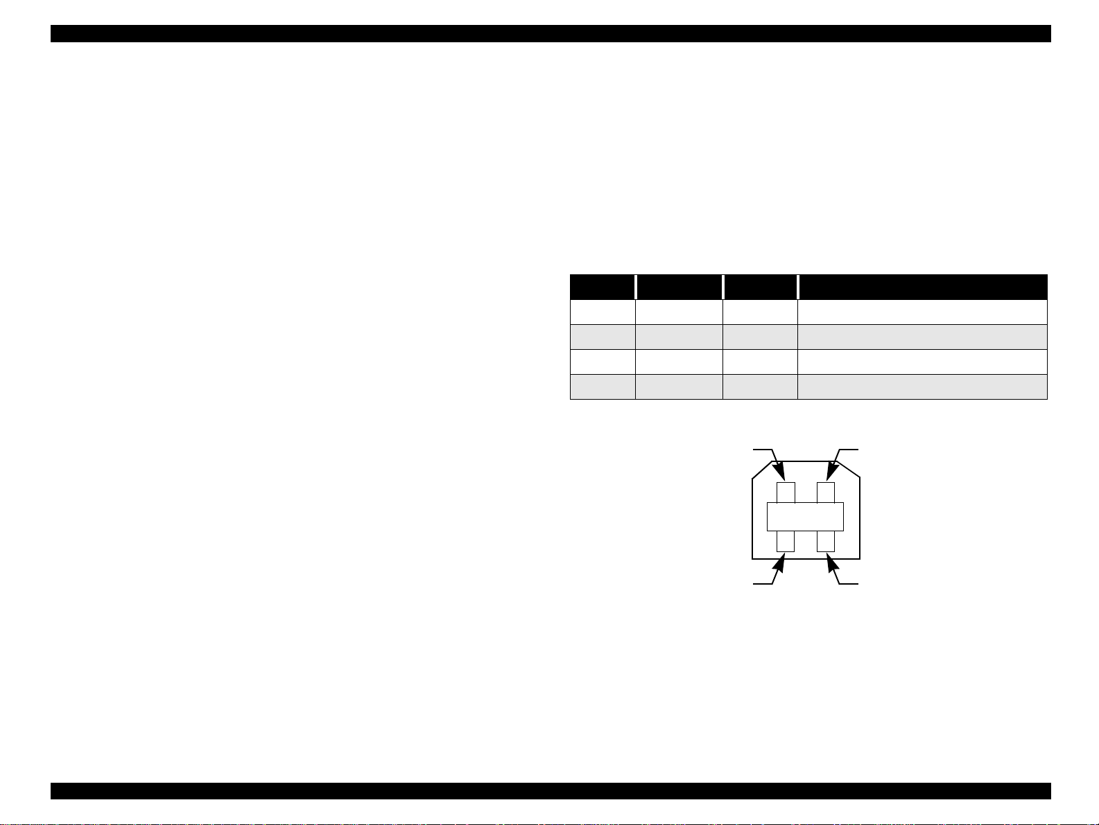
1.3.3 USB Interface
Standard: Based on:
“Universal Serial Bus Specifications Rev. 1.0”
“UniversalSerial Bus Device Class Definition
for Printing Devices Version 1.0”
Bit Rate: 12Mbps (Full Speed Device)
Data Encoding: NRZI
Adaptable Connector: USB Series B
Recommended Cable Length: 2 meters
Table 1-8. Connector Pin Assignment and Signals
Pin No. Signal Name I/O Function Description
1 VCC - Cable power. Max.power consumption is 2mA.
2 -Data Bi-D Da ta
3 +Data Bi-D Data, pull up to +3.3 V via 1.5K ohm resistor.
4 Ground - Cable ground
Pin #2
Pin #1
Pin #3
Pin #4
Figure 1-4. USB Pin Assignment
PRODUCT DESCRIPTION INTERFACE 18
Page 19
EPSON Stylus COLOR 680/777/777i Revision B
o
1.3.4 Prevention of Data Transfer Time-out
Generally,hosts abandon data transfer to peripherals when the peripheral is in the busy
state for dozens of seconds continuously. To prevent this kind of time-out, the printer
receives data very slowly, several bytes per minute, even if the printer is in the busy
state. The slowdown starts when the remaining input buffer becomes several hundreds
of bytes, and the printer finally gets into the busy state continuously when the input
buffer is full.
USB and IEEE1284.4 on the parallel interface do not require such function.
On
An initial state is IEEE1284.4communication and data that received it by thetime
it is able to take synchronization by magic string (1284.4 synchronous commands)
is discarded.
o
Off
An initial state is compatible interface and never starts IEEE1284.4
communication even if magic strings (1284.4 synchronous commands) are
received.
1.3.5 Interface Selection
The printer ha s two built-in interfaces: the USB and parallel interface.
These interfaces are selected automatically.
o
Automatic Selection
In thisautomatic interface selection mode, the printer is initialized to the idle state
while scanning which interface receives data when it is powered on. Then the
interface which received data first is selected. Whe n the host stops data transfer
and the printer is in the s tand-by statefor seconds,the printer is returned to the idle
state.As long as the host sends data or the printer interface is in the busy state, the
selected interface is let as it is.
o
Interface State and Interface Selection
When the parallel interface is not selected, the interface gets into the busy state.
When the printer is initialized or returned to the idle state, the parallel interface
gets into the ready state. Note that the interrupt signal such as the -INIT signal on
the parallel interface is not effective while that interface is not selected.
1.3.6 IEEE1284.4 Protocol
The packet protocol described by IEEE1284.4 standard allows a device to carry on
multiple exchanges or conversations which contain data and/or control information
with another device at the same timeacross a singlepoint-to-pointlink. The protocol is
not, however, a device control language. It does provide basic transport-level flow
controland multiplexingservices. The multiplexedlogical channels are independent of
each other a nd blocking of one has no effect on the others. The protocol operates over
IEEE1284.
o
Automatic Selection
An initial stateis compatible interface and starts IEEE1284.4 communication
when magic strings (1284.4 synchronous commands) are received.
PRODUCT DESCRIPTION INTERFACE 19
Page 20
EPSON Stylus COLOR 680/777/777i Revision B
O
1.4 OPERATOR CONTROLS
1.4.1 Operating Switch
Operating switch is located on the control panel.
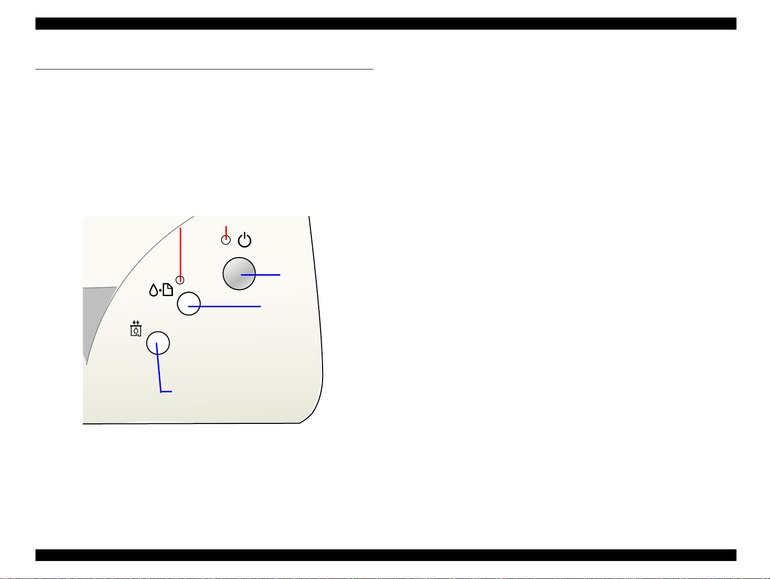
1.4.2 Control Panel
1.4.2.1 Switches
There are two non-lock type push switches, one lock-type push switch, and two LED
lights.
21
Power
Maintenance
1.4.2.2 Indicators
(1) Power
Lights when the operating switch is “ON” and AC power is supplied.
(2) Error
Lights or blinks when some error has occur to the printer.
Ink Cartridge replacement
Figure 1-5. Control Panel
PRODUCT DESCRIPTION
PERATOR CONTROLS 20
Page 21
EPSON Stylus COLOR 680/777/777i Revision B
O
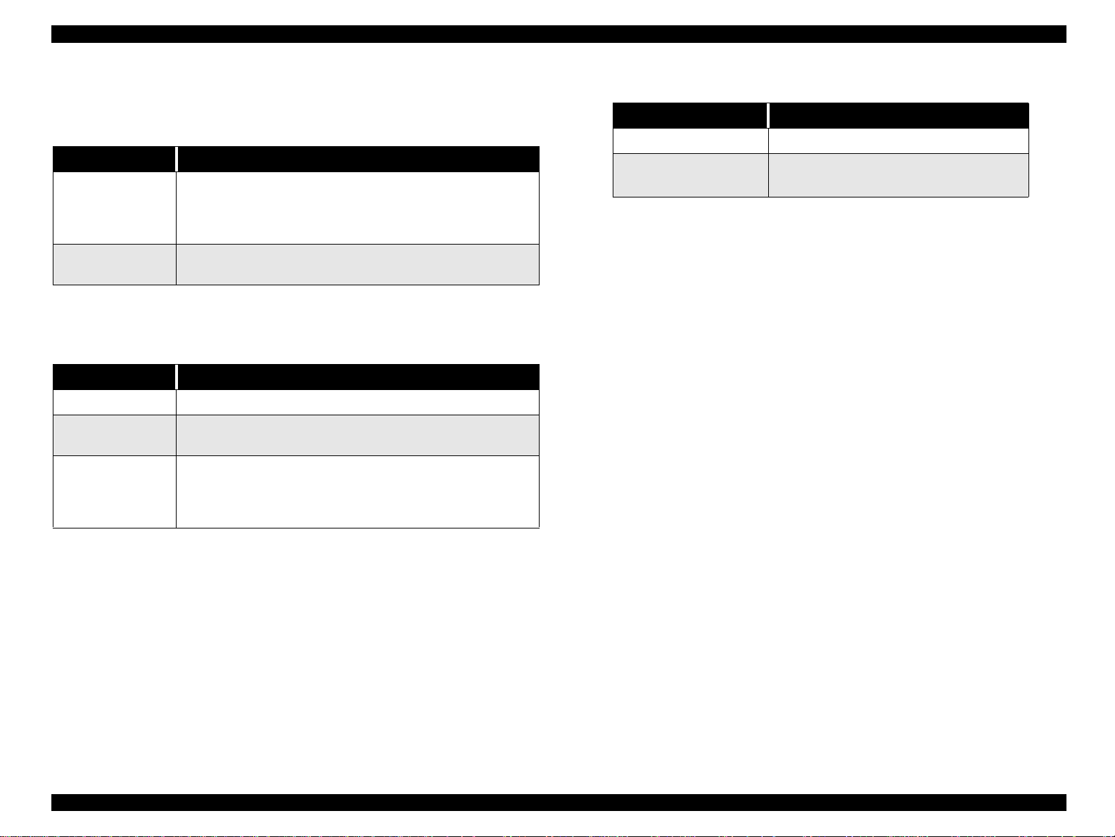
1.4.3 Panel Functions
Table 1-9. Panel Functions
Switch Function
Maintenance
Ink Cartridge
replacement
* This function is not available in printing status.
Switch Function
Maintenance
Ink Cartridge
replacement
Maintenance
+
Ink Cartridge
replacement
• Loads or Ejects the Paper (Pushing within 3seconds).
• Starts the Cleaning of head (Pushing for 3seconds).
• When carriage is on t he Ink Cartridgechange position, return
carriage from Ink Cartridge change position.
• Starts the Ink Cartridge change sequence. *
Table 1-10. Panel Functions with Power On
• Start status printings.
• Select IEEE 1284.4 mode for parallel I/F. *1
• Enters the special setting mode (Factory use only). *3
Table 1-11. Special S etting Mod e
Switch Function
Maintenance
Ink Cartridge replacement
(10 seconds)
.
• Initialize EEPROM.
• Reset the ink overflow counterin the
EEPROM.
*1 Not described in the user's manual.
*2 See the table
PRODUCT DESCRIPTION
PERATOR CONTROLS 21
Page 22
EPSON Stylus COLOR 680/777/777i Revision B
O
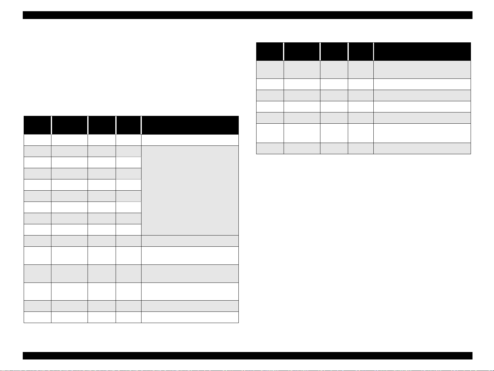
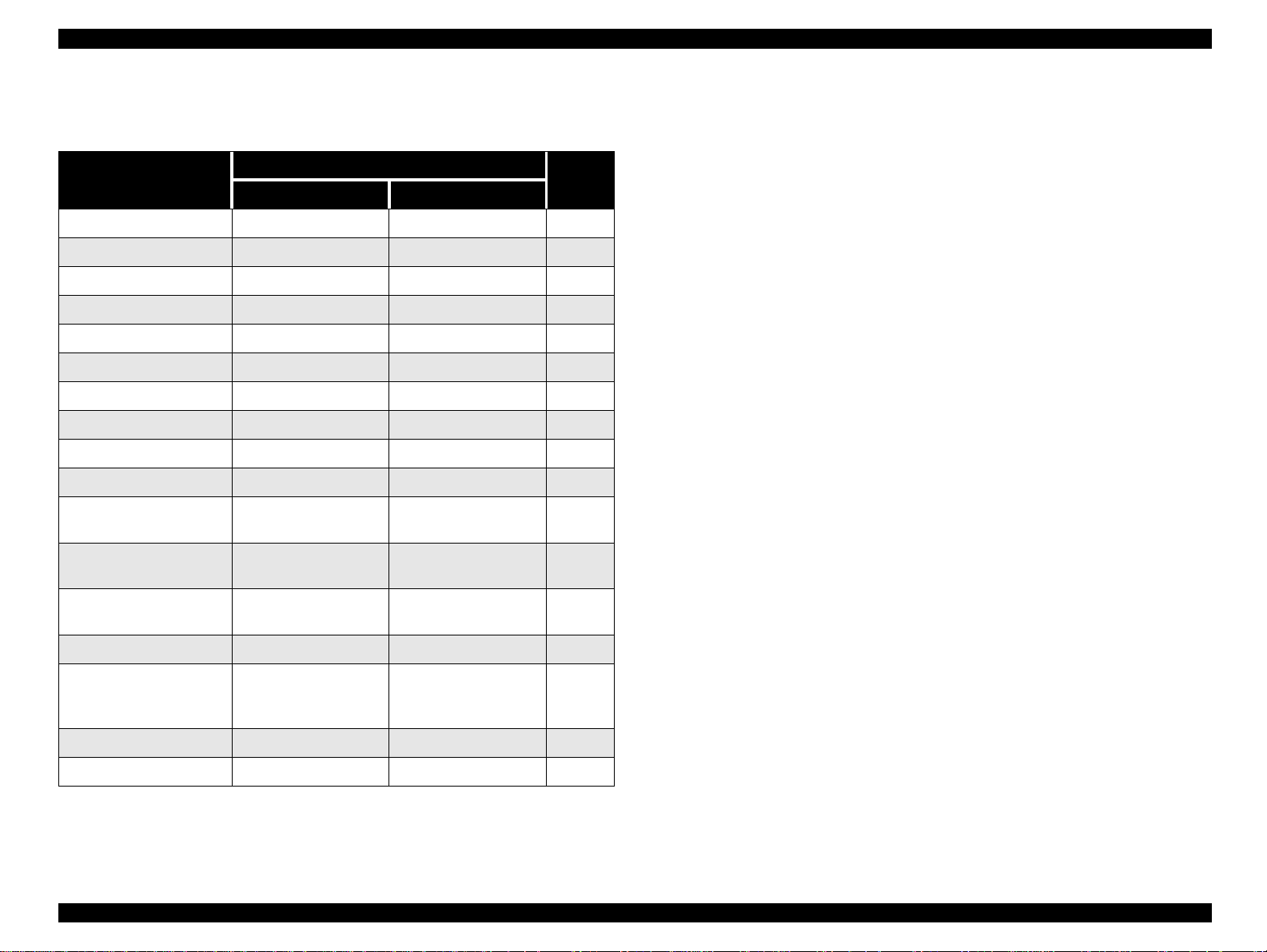
1.4.4 Printer Condition and Panel Status
Table 1-12. Printer Condition and LED S tatus
Printer Status
Power ON condition On - 10
Ink sequence Blink - 6
Ink Cartridge changemode Blink - 5
Data processing Blink - 9
Paper Out - On 4
Paper jam condition - On 3
Ink end (Black) - On -> Blink 8
Ink levellow ( Black) - Blink 8
Ink end (Color) - On -> Blink2 8
Ink level low (Color) - Blink 8
Ink end
(Black and Color)
No Ink Cartridge
(Black and Color)
Reset, Timer IC reset,
EEPROM clear
Ink Overflow Counter reset On (2s) On (2s) Maintenance request
(Ink Overflow Counter
error)
Power Er ror
- Blink -> Blink 8
- On 7
On (1s) On (1s) -
Alt Blink Alt Blink 2
Indicators
Priority
1.4.5 Printer Initialization
There are three kinds of initialization m ethods, and the following explains each
initialization.
1. Power-on Initialization
This printer is initialized when turning the printerpower on, or printer recognized
the cold-reset command (remote RS command).
When printer is initialized, the following actions are performed:
(a) Initializes printer mechanism.
(b) Clears input data buffer.
(c) Clears print buffer.
(d) Sets default values.
2. Operator Initialization
This printer is initialized when turning the printerpower on again within 10
seconds from last power off, or printer recognized the -INIT signal (negative
pulse) of parallel interface.
When printer is initialized, the following actions are performed:
(a) Cap the printer head.
(b) Eject a paper.
(c) Clears input data buffer.
(d) Clears print buffer.
(e) Sets default values.
3. Software Initialization
The ESC@ command also initialize the printer.
When printer is initialized, the following actions are performed:
(a) Clears print buffer.
(b) Sets default values.
Fatal error Off On 1
Specialsetting Blink Blink -
" - " : Indicator status don't change.
" A -> B " : A is a indicator condition when carriage is on Home Position.
B is a indicator conditionin Ink exchange sequence.
PRODUCT DESCRIPTION
PERATOR CONTROLS 22
Page 23

EPSON Stylus COLOR 680/777/777i Revision B
O
1.4.6 Errors
o
Ink Out
When the printer runs out most of the ink of any color, it indicates ink-low and
keeps printing. When the printer runs out the whole ink of any color, it stops
printing and indicates ink-out error. User is then requested to install a new inkcartridge in this state. An ink-cartridge that has be en taken out once should never
be used again. Re-installationof the cartridge not filled fully upsets the ink level
detection and may eventually cause a serious problem in the print head.
o
Paper Out
When the printer fails to load a sheet, it goes into a paper out error.
o
Paper Jam
When the printer fails to eject a sheet, it goes into a paper jam error.
o
No Ink-Cartridge
When the printer detects that ink-cartridge comes off, or failed to read or write
CSIC data, it goes into this error mode.
o
Maintenance Request
When the total amount of ink wastedthrough cleanings and flushing reachesto the
limit, printer indicates this error and stops. In such a case, the absorber in the
printer enclosure needs to be replaced with new one by service personnel.
o
Fatal Errors
Carriage control error.
PRODUCT DESCRIPTION
PERATOR CONTROLS 23
Page 24

EPSON Stylus COLOR 680/777/777i Revision B
1.5 PAPER
1.5.1 Paper Handling
Do not perform reverse feed more than 1.8mm (0.07”).
1.5.2 Paper Specification
1.5.2.1 Cut Sheet
[Size]
A4: Width 210mm (8.3”) x Length 297mm (11.7”)
A5: Width 148mm (5.8”) x Length 210mm (8.3”)
A6: Width 105mm (4.1”) x Length 148mm (5.8”)
Letter: Width 216mm (8.5”) x Length 279mm (11.0”)
Half Letter: Width 139.7mm (5.5”) x Length 216mm (8.5”)
B5: Width 182mm (7.2”) x Length 257mm (10.1”)
Legal: Width 216mm (8.5”) x Length 356mm (14.0”)
Executive: Width 184.2mm (7.25”) x Length 266.7mm (10.5”)
[Thickness]
0.08mm (0.003”) - 0.11mm (0.004”)
[Weight]
2
64g/m
[Quality]
(17Ib.) - 90g/m2(24Ib.)
1.5.2.2 Transparency, Glossy Paper
[Size]
A4: Width 210mm (8.3”) x Length 297mm (11.7”)
Letter: Width 216mm (8.5”) x Length 279mm (11.0”)
[Thickness]
0.075mm (0.003”) - 0.085mm (0.0033”)
[ASF hopper availablecapacity]
1sheets
Note: Transparency printing is available only at normal temperature.
1.5.2.3 Envelope
[Size]
No.10: Width 241mm (9 1/2”) x Length 104.8mm (4 1/8”)
DL: Width 220mm (8.7”) x Length 110mm (4.3”)
C6: Width 162mm (6.4”) x Length 114mm (4.5”)
[Thickness]
0.16mm (0.006”) - 0.52mm (0.02”)
[Weight]
45g/m2(12Ib.) - 75g/m2(20Ib.)
Exclusive paper, Bond paper, PPC
[ASF hopper available capacity]
100 sheets
Note1: No wrinkled, scuffing, torn or folded paper be used.
Note2: No curled paper more than 5 mm be used.
PRODUCT DESCRIPTION PAPER 24
Page 25

EPSON Stylus COLOR 680/777/777i Revision B
[Quality]
Bond paper, Plain paper, Air mail
Note1: Envelope printing is available only at normal temperature.
Note 2: Keep the longer side of the envelope horizontally at setting.
Note 3: Envelope printing is available only in t he normal temperature.
Note 4: No wrinkled,scuffing, torn or folded paper be used.
Note 5: No curled paper more than 5mm be used.
Note 6: No paper with glue on flap be used.
Note 7: No double envelops nor with window envelops be used.
Note 8: Do not print on the back.
1.5.2.4 Index Card
[Size]
A6 Index Card: Width 105mm (4.1”) x Length 148mm ( 5.8”)
A5 Index Card: Width 148mm (5.8”) x Length 210mm ( 8.3”)
5 x 8” Index Card: Width 127mm (5.0” x Length 203mm (8.0”)
10 x 8” Index Card: Width 127mm (5.0”) x Length 203mm (8.0”)
[Thickness]
Less than 0.23mm (0.0091”)
[ASF hopper available capacity]
30 sheets
PRODUCT DESCRIPTION PAPER 25
Page 26
EPSON Stylus COLOR 680/777/777i Revision B
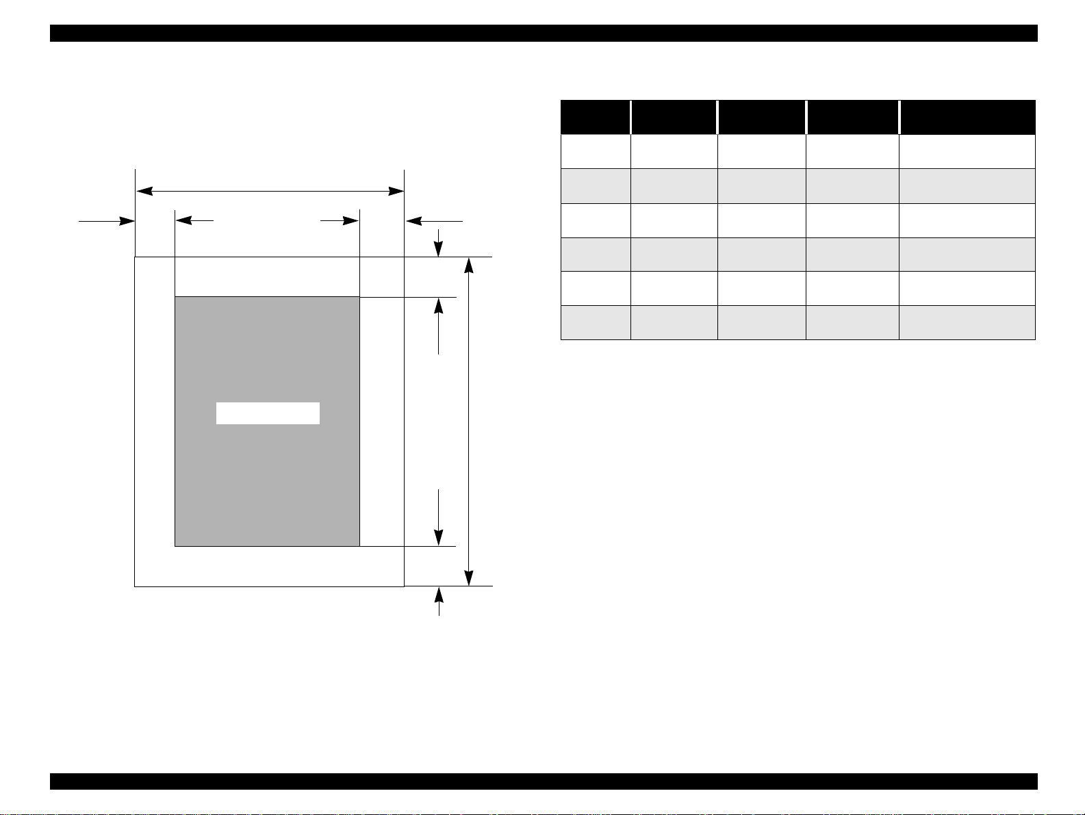
1.5.3 Printing Area
1.5.3.1 Cut Sheet
See the figure be low and tables on the right for printable areas.
PW
LM
Printable Area
RM
TM
PL
Table 1-13. Printing Area
Left Margin
Paper Size
A4 3 mm (0.12”) 3 mm (0.12”) 3 mm (0.12”)
Letter 3 mm (0.12”) 3 mm (0.12”) 3 mm (0.12”)
B5 3 mm (0.12”) 3 mm (0.12”) 3 mm (0.12”)
Legal 3 mm (0.12”) 3 mm (0.12”) 3 mm (0.12”)
Statement 3 mm (0.12”) 3 mm (0.12”) 3 mm (0.12”)
Exclusive 3 mm (0.12”) 3 mm (0.12”) 3 mm (0.12”)
(min.)
* Bottom margin can be reduced to 3mm when paper dimension is
defined by using command, otherwise it is not reduced (14mm). As for
an area between 3mm and 14mm margin, printing quality may decline.
** Refer to 1.5.2 Paper Specification for PW (paper width) and PL
(paper length).
Right Margin
(min.)
Top Margin
(min.)
14 mm (0.54”)/ 3mm
(0.12”) *
14 mm (0.54”)/ 3mm
(0.12”) *
14 mm (0.54”)/ 3mm
(0.12”) *
14 mm (0.54”)/ 3mm
(0.12”) *
14 mm (0.54”)/ 3mm
(0.12”) *
14 mm (0.54”)/ 3mm
(0.12”) *
Bottom Margin
(min.)
BM
Figure 1-6. Printable Area for Cut S heet
PRODUCT DESCRIPTION PAPER 26
Page 27
EPSON Stylus COLOR 680/777/777i Revision B
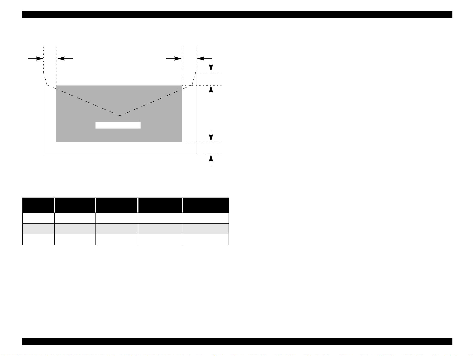
1.5.3.2 Envelopes
LM
RM
TM
Printable Area
BM
Figure 1-7. Printable Area for Envelopes
Table 1-14. Envelope Margin
Size
#10 3 mm (0.12”) 28 mm (1.10”) 3 mm (0.12”) 14 mm (0.55”)
Left M a rgin
(min.)
Right M argin
(min.)
Top Margin
(min.)
Bottom Margin
(min.)
DL 3 mm (0.12”) 7 mm (0.28”) 3 mm (0.12”) 14 mm (0.55”)
C6 3 mm (0.12”) 3 mm (0.12”) 3 mm (0.12”) 14 mm (0.55”)
PRODUCT DESCRIPTION PAPER 27
Page 28
EPSON Stylus COLOR 680/777/777i Revision B
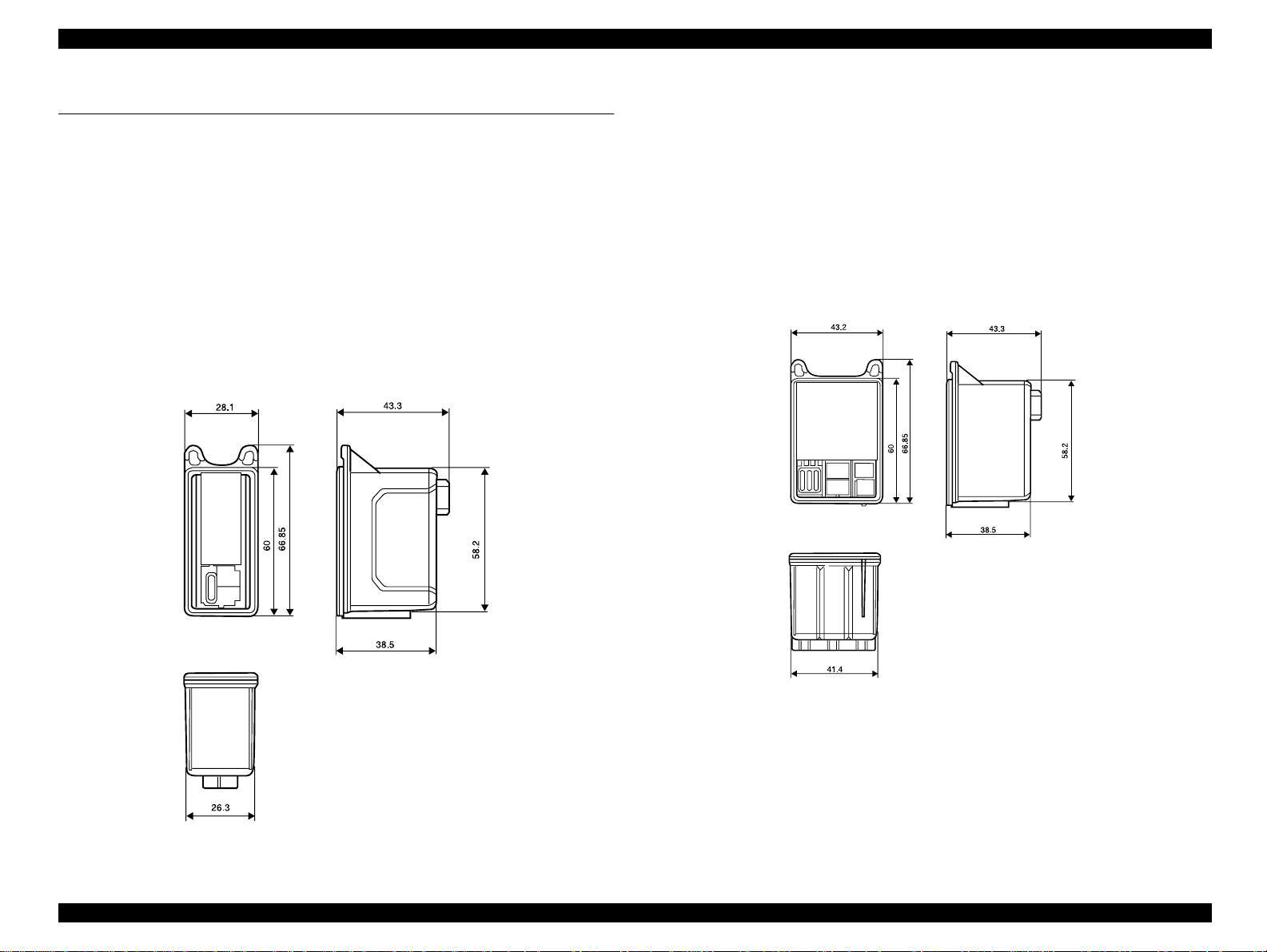
1.6 INK CARTRIDGE
1.6.1 Black Ink Cartridge
Type: Exclusive Cartridge
Color: Black
Print Capacity: 600 pages/A4
(ISO/IEC 10561 Letter Pattern at 360 dpi)
Ink Life: 2 years from date of production
Storage Temperature:
Storage: -20
Packing: -30
Transit: -30
Dimension: 28.1 mm (W) x 66.85 mm (D) x 43.3 mm (H)
o
Cto40oC (within a month at 40oC)
o
Cto40oC (within a month at 40oC)
o
Cto60oC (within 120 hours at 60oC
and within a month at 40
o
C)
1.6.2 Color Ink Cartridge
Type: Exclusive Cartridge
Color: Magenta, Cyan, Yellow
Print Capacity: 300 pages / A4 (360 dpi, 5% duty each color)
Ink Life: 2 years from date of production
Storage Temperature:
Storage: -20
Packing: -30
Transit: -30
Dimension: 43.2 mm (W) x 66.85 mm (D) x 43.3 mm (H)
o
Cto40oC (within a month at 40oC)
o
Cto40oC (within a month at 40oC)
o
Cto60oC (within 120 hours at 60oC
and within a month at 40
o
C)
Figure 1-9. Color Ink Cartridge
Note 1: Ink cartridge can not be refilled. The ink cartridge is prepared only
for article of consumption.
Note 2: Do not use the ink cartridge which c ontains life-expired ink.
Note 3: Ink will be frozen under -4
o
C environment; however, it will be
usable after being left at room temperature for more than three
Figure 1-8. Black Ink Cartridge
hours.
PRODUCT DESCRIPTION INK CARTRIDGE 28
Page 29

OPERATINGPRINCIPLES
CHAPTER
2
Page 30
EPSON Stylus COLOR 680/777/77i Revision B
O
2.1 Overview
This section describes the operating principles of the printer m echanism and electrical
circuit boards.The Stylus COLOR 680/777/777i has the following boards:
o
Main board: C383 MAIN (C383 MAIN-B)
NOTE: C383 MAIN-B is compatible with C383 MAIN. Only some chips or parts
are differentfrom each other due to different producers.
o
Power supply board: C383 PSB/PSE
o
Panel board: C383 PNL
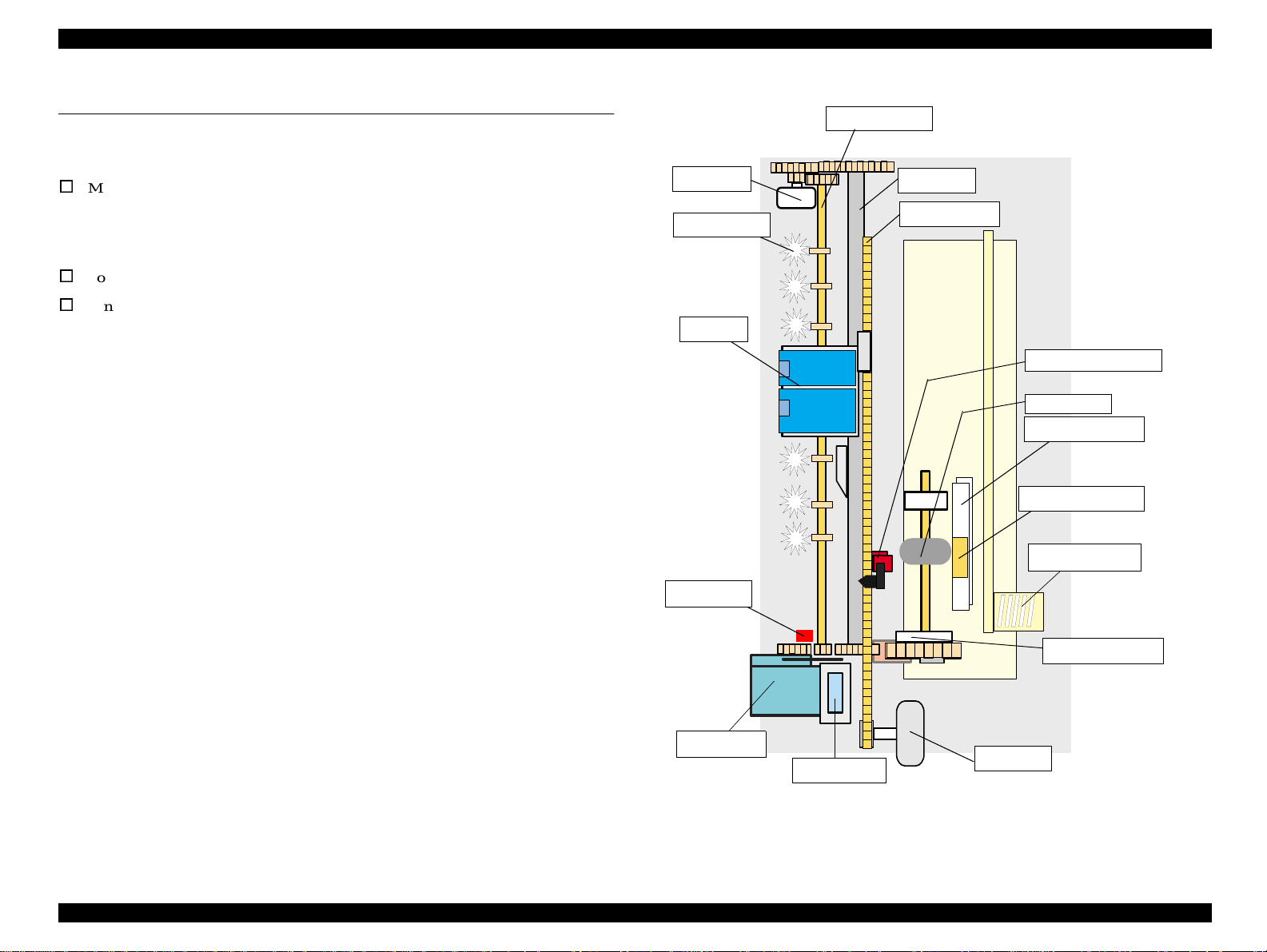
2.1.1 Printer Mechanism
The printer m echanism for Stylus COLOR 680/777/777i is designed newly. But, the
basic component of the printer mechanism is same as previous product.
This printer consists of Print Head, Carriage Mechanism, Paper Feeding Mechanism,
Paper Loading Mechanism, Ink System (Pump Mechanism, Cap Mechanism, and
Carriage Lock Mechanism).
Like other E PSON ink jet printers, the Stylus COLOR 680/777/777i is equipped with
two stepping motors; one for ASF, Paper feeding/ Pump m echanism, and one for CR
mechanism.ASF unit uses rear entry front eject system. This ASF unit is also designed
newly and single LD roller loads the paper to the printer mechanism.
PF Motor
Star Wheel Roller
CR unit
Paper Eject Roller
PF Roller
CR Timingbelt
HP/PE/IC Sensor sensor
LD Roller
Paper feed back plate
Paperseparationpad
ASF Hopper Spring
For cap assembly,Stylus COLOR680/777/777iuses valvelessmechanism;new design
CR lock lever
for this model.
Clutch mechanism
Pump Assembly
Cap Assembly
CR Motor
Figure 2-1. Printer Mechanism block diagram
Operating Principles
verview 30
Page 31

EPSON Stylus COLOR 680/777/77i Revision B
O
2.1.2 Printhead
The printhead uses a new developed U-CHIPS head and Stylus COLOR 680/777/777i
can perform multiple shot printing and variable printing.
The CSIC is mounted on the ink cartridge. By storing ink life data, this IC makes it
possible to control the ink in ink cartridge unit.
The basic operating principles of the printhead, which plays a major role in printing,
are the same as previous models; on-demand m ethod which uses PZT (Piezo Electric
Element). In order to uniform the amount of ejecting ink, the printhead has its own
head ID (6 digits for this printhead) which adjust PZT voltage drive features.
The printhead stores the head ID to EEPROM and generates appropriate PZT drive
voltage to prevent amount of ink from varying by printheads.
Following explains printhead basic components.
o
PZT
PZT is an abbreviation of Piezo Electric Element. Certain amount of voltage
expandsand contracts PTZ. The drive wave generated on MAIN board drives PZT
and P ZT pushes the top c avity which has ink stored to discharge the ink from each
nozzle on the nozzle plate.
o
Ink Cavity
The ink absorbed from the ink cartridge goes through the filter and then is stored
temporarily in this tank called “cavity” until PZT is driven.
Nozzle Plate
Ink Cartridge
PZT
CSIC
Needle
Cavity
Nozzle Selector Board
CSIC Connection Circuit
Filter
Figure 2-2. Printhead S ectional Drawing
o
Nozzle Plate
The board with nozzle holes on the printhead surface is called Nozzle Plate.
o
CSIC Connection Circuit
This circuit connects the CSIC mounted on the ink cartridge and the main board.
One end of the wire harness connectswith the print head cable to the main board.
o
Filter
When the ink cartridgeis installed, if any dirt or dust aroundthe cartridgeneedle is
absorbed into the head, there is a great possibility of causing nozzle clog and
disturbance of ink flow, and finally causing alignment failure and dot missing. To
prevent this problem, a filter is setbelow the cartridge needle,where ink is filtered.
Operating Principles
verview 31
Page 32

EPSON Stylus COLOR 680/777/77i Revision B
O
2.1.2.1 Printing Process
This section explainsthe processin which the printheads of On-Demand inkjet printers
eject ink from each nozzle.
1. Normal State:
When no printing signal is sent from PC, or no PZT drive voltage is applied, PZT
does not change s hape, therefore PZT does not squeeze the cavity. Ink pressure
inside the cavity is kept normal. (Refer to Figure 2-3.)
2) Ejecting State:
When the print signal is output from the C383 MAIN board, IC (Nozzle Selector)
located on the printhead unitlatches data once by 1-byte unit. An a ppropriate PZT
latched by the nozzle selectoris pushed into the cavity by the common voltage
applied from the m ain board. By this operation, ink stored in the cavity spurts out
from nozzles.(Refer to Figure 2.1.2.2.)
Ink Path
Nozzle
PZT
Ink Cavity
Nozzle plate
2.1.2.2 Printing Method
For print dot system, StylusCOLOR 680/777/777i has the following two kinds of
printing modes.
n
Multiple shot printing
n
Variable dot printing
The above two printing modes are automatically selected depending on the media and
the resolution setting of the printer driver. T he following explains each printing mode.
o
Multiple shot printing
This printing mode is de veloped to improve the print quality on plain paper or
transparencies in low resolution.The multiple shot printing mode uses normal dot
and the number of dot shots varies from 1 shot to maximum 4 shots depending on
the print data to enable s harp image output even in a low resolution.
o
Variable dot printing
This printing mode is de veloped to improve the print quality on e xclusive paper.
This mode is basically the same as variable dot printing mode used on other
products /; micro dot, m iddle dot, and large dot compose this mode. Print dot size
varies according to print data and this mode enables even sharper image output on
exclusive paper.
PZT drive voltage
Figure2-3. Printhead printing process
Operating Principles
verview 32
Page 33

EPSON Stylus COLOR 680/777/77i Revision B
O
2.1.3 Carriage Mechanism
The carriage mechanism consists of Carriage motor (CR motor), Carriage unit
(including printhead), CR timing belt, CR guide shaft, CR guide frame, CR home
detector (HP /PE sensor) etc. The carriage mechanism moves the carriage back and
forth according to the drive from the carriage motor. The following stepping motor is
mounted to drive C R mechanism. (See the table below.)
Table 2-1. Carriage Motor Specification
Items Specifications
Type 4-Phase/ 200-Pole HB Stepping motor
Drive Voltage +42 V +/ - 5% (DRV IC voltage)
Coil Resistance 7.8 Ω +/ - 10% (per phase at 25 degree)
Inductance 14 mH +/ - 20%(1KH 1VmA)
Drive Method Bi-Polar drive
Driver IC LB11847
The drive from CR motor is transferred to the CR unit via CR timing belt. And the CR
home position is detected with the HP/PE sensor. This sensor is available as CR HP
detector only in the HP (home position)detection sequence & pump operation
sequence. (not available in the paper feeding sequence for the CR HP detector because
it is used for only PE sensor during the paper feeding sequence.) Moreover, unlike the
previous products, this printer dose not have the PG adjustment mechanism (1.7mm).
CR home position is detected with the HP/PE/IC sensorand the detection plate molded
in the CR unit as following figure. When the CR home position is detected with this
sensor, HIGH signal i s output to the CPU.
HP detection Lever
CR HP detection plate
Low signal
Right side view
CR HP detection plate
HP/IC detection Lever
High signal
Figure 2-5. CR home position
CR unit
HP/PE Sensor
CR Guide shaft
CR Motor
CR Timing belt
Figure 2-4. Carriage M echanism (Top view)
Operating Principles
verview 33
Page 34

EPSON Stylus COLOR 680/777/77i Revision B
O
2.1.4 Paper Feeding Mechanism
The paper feeding mechanism consists of Paper feed motor (PF motor), PF roller,
Paper eject roller, Star wheel roller, and so on. The paper feeding mechanism feeds
paper loaded from ASF using the PF roller and Paper E ject Roller & Star wheel roller.
For this mechanism, the PF motor mentioned in the right Table 2-2 is used on this
product.
The drive of the PF motor is transfer to the PF roller and the Paper Eject R oller as
following Figure 2-6. Following shows you how to transfer the PF motor drive to the
PF rollerand the Paper E ject Roller.
o
PF motor drive transmission path
PF Motor PinionGear (CW)
(CW) → Spur Gear 15 (CCW) →
(CCW) →
Spur gear 35.2(CW)
→ Combination Gear 16, 21.6 (CCW) → Spur Gear 73.6
Combination Gear 37.6, 44.4 (W) → Spur Gear 23.2
Table 2-2. PF Motor Specifications
Item Description
Motor type 4-Phase/ 200-Pole HB Stepping motor
Drive voltage +42 V +/ - 5% (DRV IC voltage)
Coil Resistance 7.8 Ω +/ - 10% (per phase)
Inductance 13.5 mH + / - 20%(1kH 1Vrms)
Driving method Bi-Polar drive
Driver IC LB11847
Spur Gear 35.2
PF roller
Spur Gear 23.2
Spur Gear 15
Combination gear
37.6, 44.4
Figure 2-6. Paper Feeding Mechanism
Paper loaded from ASF is advanced by the following roller.
o
Paper feed roller & Paper guide roller(assembled on the Top Frame) → Paper
eject roller & Star wheel roller (assembled on the Paper eject frame).
Operating Principles
Additionally, the top & end of the paper is detected with the HP/PE sensor.
In case the PE sensor dose not detect the paperin the paper loading sequence, the
printer detects the “Paper out error”. If the paper is detected after complete the paper
eject sequence, the printer detects the “Paper jam error”.
verview 34
Page 35

EPSON Stylus COLOR 680/777/77i Revision B
O
o
2.1.5 Paper Loading Mechanism (ASF Uni t)
The Paper loading mechanism is positioned at the printer rear. The Paper loading
mechanism loads paper at the ASF unit and fe eds paper to the PF roller.
This ASF unit was designed newly for t his product and consists of LD roller, Pad
holder (Paper return plate), ASF Frame, Hopper, and so on.
For the major feature of this ASF unit, ASF HP s ensor is not used and the single LD
roller is built in the ASF unit.
Drive sent from the PF motor is always transmitted to the ASF unit side. But, the
Change leverand the Clutch mechanism switch ON/OFF the PF motor drive to t he LD
roller with the motor rotational direction.
Drive from the PF motor is transmitted to the ASF unit as described below:
o
Switch the PF moto r drive to ASF unit side
PF Motor pinion gear rotatesCCW direction with a specific steps
Gear 16, 21.6 (CW)
→ Spur Gear 73.6(CCW) → Spur Gear 15(CW) →
Combination Gear 37.6, 44.4 (CCW) → Change Lever rotates (CCW) → Release
the Clutch mechanism lock position
Following F igure 2-7 shows you the switching path for PF motor drive to ASF unit
side.
→ Combination
Transfer the PF motor drive to LD roller
PF Motor pinion gear rotates CW direction
→ Spur Gear 73.6 (CW) → Spur Gear 15 (CCW) → Combination Gear 37.6, 44.4
(CW)
→ Change Lever rotates (CW) → Spur Gear 23.2 (CCW) → Spur Gear35.2
→ Combination Gear 16, 21.6 (CCW)
(CW) (include the clutch mechanism) → LD roller (CW).
Following Figure2-9 shows the PF motor drive transmission path to the LD roller unit
built in the ASF unit. The LD rolleris assembled on the same shaft that the Spur gear
35.2 is assembled.
Spur Gear 35.2
ChangeLever
Spur Gear 15
Spur Gear 23.2
CombinationGear
37.6, 44.4
Figure 2-8. PF motor drive transmission path
Spur Gear 35.2
Change Lever
Spur Gear 23.2
Spur Gear 15
Combination Gear
37.6, 44.4
When the PF motor torque is switched to the ASF unit side by the clutch mechanism,
the function of the ASF mechanism varies depending on the rotational direction of the
PF motor, as shown in the table below.
Table2-3. ASF unit function & PF Motor rotational direction
Directions Corresponding Functions
Clockwise (*1)
Counterclockwise (*1)
• Picks up and loads paper
• Release the DE lever & Clutch mechanism
Figure 2-7. Switch the PF motor drive to ASF unit side
(*1): The PF Motor rotational direction = seen from the right side of the printer.
o
Clutch Mechanism
Unlike the previous products, this product dose not have a ASF HP sensor.
Instead of the ASF HP sensor, Change lever and the Clutch mechanism are used to
detect the ASF home position. Following figures describe the mechanism.
Operating Principles
verview 35
Page 36

EPSON Stylus COLOR 680/777/77i Revision B
O
NOTE:
TheClutchgearismoldedon
thebacksideoftheSpurgear
35.2such as Combinationgear.
Spur gear 35.2
Clutch lever
Step1
Change Lever
Clutch gear
Clutch
Figure 2-9. Disengage & Clutch mechanism
The Clutch mechanism transmits the PF motor drive to the LD roller shaft only when
the Clutch gear rotates CW direction after the Change lever releases the Clutch lever. If
the Clutch gear rotates CCW direction, the PF motor drive is not transmitted to the LD
roller. This is due to the combination of the shape of the Clutch gear and the C lutch
lock tooth such as described on the figure.
1. When the paper is advanced with the P F roller, the Change lever is set on the
Clutch lever and the Clutch is pushed down as above Step1’s figure. As the
result, the Clutch gear (*1) is released from the Cluck lock tooth and the drive
from the PF motor is not transmitted to the LD roller shaft.
2. When the PF pinion gear rotates CCW direction in the above Step2’s figure, the
Change lever moves to the left direction with the CCW rotation of Combination
gear 37.6, 44.4. The Clutch turns back to the engagement position by the tension
force of the Tension spring 0.143 and the Clutch gear is engaged with the Clutch
lock tooth as above Step2’s center figure.
3. When the PF pinion gear rotates CW direction in the above Step3’s figure, the
Change lever moves to the right direction with the CW rotation of the
Combination gear 37.6, 44.4. Andthe drive from the PF motor is transmittedto the
LD roller shaft via C lutch gear and Clutch lock tooth.
4. The LD roller shaft rotates about 360 degree and the Change lever push the Clutch
lever a nd the PF motor drive is interrupted. This position is the ASF home
position.
Step2
Tension spring 0.143
Clutch lock tooth
Step3
LD roller shaft
Unlike the previous products, The Paper return plate is built in the ASF frame instead
of the Paper return lever. The Paper s eparation pad is also stacked on the plate.
It works with the spring force of the Torsion spring 25.7 (mounted in the ASF frame)
as following figure.
Hopper
Compression spring 4.80
ASF frame
LD roller
Paper Return
Plate
Torsion spring 25.7
Figure 2-10. Paper R eturn Plate
The Paper return plate is set to return the paper to the paper stand-by position in the
ASF unit when the ASF unit is in the standby mode. When the paper is fed with the
LD roller, the Paper return plate is stored in the ASF frame by the LD roller.
Following figures show you the ASF paper loading sequence and the operation of the
each mechanism.
o
Paper Return Plate (Pad hold er)
Operating Principles
verview 36
Page 37

EPSON Stylus COLOR 680/777/77i Revision B
O
When the paper is advanced with
the PF roller, Change lever push
down the Clutch lever as right
figure and the Clutch lock tooth is
disengaged from theClu tch gear.
As the result, the drive from the PF
motor is interrupted and the LD
roller dose not rotate.
This position is the ASF home
position.
The Paper return plate is set to
avoidthat the paper is slipped
down from the paper set position.
The PF motor piniongear rotates
CW direction and the drive from the
PF motor is transmitted to the ASF
LD roller shaft through the Clutch
lock tooth and the Clutch gear.
The ASF hopper release lever rotates
with the ASF LD roller and release
the ASF Hopper. The ASF hopper is
pushed with the Compression spring
4.80 and the paper is pickedup with
theASF LD roller.
LD roller
LD roller shaft
Paper return plate
PF motor pinion
gearCW rotation
ASF Hopper
release lever
Clutch lever
Step 1
Changelever
Step 3
Clutch gear
Clutch lock tooth
Clutch
LD roller shaft
Hopper
Compression
spring 4.80
Printer front side
PF motor pinion
gear CCW rotation
ASF Frame
Step 2
Tension spring 0.143
Step 4
Paper return plate
When the paper is loaded (pick up) from
the ASF unit, the Change lever moves to
the printer front side with the CCW
rotation of the PF motor pinion gear and
releases the Clutch lever. As the result,
the Clutch turns back to the engagement
position by the tension force of the
Tension spring 0.143.
And the Cl utch lock tooth is engaged
with the Clutch gear as right figure.
The ASF LD roller rotates CW direction
moreover and the Paper return plate is
stored under the ASF frame.
The paper is ad vanced up to the PF roller.
and the ASF LD roller & the clutch rotate
to the “Step1” position. The Clutch lever
is locked with the Change lever.
The drive from the PF motor is
interrupted and the drive is transmitted to
the PF roller side.
PF motor pinion
gearCW rotation
ASF hopper
releaselever
PF motor pinion
gear CW rotation
Figure2-11. ASF Paper Loading Sequence
Operating Principles
verview 37
Page 38

EPSON Stylus COLOR 680/777/77i Revision B
O
2.1.6 Ink System Mech anism
Ink system mechanism consists of pump unit (include the CR lock lever) and c apping
mechanism. Ink system mechanism drives the pump unit that presses cap to the
printhead and ejects ink from ink cartridge, head cavity and cap to the waste ink pad.
2.1.6.1 Pump Unit & Wiper mechanism
The pumpunit is driven by PF motor. PF motor drive is always transmitted to the paper
feeding mechanism and pump unit through the following gears. Refer to the Figure
2-13.
PF Motor Pinion Gear (CW)
→ Spur Gear 15 (CCW) → Combination Gear 37.6, 44.4 (CW) → Spur Gear 36.8 (CCW) →
Combination Gear 9.6,24 (CW)→ Pump Unit Gear (CCW)
The Pump unit and Wiper mechanism drives according to the PF motor rotational
direction, as shown in the right table.
→ Combination Gear 16, 21.6 (CCW) → Spur Gear 73.6 (CW)
Table 2-4. PF motor rotational direction & Ink System Mechanism
Directions Functions
• Sets the wiper.
Counterclockwise (*1)
Clockwise (*1)
• Absorbs ink by the pump unit
• Set the CR lock lever
• Resets the wiper.
(*1): The PF Motor rotational direction = seen from the right side of the printer.
Following figure shows the overview of the pump mechanism operation.
Figure 2-12. Pump mechanism
Capunit
Wiper
Pumpunit
CR lock lever
Spur Gear 15
Combination Gear 9.6, 24
Pump Unit Gear
SpurGear36.8
Combination Gear
37.6, 44.4
Figure 2-13. PF motor drive transmission path to the Pu mp unit
Operating Principles
verview 38
Page 39

EPSON Stylus COLOR 680/777/77i Revision B
O
2.1.6.2 Capping Mechanism
The capping mechanismcovers the printheadswith thecap holderto preventthe nozzle
from increasing viscosity when the printer is in stand-by mode or w hen the printer is
off. This product has valveless cap system. Air valve function used for the previous
models pumps and ejects ink only inside the cap by absorbing ink with the valve open.
By openingthe Air valve, the negative pressureis decreasedand only the ink insidethe
cap is ejected. (the ink is not absorbed from Ink cartridge or head cavity.)
But, valveless cap system, this operation is done out side of the capping area.
The CR moves to left side of the Cap assembly and the pump absorbs the ink inside the
cap.
Viewed from front side
CR uni t
Slider cap
Printhead
Cap
Waste Ink tube
Slide up
Figure 2-14. Cap Mechanism
Operating Principles
verview 39
Page 40

EPSON Stylus COLOR 680/777/77i Revision B
2.2 Electrical Circuit Operating Principles
The electric circuit of the Stylus COLOR 680/777/777i consists of the following
boards.
o
Main board: C383 MAIN Board
o
Power supply board: C383 PSB/PSE Board
o
Panel board: C383 PNL Board
This section provides operating principles of C383 Board and C383 PSB/PSE Board.
Refer to Figure 2-15 for the major connection of the each boards and their roles.
2.2.1 C383 PSB/PSE board
The power supply boards of Stylus COLOR 680/777/777i use a RCC (Ringing Chalk
Converter)circuit,which generates+42VDC for drive lineand +5VDC for logic line to
drive the printer. The application of the output voltage is described below.
Table 2-5. Application of the DC Voltages
Voltage Application
• Motors (CR Motor, PF Motor)
+42VDC
+5VDC
AC voltage input from AC inlet first goes through filter circuit that removes high
frequency components and is then converted to DC voltage via the rectifier circuit and
the smoothing circuit. DC voltage is then lead to the switching circuit and FET Q1
preforms the switching operation. By the switching operation of the primary circuit,
+42VDC is generated and stabilized at the secondary circuit. This +42VDC generated
by the secondary circuit is converted to +5VDC by the chopping regulator IC of the
secondary circuit.
• Printhead commonvoltage
• Printhead nozzle selector 42V drive voltage
• C383MAIN control circuit logic
•Sensor
Figure 2-15. Electric Circuit
Operating Principles Electrical Circuit Operating Principles 40
Page 41

EPSON Stylus COLOR 680/777/77i Revision B
1. Regardless of the state of the power switch (On or OFF), the voltage is always
applied to the primary side of the power supply board from t he moment or at the
state that AC-plug is plugged in. At this time, F1 plays a role of preventing
AC100V from coming into the F1.
L1 also prevents high ha rmonic wave noise generated in the RC circuit filter
which consists of C1 from going out, and e liminates the noise from outside here.
2. The AC is full-wave rectified by the diode bridge DB1, and converted to x
2
AC in voltage by the smoothing electrolytic capacitor C11.
3. The pressured up direct current turns Q1 on through the starting resistor R31 and
starts the primary side of the circuit.
4. When the primary side is O n, the energy (current) led by the electromagnetic
induction through the trans (T1) does not flow to the secondary side since the
diode (D51) on the secondary side is installed in the opposite direction.
5. When the energy which is charged in the trans i s reaching the saturated state, the
voltage which makes Q1 on becomes weak gradually.At the point that this voltage
drops at the certain voltage, C13 absorbs the current in the opposite direction and
Q1 is quickly shut off by the resulting sharp drop.
6. When the primary side is turned off, the energy charged in the T1 is opened
according to the diode(D51) direction which is installed on the secondary side.
Basically, 42 V DC is output by these c ircuit operations and the number of T 1
spiral coil.
7. +5VDC is generated by pressured down this +42VDC as power supply. IC51
Figure 2-16. C383PSB/PSE Board Block Diagram
The C383 PSB/PSE board has the various control circuits to stop voltage output if a
malfunctionoccurs on the power supply board or the main board while the printer
mechanism is on duty. Following explains each control and protection circuit.
pressures down the +42VDC and generates precise +5VDC by chopping off the
output, forming the standard santooth wave form by the outer RC integration
circuit.
The C383PSB/PSE board has the various control circuits to stop voltage output if a
malfunction occurs on the power supply board or the main board or while the printer
mechanism is on duty. Following explains each control and protection circuit.
o
+42V Line Constant Voltage Control Circuit:
The output level of the +42V line is monitored by a detection circuit composed of
the seven Zener diodes. This circuit prevents the voltage from dropping for a
constant level of the output voltage.
Operating Principles Electrical Circuit Operating Principles 41
Page 42

EPSON Stylus COLOR 680/777/77i Revision B
o
+5V line over voltage protection circuit:
This protection circuit is in the same line as the +42V over voltage protection
circuit is located. The output voltage level of the +5V line is monitored by a Zener
diode. This circuit shuts down the +5V line forcefully when the voltage level
exceeds +9V.
o
+42VDC line drop limitation circuit:
This protection circuit is in the same line as +42V over voltageprotectioncircuit is
located. The output voltage level of the +42V line is monitored by a Zener diode.
This circuit shuts down the +42V line forcefully when the voltage level drops to
+36V.
o
+42VDC line over voltage circuit:
This circuit is in the same line as +5V line over voltage protection circuit is
located. The output level is monitored by two Zener diodes. If the voltage level
exceeds +48VDC, this circuit shuts down the +42V line forcefully.
o
+5V line constant voltage/constant current control circuit:
The output current is m onitored by the +5VDC generation switching control IC
(IC51), which also m onitors the output voltage. T his information is input to the
internal comparator and stabilizes +5V line. The operations of the secondary side
switch are explained below.
n
When the power is turned on, Q1 repeats on/off automatically along with the
increase and decrease of energy on the trans coil at the primary side. While
the power is on, the PSC signal is input to the power supply board from the
C383MAIN board.
n
Thissignalturns Q84on andit becomes possible to dischargeenergy between
the terminals8 and 9 of T1. At this time, even if the powe r is turned off, the
electrolytic capacitor keeps Q84 on for a while, and by this electrolytic
capacitor, voltage output is held at least 30 seconds. This time helps the
printer to complete a power-off operation.
Operating Principles Electrical Circuit Operating Principles 42
Page 43

EPSON Stylus COLOR 680/777/77i Revision B
o
2.2.2 C383 MAIN Board
Use of the 3.3V chips in the logic circuit
The 3.3 V regulator (IC11) on the C383MAIN produces3.3 V by pressuring down
The printer m echanism is controlled by C383 MAIN.
See Figure for the C383 MAIN board block diagram.
the 5.5 VDC, also generated on this board, to drive several chips. See the table
below that separately shows the chips driven by the +5V and +3V.
Table 2-6. 3.3V Drive Chips & 5.5V Drive Chips
+5V 3.3V
Sensors
I/F Circuit
PNL Board
CPU
P-ROM
D-RAM
Figure 2-17. Block Diagram for the C383 MAIN Board
Following shows you the major characteristic of this main board.
o
Timer IC & Lithium battery are notmounted
Unlike the previous products, the Timer IC and the Lithium battery are not
mounted on the Main board. So, this product perform the Power-on cleaning or
Timer cleaning based on the time command which is sent from the printer driver.
o
D-RAM
4Mbit and 16Mbit D-RAMS are mounted on the Main board.
o
One CPU controls the all function on the main board.
Operating Principles Electrical Circuit Operating Principles 43
Page 44

EPSON Stylus COLOR 680/777/77i Revision B
2.2.2.1 Main elements
Table 2-7 shows the function of the each main elements on C383 MAIN.
Table 2-7. Main Elements
IC Location Function
CPU
E01A15CA
PROM IC1
RAM IC5, IC8 Bus= 16 bit, 4Mbit DRAM and 16Mbit DRAM
EEPROM IC15
Reset IC IC16
Common Driver IC10
Motor Driver IC12 CR motor drive IC
Motor Driver IC13 PF motor drive IC
Parallel I/F IC IC6 IEEE1284 parallel I/F transceiver IC.
USB IC IC2, IC3 USB transceiver IC
IC9
16bit CPU mounted on the MAIN board is driven by
clock frequency 24MHz and controls the printer.
• Capacity 8/16/32/64MB, Bus= 16 bit
•ProgramforCPU
1kbit EEPROM
• Default value setting
• Parameter backup
Reset IC
• For +5V; reset when +4.2V is detected
• For +42V, reset when +33.2 is detected
Head drive control HIC
• Generates head common voltage.
Operating Principles Electrical Circuit Operating Principles 44
Page 45

EPSON Stylus COLOR 680/777/77i Revision B
2.2.2.2 Printhead Driver Circuit
The printhead drivercircuit consists of the following t wo c omponents:
n
Common driver IC (IC10:E09A14RA) directly attached to the C383MAIN
board.
n
Nozzle selector IC on the head board.
The common driver (IC10:E09A14RA) generatesa reference drive waveform
according to t he output signals from the C383MAIN board. The reference drive
waveform is amplified by the transistorsQ2 and Q3and then transferred to the nozzle
selector IC on the head board. Print data is converted to serial data by the CPU (IC9)
and then sent to the nozzle selector IC on the head board. Based on the serial data, the
nozzle selector IC determines the nozzles to be actuated. The selected nozzles are
driven by the drive waveforms p roduced by the common driver. See Figure 2-18 for
the printhead driver circuit block diagram.
o
Head common driver circuit
The reference head drive waveform is produced in the common driver
(IC10:E09A14RA)based on the following 12 signal lines output from the ASIC
(IC8 E05B70CD); A0-A4, CLK1, CLK2, RST, FLOOR, DATA, DCLK, and E.
By the DATA signal output from the CPU (IC9), the original data for the head
drivewaveform iswritten inthe memoryin the IC10. The addressesfor the written
data are determined by the A0 - A4 signals, and, of among,data used to determine
the waveform angles is selected. Then, setting the selected data, producing
trapezoid waveform value, and canceling the data are performed by the rising
edgesoftheCLK1andCLK2signals.
o
Head nozzle selectorcircuit
Printing data is converted into serial data by the CPU (IC9). T hen the converted
data is allocated to the six rows, the number of the head nozzle rows, to be
transferredto thenozzle selectorthrough the six signallines (HS01to HS06). Data
transmission from the CPU (IC9) to the nozzle selector synchronizes with the LAT
signal and SCK clock signal. Referring to the transferred da ta, nozzles to be
activatedare selected, andthe PZTs of the selectednozzles are driven by the drive
waveform output from the head common driver.
Figure 2-18. Printhead Driver Circuit
Operating Principles Electrical Circuit Operating Principles 45
Page 46

EPSON Stylus COLOR 680/777/77i Revision B
2.2.2.3 PF Motor (PF/ PUMP/ ASF Motor) Driver Circuit
The motor driver IC (IC13) on the MAIN board drives PF motor. This product uses 4phase 200-pole hybrid type steppingmotor and performs constant current bi-polar
drive.
CPU (IC9) converts PF motor phase control signal to LB11847 micro step drive form
and outputs to m otor driver IC (IC13) LB11847 from port 101, 112. Based on this
signal, IC13 determines the phase mode.
The current value on each phase is determined by CPU (IC9) and outputs from port
104, 105, 107, 108, 109, 110 to driver IC (IC13). Motor driver IC generates motor
driverwaveform based on these inputsignals and controls themotor. If the printer dose
not receive any data from PC for 5 minutes, CPU set the motor drive current to 0 via
port 104, 105, 107, 108, 109, 110 and the motor drive is turned off to save the power
consumption.
2.2.2.4 CR Motor Driver Circuit
The motor driver IC (IC12) on the MAIN board drives PF motor. This product uses 4phase 200-pole hybrid type stepping motor and performs constant current bi-polar
drive.
CPU (IC9) converts PF motor phase control signal to LB11847 micro step drive form
and outputs to motor driver IC (IC12) LB11847 from port 81, 94. Based on this signal,
IC12 determines the phase mode.
The current value on each phase is determined by CPU (IC9) and outputs from port 83,
84, 85, 86, 87, 88, 90, 91 to driver IC (IC12). Motor driver IC generates motor driver
waveform based on these input signals and controls the motor. If the printer dose not
receive any data from PC for 5 minutes, CPU set the motor drive current to 0 via port
83, 84, 85, 86, 87, 88, 90, 91 and the motor drive is turned off to save the power
consumption.
Figure 2-19. PF Motor Driver Circuit B lock Diagram
Figure 2-20. CR Motor Driver Circuit Block Diagram
Operating Principles Electrical Circuit Operating Principles 46
Page 47

EPSON Stylus COLOR 680/777/77i Revision B
2.2.2.5 Reset Circuit
Reset circuits consist of the rest IC (IC16). Reset circuits are mounted on the MAIN
board to monitor the two voltages: +5V for the logic line and +42V for the drive line.
When each circuit detects abnormality on the corresponding line, it outputs a reset
signal to reset CPU (IC9). This function is necessary to prevent the printer from
operating abnormally. This IC monitors both + 5V and +45 lines but can reset them
independently. The reset circuits outputs reset signal when +5V line becomes 4.2V or
loweror+42Vlinebecomes33.2Vorlower.
Unlike the previous products, the timer IC is not built in the reset IC a nd the Lithium
battery also is not equipped on the main board.
.
2.2.2.6 EEPROM Control Circuit
Since EEPROM is nonvolatile memory, it keeps written information if the printer
power is turned off. When the printer is turned ON, CPU (IC9) reads data from
EEPROM (IC15) and when the power is turned OFF it stores data to EEPROM.
Information stored in EEPROM is listed below.
n
Various ink counter (I/C consumption counter, waste pad counter, etc.)
n
Mechanical setting value (Head ID, Bi-D adjustment, USB ID, etc.)
See Table 7-9, “EEPROM Address Map,” on page 127 that provides detailed
information on t he values stored in EEPROM.
Figure 2-22. EEPROM Circuit Diagram
Figure 2-21. Reset Circuit Block Diagram
Main signal lines are explained below;
n
OUT1: Interrupt signal
n
OUT2: Reset line
n
IN: +42V line monitoring line
n
VCC: +5V line monitoring line
EEPROM is connected to CPU with 4 lines and each line has the following function.
n
CS: Chip selection signal
n
CK: Data synchronism clock pulse
n
DI: Data writingline (serial data) at power off.
n
DO: Data reading line (serial data) at power on.
Operating Principles Electrical Circuit Operating Principles 47
Page 48

EPSON Stylus COLOR 680/777/77i Revision B
2.2.2.7 Sensor Circuit
C383 MAIN is equipped with the followingtwo sensors to detect the status of the
printer. Unlike the previous product, ASF HP sensor is not equipped on the ASF and
the ASF HP is determined with the clutch mechanism (2.1.4 Paper Feeding
Mechanism).
o
HP/PE Sensor
This sensor uses photo interrupter method and detects the following three status.
The photo interrupt component and two detection levers consists of this sensor.
n
CR home position
The CR home position is detected on the right edge of the CR shaft with the
HP/PE sensor during the power on sequence. In case the CR home position is
detected in the power on sequence, this sensor outputs HIGH signal to the
CPU.
When the LOW signal is output to the CPU in the detection position, the CR
unit is out of home position.
n
Paper Top & End position
When the Paper is in the paper path, this sensor outputs the HIGH signal.
When the Paper is not in the paper path, this sensor outputs the LOW signal.
This status is always monitoredduring the printer is in the power on status
with this sensor.
o
Thermistor(THM)
The thermistor is attached directly on the printhead driver board. It monitors the
temperature around the printhead and determines the proper head drive voltage
according to t he ink viscosity that varies by the temperature. This information is
fed back to the CPU analog port. When the temperature rises, the head drive
circuit lowers the drive voltage: When the temperature lowers, the head drive
circuit rises the drive voltage.
:
3
2
1
Figure 2-23. Sensor Circuit Diagram
The block diagram for the sensor circuit is shown below
Operating Principles Electrical Circuit Operating Principles 48
Page 49

TROUBLESHOOTING
CHAPTER
3
Page 50

EPSON Stylus COLOR 680/777/777i Revision B
O
3.1 Overview
This chapter describes how to identify troubles in two levels: unit level repair and
component level repair. Refer to the flowchart in this chapter to identify the defective
unit and perform component level repair if necessary.This chapter also explains motor
coil resistance, sensor specification and error indication.
START
Unit level T roubleshooting
Unit repair
Assemble & Adjustment
END
Table 3-1. Motor, Coil Resistance
Motor Location Check Point Resistance
CR Motor CN12
PF Motor CN7
Pin1and3
Pin2and4
Pin1and3
Pin2and4
7.8 Ohms
(at 25
7.8 Ohms ±10%
(at 25
± 10%
°C/ phase)
°C/ phase)
Table 3-2. Sensor Check Point
Sensor Name Check Point Signal Level Switch Mode
Off
• Out of HP range
•Nopaper
•DetecttheI/C
On
• Within HP range
• Detect the paper
• Notdetects the I/C
HP/PE Sensor CN4/Pin 1 and 2
Thermistor
(THM)
TH1 (on the Head
driverboard)
Less than 0.7V
More than 2.4V
Analog signal 10 K (at 24
°C)
Figure 3-1. Troubleshooting Flowchart
Troubleshooting
verview 50
Page 51

EPSON Stylus COLOR 680/777/777i Revision B
T
3.2 Troubleshooting with LED E rror Indications
This section describes how to troubleshoot the problem when the printer indicates an
error at power on and can not print. The Stylus COLOR 680/777/777i can detect the
following six errors and seven status, and indicates t hem with the LEDs, as shows
below.
Table 3-3. Error Indicator of Operation Panel
PrinterStatus
Power ON condition On - 10
Ink sequence Bl ink - 6
Ink Cartridge change mode Blink - 5
Data processing Blink - 9
Paper Out - On 4
Paper jam condition - On 3
Ink end (Black) - On -> Blink 8
Ink level low (Black) - Blink 8
Ink end (Color) - On -> Blink2 8
Ink level low (Color) - Blink 8
Ink end (Black and Color) - Blink -> Blink 8
No Ink Cartridge (Black and Color) - On 7
Maintenance request
(Ink Overflow Counter error)
Fatal error Off On 1
Power Error
Alt Blink Alt Blink 2
" - " : Indicator status don't change.
" A -> B " : A is a indicator condition when carriage is on Home Position.
B is a indicator condition in Ink exchange sequence.
Indicators
Priority
See the following tables which show the error conditions and corresponding
possible causes:
Table 3-4. Error Condition and possible cause
Symptom Possible Cause Check table
• The frictionof the LD roller is lowered due
to the paper dust.
Paper out error indication
(Paper is not loaded
correctly)
Paper jam error indication
No I/C or I nk Out error
indication
Multiple papers are always
loaded
Paper is always loaded
without any print job
Fatal error indication
• The clutch mechanism is broken.
• Tension spring 0.143 comeoff in the clutch
mechanism.
• Compression spring 0.98 comes off.
• Tip of Change lever has any damage.
• PF motor is broken.
• Star wheel assembly is not assembled on
the Paper eject frame.
• The Spur gear 15 is not assembled
correctly.
• The paper guide front is not assembled
correctly or has any damage.
• The PE detectionlever dose not move
smoothly.
•
•
•
•
• The paper return plate dose not work
correctly.
• The Change lever is broken in the Clutch
mechanism.
• HP sensor lever or PE sensor lever dosenot
move smoothly.
• HP/PE sensor is defective.
• CR motor is defective.
• PF motor is defective.
• Main board is defective.
• Printer Housingdose not secured with
screw on -the printer mechanism.
Table 3-5
Table 3-6
Table 3-7
Table 3-8
Table 3-9
Table 3-10
Table 3-12
Table 3-13
Table 3-14
Table 3-15
Table 3-16
Troubleshooting
roubleshooting with LED Error Indications 51
Page 52

EPSON Stylus COLOR 680/777/777i Revision B
T
Table 3-4. Error Condition and possible cause (continued)
Symptom Possible Cause Check table
Any error indication is not
displayed. But, the paper is
not ejected completely.
Paper jam dose not occur.
Dot missing occur and it i s
not recovered with CL
Print quality is not good
• Vertical banding
• Horizontal banding
• Printing is blurred
• Ink stains the paper
• Paper eject roller gear is disengaged from
the pump’s gears.
• The Paper eject frame is not assembled in
the Paper eject frame.
• Pump unit dose not absorb the ink from the
printhead.
• Cap unit dose notstick on thesurfaceof the
printhead completely.
• The printhead is broken.
• The head FFC has any damage.
• The main board is defective.
• The accuracy of the CR motoris lowered.
• The lack of the lubricant around the CR
unit.
• The both I/C is not held in the CR unit
securely.
• The Paper eject frame is deformed.
• Any foreign material is sticking around the
printhead.
• Paper feed accuracy is lowered.
• Printer driver setting is not suitable.
• Paper path has ink stain somewhere.
Figure 3-17
Figure 3-18
Figure 3-19
Figure 3-20
Table 3-21
Table 3-22
Table 3-23
If the problem fits to the detail phenomenon in the table, makesure the check point and
repair the product following the corresponding remedy mentioned in the table when
you find the defective parts in the check point.
Table 3-5. Paper out error indication
Step
No.
Detail phenomenon Check point Remedy
• Check the surface of
• Set a cleaning sheet in
the LD roller if the
micropearl or severe
smear is adhered.
ASF LD r oller attempt
to load the paper.
But, paper is not
1
loaded at all. The LD
roller seems slipping.
If it is no problem,
proceed the next step.
LD roller
N o n - a d h e s i v e A r e a
the A SF up side down.
Then holding the top
edge, try to load the
paper from the Printer
driver. The micro pearl
on the LD roller surface
is removed. To remove
severe smear, staple a
cloth moistened with
alcohol to a post card
and clean the roller in the
same manner.
( U s e a p o s t c a r d
f o r t h e b a s e s h e e t . )
C L S h e e t
A d h e s i v e A r e a
T h i s s i d e d o w n
S t a p l e r s
C l o t h m o i s t e n e d
w i t h a l c o h o l
• If the problem is not
solved, replace the LD
roller with new one.
Troubleshooting
roubleshooting with LED Error Indications 52
Page 53

EPSON Stylus COLOR 680/777/777i Revision B
T
Step
No.
Detail phenomenon Check point Remedy
ASFLD rollerdose not
attempttoloadthe
paper. But, the PF
motorand the Spurgear
35.2 is rotating.
2
3
Spur gear 35.2
ASFLD rollerdose not
attempttoloadthe
paper. But, the PF
motorand the Spurgear
35.2 is rotating.
Table 3-6. Paper out error indication
• Check if the clutch
tooth is broken.
Clutch tooth
If it is no problem,
proceed the next step.
1. Check if the tension
spring 0.143 comes
off in the Clutch
mechanism.
Tension spring
0.143
• Replace the clutch
mechanism with new
one.
1. Se the tension spring
0.143 in the clutch
mechanism.
2. Set the Compression
spring 1.47 in the
Change lever.
Step
No.
Detail phenomenon Check point Re me dy
When the print data is
sentto the printer,ASF
LD roller continue to
load the paper even if
thefirstpaperis loaded
4
to the PF roller and the
paper is ejected while
the ASF hopper is
flapping.
Whenthe printer is
turnedon, ASF hopper
dose not operate at all
5
in the power on
sequence.
Table 3-7. Paper out error indication
1. Check if the tip of t he
Change lever has any
damage.
Change lever
comp. spring 1.47
2. Check if the
Compression spring
1.47 comes off from
theChangelever.
If it is no problem,
proceed the next step.
1. Check if the PF motor
connectoris connected
to theCN7.
2. Check if the PF motor
coil resistanceis about
7.8 ohm by using
tester
Refer to Table 3-1.
1. Replace the Change
lever with new one.
2. Set the Compression
spring 1.47 in the
Change lever.
1. Connect the PF motor
connector to the CN7 on
the Main board.
2. Replace the PF motor
with new one.
3. If the problem is not
solved, replacethe Main
board with new one.
Troubleshooting
roubleshooting with LED Error Indications 53
Page 54

EPSON Stylus COLOR 680/777/777i Revision B
T
Step
No.
Paper is not ejected
completely and
1
jammed around the
Paper eject frame.
2 Ditto
Table 3-8. Paper jam error indication
Detail phenomenon Check point Remedy
• Check if the star wheel
assemblyis assembled
in the Paper eject
frame.
Star wheel assy
If it is no problem,
proceed the next step.
• Check if the Paper
eject roller is rotating
correctly.
Paper eject roller
Spur gear 25.6
If it is no problem,
proceed the next step.
• Remove the jammed
paper and assemble the
Star wheel assemblyin
the Paper eject frame
completely.
If the hook portion of the
Star wheel assemblyis
broken, replace the Star
wheel assembly with
new one.
• Set the tip of the Spur
gear 25.6 to the
Combination gear 11.6,
36.8 and assemble it
correctly.
Step
No.
Detail phenomenon Check point Remedy
The paper is jammed
3
around the Frontpaper
guide.
Paper is loaded
correctly from ASF.
But, after complete the
print job, paper jam
indicatedon thescreen
without any paper jam.
4
If you send the new
print job in this
condition, the General
error is indicated on
the screen.
Table 3-9. Paper jam error indication
1. Check if the Front
paper guide is floating
from the assemble
position.
2. Check if there is any
damage around the
rear edge of the each
ribontheFrontpaper
guide.
Front paper guide
If it is no problem,
proceed the next step.
• Check if the Torsion
spring 0.22 comes off
on the both PE sensor
lever.
Tensionspring
0.22
PE sensor lever
1. Assemble the Front
paper guide front to the
suitableportion and
confirm the PF
grounding spring is
securing the Front paper
guide.
PF grounding spring
2. Replace the Front paper
guide with new one.
• I f the Torsion spring
0.22 is not set on the
correct position, set it
correctly. If any paper
dust is placedaroundthe
PE sensor l ever, remove
it.
• I f it is no problem,
proceed the next step.
Front Paper guide
Troubleshooting
roubleshooting with LED Error Indications 54
Page 55

EPSON Stylus COLOR 680/777/777i Revision B
T
Table 3-10. Paper jam error indication
Step
No.
Detail phenomenon Check point Remedy
When the paperis
loadedfrom theASF
and ejected without
any printing. After
eject the paper,
paper eject sequence
5
is continued.
If any print job is
sent to the printer,
General error is
1. Check if the CN4
connectorcable for
HP/PE sensor cable is
disconnected on the
Main board or sensor.
2. Check if the HP/PE
sensor operates
correctlybyusingthe
tester. Refer to Table
3-2.
1. Connect the CN4
2. Replace the HP/PE
3. Ifthe problem is not
displayed.
connector cable to the
CN4ontheMainboard.
sensor with new one.
solved, replace the Main
board with new one.
Table 3-11. No Ink Cartridge or Ink Out error indication
Step
No.
Detail phenomenon Check point Remedy
A[No Ink Cartridge]
or [Ink Out Error]
message isdisplayed
when the power to
the printer is
switched on.
1
1. Check to ascertainthat
an ink cartridge has
been set in place.
2. Check the remaining
ink with the printer
driver or STM3.
3. Check to ascertainthat
the head FFC is been
attached correctly to
the head.
4. Check to ascertainthat
the head FFC has been
attached correctly to
the main board.
1. Set the ink cartridge in
2. Remove and then reset
3. Replace the i nk cartridge
4. Replace the i nk cartridge
place.
the ink cartridge in place.
(faulty CSIC.)
(faulty CSIC.)
Table 3-12. Multiple papers are always loaded
Step
No.
Detail phenomenon Check point Remedy
• Assemble the torsion
Any error indication is
not displayed on the
monitor. But, multiple
1
papers are always
loaded from ASF.
Check if the Paper return
plate is operating
correctlyintheASF
when the paper is loaded.
Table 3-13. Paper is always loaded without any print job
Step
No.
Detail phenomenon Check point Remedy
Paperisalwaysloaded
from ASF without any
print job.
ASF hopper
1. Check if the tip of t he
Change lever has any
damage.
Change lever
1. Replace the Change
continueto flapping
when the printeris
turned on.
1
comp. spring 1.47
2. Check if the
Compression spring
1.47 comes off from
theChangelever.
2. Set the Compression
spring 25.7 in the ASF
frame.
Torsion spring 25.7
lever with new one.
spring 1.47 in the
Change lever.
Troubleshooting
roubleshooting with LED Error Indications 55
Page 56

EPSON Stylus COLOR 680/777/777i Revision B
T
Step
No.
Detail phenomenon Check point Remedy
When the printer is
turned on, the printer
1
continuethe paper
eject sequence even if
the paper is not in the
paper path.
Table3-14. FatalErrorindication
1. Check if the Torsion
spring 0.22 comes off
on the both HP sensor
lever.
HP sensor lever
Torsionspring
0.22
2. Check if the Torsion
spring 0.22 comes off
on the both PE sensor
lever.
Tensionspring
0.22
1. Set the Torsion spring
0.22 on the HP sensor
lever.
2. Set the Torsion spring
0.22 on the PE sensor
lever.
Step
No.
Detail phenomenon Check point Remedy
When the printer is
turned on, the CR unit
2
dose not move at all in
the power on sequence.
When the printer is
turned on, PF roller
3
dose not rotate at all in
the power on sequence.
Table 3-15. Fastal Error indication
1. Check i f the CR
motor connector is
connected CN12 on
the Main board.
2. Check if the coil
resistance of the CR
motor is about7.8ohm
by using the tester.
Refer to Table 3-1.
1. Checkif the PF motor
connectorisconnected
to the CN7.
2. Checkif the PF motor
coilresistance is about
7.8 ohm by using
tester.
1. Connect the CR motor
connector to the CN12
on the Main board.
2. Replace the CR motor
with new one.
3. Ifthe problem is not
solved,replacethe M ain
board with new one.
1. Connect the PF motor
connector to the CN7 on
the Main board.
2. Replace the PF motor
with new one.
3. Ifthe problem is not
solved,replacethe M ain
board with new one.
PE sensorlever
3. Check if the CN4
connector cableis
connected on the CN4
on the Main board or
sensor.
4. Check if the HP/PE
sensor work correctly
by using the tester.
Refer to Table 3-2.
Troubleshooting
3. Connect the CN4
connector cable to the
CN4ontheMainboard.
4. Replace the HP/PE
sensor with new one.
5. If the problem is not
solved, replacethe Main
board with new one.
roubleshooting with LED Error Indications 56
Page 57

EPSON Stylus COLOR 680/777/777i Revision B
T
Step
No.
Detail phenomenon Check point Remedy
When the printer is
turned on, it sounds
strangenoise and the
4
CR unit is stopped
around the CR lock
lever.
Table3-16. FatalErrorindication
1. Check if the Top
housing is secured
with the fixing screw
at the front side.
Top housing
2. Check if the Change
leverisplacedtothe
printer front side.
Change lever
1. Secure t he Housing
fixing screw at the
printerfront side.
2. Turn back the Change
lever to the printerback
side with the tweezer or
small screw driver.
Table 3-17. Paper is not ejected completely without any error indication
Step
No.
Detail phenomenon Check point Remedy
1. Assemble the Spur gear
2. Secure the Paper eject
Printing is normal. But,
the paper is not ejected
completely and the
1
bottom area stay
around the Paper eject
frame.
1. Check if the Paper
eject roller rotate when
the paper is ejected.
2. Check if the Paper
eject frame is secured
with the three fixing
screws to the Main
frame.
Paper eject frame
25.6 to the Combination
gear 11.6, 36.8.
Spur gear 25.6
frame witt the two fixing
screws to the Main
frame.
3. Check if the PF motor
is operated. Check the
CN7 connectorand the
coil resistance for PF
motor.
4. If the CR lock lever is
not released even if the
PF motor rotate in the
power on sequence,
check if one of t he
gears has any damage
in the PF motor torque
transportation path.
Refer to Figure 2-13.
Troubleshooting
3. Connect the PF motor
cable to CN7 on the
Main board.
Replace the PF motor
with new one.
4. Change the damaged
gear with new one.
5. If the problem is not
solved,replace the Main
board with new one.
roubleshooting with LED Error Indications 57
Page 58

EPSON Stylus COLOR 680/777/777i Revision B
T
Table 3-18. Dot missing occur and it is not recovered with CL
Step
No.
Detail phenomenon Check point Remedy
1. If ink is not ejected at all
2. Remove the foreign
3. Replace the Cap
In the CL sequence,
the pump unit seems
work correctly. But,
inkisnotejectedtothe
waste i n k pad at all.
1
Moreover, any ink is
not absorbed from the
head to the cap.
1. Check i f ink is ejected
to the waste ink pad
via pump unit in t he
CL sequence.
2. Check if there is any
foreign material
around the seal rubber
parts on the cap
assembly.
Cap seal rubber
parts
3. Check if any damage
is observed around the
seal rubber parts on
the cap assembly.
to the waste ink pad in
the CL sequence,
proceed the following
check point 2).
material around the seal
rubber parts.
assembly with new one.
Table 3-19. Dot missing occur and it is not recovered with CL
Step
No.
Detail phenomenon Check point Remedy
7. Connect the Pump tube
8. Pump unit may coil the
In the CL sequence,
the pump unit seems
work correctly.But,
any ink is not ejected
to wasteink pad.
1
Moreover,any ink is
not absorbed from the
head to the cap.
5. Check if the Pump
tube is connected to
the bottom of the Cap
assembly correctly
Pumptube
connectionpoint
6. Check if the pump
tube has a little slack
between the Cap
assembly and the
pump unit when the
Capassemblyisslide
up completely.
Tube
Cap assy.
to the bottom of the Cap
assemblydeeply.
pump tube inside the
unit.
Inthiscase, pulloutthe
coiled tube from the
pump unitcarefully.
After that, connect the
pump tube to the Cap
assemblyafter placing
thetubecorrectly.
4. Check if the two
compression spring
are assembled in the
Cap assembly
correctly.
Compression
spring
Troubleshooting
4. Set the Compression
spring into the Cap
assembly.
Pumpunit
9. Ifthe problem is not
solved,replacethe Pump
unit with new one.
roubleshooting with LED Error Indications 58
Page 59

EPSON Stylus COLOR 680/777/777i Revision B
T
.
Table 3-20. Dot missing occur and it is not recovered with CL
Table 3-21. Print quality is not good
Step
No.
2
3
Detail phenomenon Check point Remedy
In the CL sequence,
ink is ejected to the
Waste ink pad (this
means pump unit & cap
unit are working
correctly). But, the dot
missing is not solved at
the specific nozzles
even if the several CLs
are performed.
In the CL sequence, ink
is ejected to the Waste
inkpad.But,dot
missingisoccurredon
allnozzlei n theprinting
and is not solved in the
severalCLs.
1. Check if the segment in
the nozzle check patter
is reduced every CL &
Nozzle check pattern
printing.
2. Check if any damage is
observed on the Head
FFC.
1. Check if the Head FFC
is connected to the CN8
and CN9 on the Main
boardorHeadFFC.
1. Replace the I/C with new
onein the I/C replacement
sequence.
2. Replace the Head FFC
with the new one.
3. Replace the printhead
with new one.
1. Connect the Head FFC
securely to the CN8 and
CN9 on theMain board or
Printhead.
2. Replace the Printhead
with new one.
3. Replace the Main board
with new one.
Step
No.
Detail phenomenon Check point Remedy
Vertical banding is
appeared againstt he CR
movement direction.
Andi t lookslike uneven
printing.
1
CR movement
direction
1. Check if each segment
is printed correctly in
the nozzle check
pattern.
2. Check if the surface of
theCR guideshaft dose
not have any sever
stain.
3. Check if the surface of
the CR sliding portion
on the Paperejectframe
has enough oil.
G26 lubrication
4. Check if the CR guide
shaftis assembledin the
correctportion
securely.
1. Perform the CLand check
the nozzle check pattern.
2. Cleanthe surface of the
CR guide shaft with the
dry soft cloth and
lubricateG-55 inside the
CR guide shaft.
3. Cleanthe surface of the
CR sliding portion on the
Paper ejectframe and
lubricatespecific amount
of the G-26.
4. Reassemble the CR guide
shaft into the mounting
slaton the bothside frame
and secure it with Rod
spring.
5. Replace t he CR guide
shaft with new one.
5. Check if the surface of
Troubleshooting
the CR guide shaftis
flat.
6. Check if the surface of
the Paper eject frame is
flat.
roubleshooting with LED Error Indications 59
6. Replace the Paper eject
frame with new one.
Page 60

EPSON Stylus COLOR 680/777/777i Revision B
T
Step
No.
Detail phenomenon Check point Remedy
1 Ditto
Microbanding appears
horizontallyagainstthe
paperfeeding direction
anditappearswiththe
same width.
2
Table 3-22. Print quality is not good
1. Check if eachsegment
is printed correctly in
the nozzle check
pattern.
2. Check if the suitable
paper is used
accordingto the
printerdriver setting.
3. Check if the Paper
feed roller is dirty.
4. Check if the following
parts do not have any
damage.
CR movement
direction
• Combination gear 16,
21.6
• Combination gear
11.6, 36.8
• Spurgear 73.6
• Spurgear 25.6
7. Replace the following
parts.
• CR motor
•CRtimingbelt
• Compression spring 19.6
1. Perform the CL and
check the nozzle check
pattern.by using the
Adjustment program.
2. Use the suitable paper
according to the printer
driver setting.
3. Clean the surface of the
PF rollercarefully with
the soft brush
4. Replace the damaged
parts with new one.
5. Replace the Printhead
with new one.
Table 3-23. Print quality is not good
Step
No.
Detail phenomenon Check point Remedy
3 Printing is blurred
4 Ink stains the paper
1. Check if the suitable
paper is used
accordingtothe
printerdriver setting.
2. Check if the correct
headID is storedin the
EEPROM by using the
Adjustment program.
1. Check if the following
parts are stained with
ink.
• Upper paper driven
roller
•PFroller
• Paper guide front
• Paper eject roller.
2. Check if there is some
ink drops around the
backsideof the
printhead.
3. If the bottom area of
the printed paper has
ink stain, check if the
Paper eject frame is
secured withthree
screws.
4. If the bottom area of
the printed paper has
ink stain, check if the
Paper eject frame is
bent upward.
1. Use the suitable paper
accordingtothedriver
setting.
2. Input 6 digitscode of
the head ID into the
EEPROM by using the
Adjustmentprogram.
1. Clean the ink stained
parts with soft cloth.
2. Wipe off the ink drop
with the soft cloth
carefully.
3. Securethescrews fixing
the Paper eject frame.
4. Replace the Paper eject
frame with new one.
Troubleshooting
roubleshooting with LED Error Indications 60
Page 61

DISASSEMBLYANDASSEMBLY
CHAPTER
4
Page 62

EPSON Stylus COLOR 680/777/777i Revision B
O
4.1 Overview
This section describesproceduresfor disassembling themain components of the Stylus
COLOR 680/777/777i. Unless otherwise s pecified, disassembly units or components
can be reassembled by reversing the disassembly procedure. Things, if not strictly
observed, that could result in injury or loss of life are described under the heading
“Warning”. Precautions for any disassembly or assembly procedures are described
under the heading “CAUTION”. Chips for disassembling procedures are described
under the heading “CHECK POINT”.
If the assembling procedure i s different from the reversed procedure of the
disassembling, the procedure is described under the heading “REASSEMBLY”.
Any adjustments requiredafter disassembling the units are describedunder the heading
“ADJUSTMENT REQUIRED”. When you have to remove any units or parts that are
not described in this chapter, refer to the exploded diagrams in the appendix.
Read precautionsdescribed in the next section before starting.
4.1.1 Precautions
See the precautions given under the handling “WARNING” and “CAUTION” in the
following column when disassemblingor assembling EPSON Stylus COLOR 680/777/
777i.
n
W A R N I N G
Disconnect the power c able before disassembling or assembling
the printer.
n
Wear protective goggles to protectyour eyes from ink. If ink gets
in your eye, flush the eye with fresh water and see a doctor
immediately.
n
Always wear gloves for disassembly and r eassembly.
n
If ink comes into contact with your skin, wash it off with soap and
water. If irritation occurs, contact a physician.
n
A lithium batteryis installed onthe main board of thisprinter. Be
sure to observe the following instructions when serving the
battery:
1. Keep the batteryaway from any metalor other batteriesso that
electrodes ofthe oppositepolaritydo notcome in contact witheach
other.
2. Do not heat the battery or put it near fire.
3. Do not solder on any part of the battery. (Doing so may result in
leakage of e lectrolyte from the battery, burning or explosion. The
leakage may affect other devices close to the battery.)
4. Do not charge the ba ttery. (An explosion may be generated inside
the battery, and cause burning or explosion.)
5. Do not dismantle the battery. (The gas inside the battery may hurt
your throat. Leakage, burning or explosion may also be resulted.)
6. Do not install the ba ttery in the wrong direction. (This may cause
burning or explosion.)
n
Danger of explosion if the battery is incorrectly replaced. Replace
only with the sam e or equivalent type recommended by the
manufacture. Dispose the used batteries according to
government’s law and regulations.
n
Wear gloves wh en disassembly and reassembl y to protect sharp
metal edges.
Disassembly and Assembly
verview 62
Page 63

EPSON Stylus COLOR 680/777/777i Revision B
O
4.1.2 Tools
C A U T I O N
C A U T I O N
Risque d’explosion si la pile est remplacée incorrectment. Ne
remplacerqueparunepiledumêmetypeoud’untypeéquivalent
recommandé par le fabricant. Eliminer les pilesdéchargéesselon
les lois et les règles de sécurité en vigueur.
n
Never remove the ink cartridge fromthe carriage unless this
manualspecifiestodoso.
n
When transporting the printer after installing the ink cartridge,
be sure to pack the printer for transportation without removing
the ink cartridge.
n
Use only recommended tools for disassembling, assembling or
adjusting the printer.
n
Apply lubricants and adhesives as specified. (See Chapter 6 for
details.)
n
Make thespecified adjustments when you disassemble the printer.
(See Chapter 5 for details.)
n
When assembling, if an ink cartridge is removed and needs to be
installed again, be sure to install a new ink ca rtridge because of
the followingreasons;
1. Once the ink cartridge mounted on the printer i s removed, air
comes in and creates bubbles in the cartridge. These bubbles clog
ink path and cause printingmalfunction.
2. If an ink cartridgein use is removed and is reinstalled, ink quantity
will not be detected correctly since the counter to check ink
consumption is cleared.
n
Because of the reasons above, make sure to return the printer to
the user with a new ink c artridg e installed.
Use only specified tools to avoid damaging the printer.
Name Supplier Parts No.
Phillips Screw Driver (No.1) EPSON B743800100
Phillips Screw Driver (No.2) EPSON B743800200
Nipper EPSON B740500100
Tweezers EPSON B741000100
Disassembly and Assembly
verview 63
Page 64

EPSON Stylus COLOR 680/777/777i Revision B
O
4.1.3 Work Completion Check
If any service is made to the printer, use the checklist shown below to confirm all
works are completed properly and the printer is ready to be returned to the user.
Table 4-1. Work Completion Check
Classifi-
cation
MainUnit
Adjustment
Item Check Point Status
Self-test Is the operation normal?
On-line Test Isthe printing successful?
Printhead
Carriage
Mechanism
Paper Feeding
Mechanism
Specified
Adjustment
Isinkdischargednormallyfrom
all the nozzles?
Does it move smoothly?
Is there any abnormal noise
during its operation?
Is there any dirtor foreign
objects on the CR Guide Shaft?
Is the CR Motor at the correct
temperature?
(Not too heated?)
Is paper advanced smoothly?
• No paper jamming?
• No paper skew?
• No multiple feeding?
• No abnormal noise?
Is the PF Motor at correct
temperature?
Is the paper path free of any
obstructions?
Arealltheadjustmentdone
correctly?
o
Checked
o
Not necessary
o
Checked
o
Not necessary
o
Checked
o
Not necessary
o
Checked
o
Not necessary
o
Checked
o
Not necessary
o
Checked
o
Not necessary
o
Checked
o
Not necessary
o
Checked
o
Not necessary
o
Checked
o
Not necessary
o
Checked
o
Not necessary
o
Checked
o
Not necessary
Table 4-1. Work Completion Check (continued)
Classifi-
cation
Lubrication
Function ROM Version Version:
Packing
Others
Item Check Point Status
Areallthelubricationmadeat
Specified
Lubrication
Ink Cartridge
Protective
Materials
Attachments,
Accessories
the specified points?
Is the amount of lubrication
correct?
Are the ink cartridges installed
correctly?
Have all relevant protective
materialsbeenattachedtothe
printer?
Have all the relevant items been
includedin thepackage?
o
Checked
o
Not necessary
o
Checked
o
Not necessary
o
Checked
o
Not necessary
o
Checked
o
Not necessary
o
Checked
o
Not necessary
o
Checked
o
Not necessary
Disassembly and Assembly
verview 64
Page 65

EPSON Stylus COLOR 680/777/777i Revision B
4.2 Disassembly
The flowchart be low shows step-by-step disassembly procedures. When disassembling
each unit, refer t o the pa ge number shown in the figure.
Figure 4-1. Disassembling Flowchart
Disassembly and Assembly Disassembly 65
Page 66

EPSON Stylus COLOR 680/777/777i Revision B
4.2.1 Housing removal
1. Open the printer cover and remove 2 screws (C.B.S-TITE R 3x6 F/Uc) at the
printer front side.
C.B.S-TITE R 3x6 F/Uc
2. Remove 2 screws (C.B.S. 3x6 F/Zn) at the back of the printer and remove the
Housing.
C.B.S 3x6 F/Zn screws
Figure 4-3. Removing 2scews for Housing
Figure 4-2. Removing 2screws for Housing
3. Remove the Upper Housing from the Left and Right Panel as well as the
Mechanism.
Disassembly and Assembly Disassembly 66
Page 67

EPSON Stylus COLOR 680/777/777i Revision B
4.2.2 Operation Panel removal
C A U T I O N
C A U T I O N
When removing the Upper Housing from the left and right Panel,
don’t broke these parts since they were fastened slightly with glue.
(Refer to following pictures.)
Fasten Portion
n
Tightening Torque for s crew
• C.B.S-TITE R3x6 F/Uc screw for housing front side: 6 +/- 1kgf.cm
• C.B.S 3x6 F/Zn screw for housing back side : 6+/- 1kgf.cm
n
It is not nec essary to glue the Upper Housing to the Left and
Right Panel.
n
Ensurethat C.B.S-TITE 3 x 6 F/Uc screwsare used for the two
screws on the front side of the printer. The tips of these screws
are rounded for user’s safty.
The panel board equipped with printer is as follows:
- Stylus COLOR 680: C383PNL
1. Remove the Housing from the printer. (Refer to S ection 4.2.1.)
2. Remove 2 screws (C.B.S 3x6 F/Zn)securing the OperationPanel Assembly.Then,
disconnect the Operation Panel Assembly from the Printer Mechanism.
C.B.S 3x6 F/Zn
Figure 4-4. Removing 2 screws for Operation Panel
Disassembly and Assembly Disassembly 67
Page 68

EPSON Stylus COLOR 680/777/777i Revision B
3. Remove2 screws (C.B.P-TITE 3x8 F/Zn) and detach the Sub RightPanel Housing
from the Operation P anel Assembly.
C.B.P-TITE 3x8 F/Zn
Figure 4-5. Removing 2 screws for C383PNL board
4.2.3 Printhead removal
1. Remove the Housing from the printer. (Refer to S ection 4.2.1.)
2. Open the Cover Cartridge and remove the both black and color ink cartridge.
3. Remove the Cover Cartridges for black and color ink cartridges from the CR
Assembly.
4. Remove the Head FFC Holder from the CR Assembly by releasing two hooks.
Refer to Figure 4-x.
Hooks
4. Remove the Panel Shield Plate and the C383PNL board from the Operation Panel
Assembly.
5. Disconnect the Panel FFC from the connector on the C383PNL board.
n
C H E C K
P O I N T
Removing the Operation Panel Assembly also sepa rates the
stacker assembly f rom the Printer Mechanism, since the Stacker
Assembly is held with Operation Panel.
Figure 4-6. Removing t he Head FFC Holder
5. Disconnect the Printhead'sFFC from the connector on the Printhead.
Disassembly and Assembly Disassembly 68
Page 69

EPSON Stylus COLOR 680/777/777i Revision B
6. Remove two screws (C.B.P-TITE 3x6 F/Zn and +Bind B-TITE SEMS W2 2.5x5
F/Zn) tighiening the Printhead.
C.B.P-TITE 3x6 F/Zn
+BindB-TITESEMSW22.5x5F/Zn
Figure 4-7. Removing the two screws tightening the Printhead
7. Remove the Printheadfrom the CR unit.
n
C H E C K
P O I N T
Place the Printhead’s FFC in the cable holder by the four
portions indicated in the following Figure4-8.
n
Make sure that the Head Grounding Plate is installed to the
carriage correctly. Refer to Figure 4-9.
n
Make sure that two holes of the Printhead correctly fit in the
installing position pins. Fi g ure 4-9.
Figure 4-8. Placing the Printhead’s FFC
Disassembly and Assembly Disassembly 69
Page 70

EPSON Stylus COLOR 680/777/777i Revision B
Headinstalling positionpins
Head grounding plate
Figure 4-9.
Printhead installing the position pin & the grounding plate.
n
Tightening Torque for s crew
• C.B.P-TITE 3x6 s crew for printhead: 6+/1kgf.cm
A D J U S T M E N T
R E Q U I R E D
When the P rinthead is replaced with a ne w one, following
adjustments must be performed in the order below:
1. Initial ink charge
2. Printhead ID input
3. Bi-d adjustment
When the Printheadis removed and reinstalled, only the following
adjustment is r equired.
1. Head cleaning
2. Bi-d adjustment
Disassembly and Assembly Disassembly 70
Page 71

EPSON Stylus COLOR 680/777/777i Revision B
4.2.4 CR motor removal
1. Remove the Housing from the printer. (Refer to Section 4.2.1.)
2. Using tweezers or a small screwdriver, slide the CR Lock Lever to front and
release the CR Lock Lever from the CR unit. Then move the CR unit to the center
area of the CR shaft.
3. Loosen the CR Timing Belt by pushing the Driven Pulley Holder to right using a
screwdriver,and remove the Timing Belt carefully from the pinion gear on the CR
motor. Refer to Figure 4-xx.
CR Timing belt
Step 2
Figure 4-10. Removing the Timing Belt
Disassembly and Assembly Disassembly 71
Page 72

EPSON Stylus COLOR 680/777/777i Revision B
4. Remove four Hexagon Nuts while holding the CR motor and remove the CR
motor assembly.Refer to Figure 4-11.
Hexagonnuts
Figure 4-11. Removing t he CR m otor
5. Take the CR motor's cable out from the cable hook in the Waste drain inkpad unit.
6. Disconnect the CR motor connector cable from the CN12 on the Main board with
tweezers.
n
A D J U S T M E N T
R E Q U I R E D
The Gap adjustment (Bi-d adjustment) is required when the CR
motor is removed or replaced.
n
Connect the CR motor connector cable to the CN12 on the Main
board. Use of tweezers or pincers is recommended to facilitate
the job, since the CN12 is not located near the rear edge of the
Main board.
Disassembly and Assembly Disassembly 72
Page 73

EPSON Stylus COLOR 680/777/777i Revision B
4.2.5 Waste drain ink pad unit removal
1. Remove the Housing from the printer. (Refer to Section 4.2.1.)
2. Remove one screw (C.B.P-TITE 3x8 F/Zn) on the front right side of the printer.
(viewed from front side)
C.B.P-TITE 3x8 F/Zn screw
3. Remove two screws (C.B.P- TITE 3x8 F/Zn) and take some cables off from the
cable hook in the Waste drain ink pad unit as s hown in the following figure.
C.B.P-TITE 3x8 F/Zn
Figure 4-12. Removing on e screw securing the Waste ink pad unit
C.B.P-TITE 3x8 F/Zn
Figure 4-13. Removing on e screws & cables at the back side of the printer
4. Remove the Waste drain ink pad unit from t he printer
Disassembly and Assembly Disassembly 73
Page 74

EPSON Stylus COLOR 680/777/777i Revision B
.
n
C H E C K
P O I N T
After assembling the Waste drain ink pad unit, be sure to set the
some cables in the cable hook in the Waste drain ink pad unit.
Refer to the Figure 4-13.
n
When assembling the Waste drain ink pad unit, be sure to set the
tip of the waste ink tube in the suita ble position of the W ast e
drain ink pad. Refer to the Figure 4-14.
Waste drain ink pad
Ink tube
Figure 4-14. Drain ink tube setting position
A D J U S T M E N T
R E Q U I R E D
WhentheWastedraininkpadisreplacedwithanewone,
followingservice item is required.
n
Wastedrain ink counter resetoperation.
n
Tightening torque for screw
• C.B.P-TITE 3x8 screw for Waste drain ink pad unit : 9+/1 kgf.cm
Disassembly and Assembly Disassembly 74
Page 75

EPSON Stylus COLOR 680/777/777i Revision B
4.2.6 Circuit board remova l
1. Remove the Housing from the printer. (Refer to Section 4.2.1.)
2. Remove three screws (C.B.S3x6 F/Zn) securing the Circuit board unitat the front
side of the Printer mechanism.
C.B.S 3x6 F/Zn
3. Remove four screws (C.B.S 3x6 F/Zn) securing the Circuit board unit at the back
side of the Printer mechanism and remove two screws (C.B.S 3x6 F/Zn) securing
the Circuit board unit at the right side (viewed from back side).
C.B.S 3x6 F/Zn
Figure 4-16. Removing six screws at the printer back side & right side
Figure 4-15. Removing four screws at the printer front side
Disassembly and Assembly Disassembly 75
Page 76

EPSON Stylus COLOR 680/777/777i Revision B
4. Holding the Left housing lightly, pull down the Circuit board unit. T hen
disconnect the following four cables from the corresponding connectors on the
Main board.
n
CR motor connectorcable : CN12
n
PFmotorconnectorcable :CN7
n
Printhead FFC : CN8, CN9
n
HP/PE sensor cable : CN4
5. Remove the following screws securing each circuit board to the Shield plate.
Figure Figure 4 -17.
n
C383 MAIN : Remove five screws.
C.B.S 3x6 F/Zn (Red circled screws) : 3pcs (for Main board)
C.P. 3x6 F/Zn (Yellow circled screws) : 2pcs (for Parallel I/F)
connector)
n
C383PSB/E : Remove five screws.
C.B.S 3x6 F/Zn (Yellow circled screws) : 3pcs (for PS board)
C.B.S-TITE R 3x6 F/UC (Red circled screw) : 1pcs (for PS board)
C.B.(O) 4x5 F/ZG for 120V (Green circled screw) :1pcs (for Earth terminal)
Hexagon nut, Normal M4(Green c ircled) : 1pcs (for Earth terminal)
(C.B.S 3x6 F/Zn for 220V (Green circled screw) : 1pcs (for Earth terminal))
NOTE: 110V type of the PS board dose not have earth w ire.
C383 MAIN Board
C383 PSE/PSE board
Figure 4-17. Remove the screw securing each circuit board
A D J U S T M E N T
R E Q U I R E D
When replacing the Main board with a new one, perform the
following service items.
n
Before removing the Main board, connect the parallel I/F or
USB Cable and try to read out the following data by using the
Adjustment program. If this operat ion succeeds, replace the
Main boardand writethe read out data to the new Main board
through the Adjustm ent program.
1) I/C Ink consumption counter.
2) Waste ink drain pad counter.
3) Printhead ID i nput.
4) Gap adjustment (Bi-d adjus tment)
In case the above mentioned data are not able to be read out from
the defective M ain board, perform the following service items.
n
Replace the both ink cartridgeswith a b rand new one.
n
Replace the Wa ste ink drain pad with a new one.
n
Input the Printhead ID.
n
Adjust the Bi-d alignment.
Disassembly and Assembly Disassembly 76
Page 77

EPSON Stylus COLOR 680/777/777i Revision B
n
Since the cable between C383 MAIN board and C 383 PSB/E
board are directly soldered, take the following steps when
replacing only one circuit board in the service activity.
1. Take off the cable on the Main board by removing the s older by
heating it with the soldering iron.
2. Replace the defective circuit board with new one.
3. Insert the tip of the cable into the soldering hole of the ASP Main
board and solder it securely.
n
Tightening Torque for s crew
• C.B.S 3x6 F/Zn screw for PS board : 6+/- 1kgf.cm
• C.B.S-TITE R 3x6 F/Uc screw for PS board : 6+/- 1kgf.cm
• C.B.S 3x6 F/Zn screw for Main board : 6+/-1kgf.cm
• C.P. 3x6 F/Zn screw for Parallel I/F connector : 6+/- 1kgf.cm
• C.B.S 3x6 F/Zn screw for Circuit unit : 6+/- 1kgf.cm
• C.B.(O) 4x5 F/ZG screw for Earth cable : 11+/-1kgf.cm
C H E C K
P O I N T
When replacing or removing the PS board, be sure to use the
following suitable screw to secure the PS board.
C.B.S-TITE R 3x6, F/UC
Figure 4-18. PS board fixing screws
n
Install a new cartridge before sending back the printer to the
user, since the ink cartridge once taken out can not be used
again.
n
Installation of I/C must be carried out by I/C replacement
sequence. Otherwi se, ink may not eject properly.
Disassembly and Assembly Disassembly 77
Page 78

EPSON Stylus COLOR 680/777/777i Revision B
C H E C K
P O I N T
Check the Earth terminal and wire position. Refer to the following
figure. The earth wire for 120V must be placed back side of the
Heat sinkerHT1. Be sure toleave at least2.5 mm of space between
heat sink HT1 and thewi re . If this is not possible, secure the wire
with tape or o ther methodto be sure tha t a minimum of 2.5 mm
spacing is preserved.And the earth wire for 220V must be placed
in front of the Heat sinker HT1 as following figure.
Earth terminal
120V Type
2.5mm
Heat sinker
Earth terminal
220V Type
Heat sinker
Figure 4-19. Earth terminal and wire position
Disassembly and Assembly Disassembly 78
Page 79

EPSON Stylus COLOR 680/777/777i Revision B
4.2.7 LD Roller removal
1. Remove the Housing from the printer. (Refer to Section 4.2.1.)
2. Take the Head FFC off from the Head FFC holder located along the LD roller
shaft holder.
Head FFC holder
LD roller shaft holder
3. Remove two screws (C.B.S 3x6 F/Zn) securing the LD roller holder to the Main
frame.
C.B.S 3x6 F/Zn screws
Figure 4-21. Removing two screws securing the LD roller holder
Figure 4-20. Taking Head FFC ou t from the FFC holder
Disassembly and Assembly Disassembly 79
Page 80

EPSON Stylus COLOR 680/777/777i Revision B
4. Push the two hooks of the LD roller shaft holder as shown in the following figure.
5. Pull the LD roller shaft holder unit upward from the Main frame.
Two hooks for LD roller holder
Figure 4-22. Pushing two hooks of the LD roller shaft holder
6. Remove the LD roller along with the Clutch mechanism from the LD roller shaft
holder unit.
LD Roller shaftholderunit
Clutch mechanism
LD Roller
Washer
Figure 4-23. Removing the LD roller with Clutch mechanism
Disassembly and Assembly Disassembly 80
Page 81

EPSON Stylus COLOR 680/777/777i Revision B
n
Before assembling the LD roller shaft, make sure that the round
hole of the Clutch is set on the protrusion on the LD roller shaft
as shown in the following figure.
C A U T I O N
n
Do not damage the tooth of the Spur gear 35.2 and the Spur gear
23.2 when assembling the LD roller shaft holder unit.
Spur gear 35.2
Spur gear 23.2
Spur gear 23.2
Figure 4-24.
Spur Gear 23.2 and Spur G ear 35.2
round hole on the Clutch
Protrusion on the LD roller shaft
Figure 4-25. Assembling the Clutch
n
Assemble the LD roller shaft holder unit to the pri nter
mechanism in the following procedure.
1) Set the tip of the Change lever to the printer front side.
Changel ever
Figure 4-26. LD Roller shaft holder assembling
procedure (1)
Disassembly and Assembly Disassembly 81
Page 82

EPSON Stylus COLOR 680/777/777i Revision B
2) Assemble the LD roller shaft holder unit while storing the
Paper return plate into the ASF frame.
Paper return p late
Figure 4-27. LD Roller shaft holder assembling
procedure (2)
n
Fasten the LD roller shaft holder with two C.B.S 3x6 F/Zn
screws in the order indicated in the following figure.
1
2
Figure 4-28. Fastening the LD roller sh aft holder
n
Tightening torque for screw
C.B.S 3x6 F/Zn screw for LD roller shaft holder unit : 9+/1 kgf.cm
Disassembly and Assembly Disassembly 82
Page 83

EPSON Stylus COLOR 680/777/777i Revision B
4.2.8 HP/PE Sensor removal
1. Remove the Housing from the printer. (Refer to Section 4.2.1.)
2. Remove the LD roller from the L D roller shaft holder. (Refer to Section 4.2.7.)
3. Remove HP detection leverfrom the LD roller shaft holder and disconnect the
cable from the sensor connector.
HP/IC detection lever
HP/PE sensor
4. Release the two fixing hooks for the sensor from the LD roller shaft holder and
remove the sensor.
Two fixing hooks
Figure 4-30. Releasing two fixing hooks for the sensor
Figure 4-29. Removing t he HP detection lever
Disassembly and Assembly Disassembly 83
Page 84

EPSON Stylus COLOR 680/777/777i Revision B
n
Tor
C H E C K
P O I N T
Make sure that the Torsion spring 0.22 is hung to the following
suitable position.
Torsion spring 0.22
PE sensor lever
C H E C K
P O I N T
n
Make sure that theHP/PE sensorcable is placed tothe suitable
groove on the LD roller shaft holder.
HP/PE sensor cable
HP/PE sensor
Figure 4-31. Torsion spring 0.22 for PE detection lever
HP/IC sensor lever
Torsion spring 0.22
Figure 4-33. Sensor cable placing position (1)
HP/PE sensor cable
Figure 4-34. Sensor cable placing position (2)
n
Make sure that the each sensor lever turn back smoothly by
Figure 4-32. Torsion spring 0. 22 for HP detection lever
moving it after the sensor was assembled to the LD roller sha ft
holder.
Disassembly and Assembly Disassembly 84
Page 85

EPSON Stylus COLOR 680/777/777i Revision B
4.2.9 Ink system unit removal (Cap & Pump unit )
1. Remove the Housing from the printer. (Refer to Section 4.2.1.)
2. Remove the Waste drain ink pad from the printer.(Refer to Section 4.2.6.)
3. Remove the LD roller holder from the Printer. (Refer to Section 4.2.8.)
4. Remove three screws (C.B.S3x6 F/Zn) securing the Ink system frame and the Cap
assembly to the frame.
C.B.S3x6 F/Znscrews
6. Release one hook for Cap assembly on the Ink system frame a nd take the Cap
assembly out from the Ink system frame.
7. Disconnect the waste drain ink tube carefully from the bottom of the Cap
assembly.
n
C A U T I O N
Since the compression spr ing is include d in the Pump assembly,
watch out for the spring and the gear that pop out from the unit
when the Pum p assembly is rem oved from the Ink system unit.
n
When replacing the cleaner he ad built in the Pump assembly , be
careful of the following points.
1) Do not touch the cleaner head with your bare hands. Ware
glovesor use tweezers.
2) Do not smear the head cleaner with oil or grease.
n
When installing the C leaner head, setthe rubber side (black side)
facing toward the right side of the frame.
n
When installing the Cleaner head, se t the two square cut offs on
the Cleaner head into the two hooks on the Ink system.
Cleaner head
Figure 4-35. Removing three screws securing the Ink system
5. Remove the Ink system unit (Cap and Pump unit) carefully along w ith the Ink
system frame.
C A U T I O N
When the Ink system unitis removed,be carefulthat the gearsdo
not come off from each shaft on the Ink system frame.
n
When replacing the Cap Assembly, do not touch the sealing
rubber portion of the Cap Assembly.
n
The component parts in the Pump Assembly are not individually
supplied as ASP. So please replace the w ho le Pump Assem bly
when replacing the Pump Assembly.
n
Be careful not to crush or leave any stress on the ink tube
connecting t he pump assembly and the cap assemb ly.
hook & cutoff
Disassembly and Assembly Disassembly 85
Page 86

EPSON Stylus COLOR 680/777/777i Revision B
n
C H E C K
P O I N T
Make sure that all gears are set in each gear shaft on the Ink
system frame.
Combination gear
9.6, 24
Combination gear
37.6, 44.4
n
Tightening torque for sc rew
• C.B.S 3x6 F/Zn screw for I nk system frame & Cap assy.:9+/1 kgf.cm
Figure 4-36. Gear engagement on the In k system frame
n
Make sure that the ink tube is pl a ce d along the following
position.
Pumpunit
Cap assembly
Ink tube
Figure 4-37. Ink tube placing position
n
After installing the Pump Assembly, ensure that the cleaner
parts move back a nd forth by rotating the Gear.
Disassembly and Assembly Disassembly 86
Page 87

EPSON Stylus COLOR 680/777/777i Revision B
4.2.10 Paper Eject Roller removal
1. Remove the Housing from the printer. (Section 4.2.1 Housing removal)
2. Remove three screws (C.B.S 3x6 F/Zn) securing the Front frame to the Main
frame.
C.B.S3x6 F/Znscrew
4. .Remove the Plain washer and then remove the Combination gear 11.6, 36.8
carefully. Refer to Figure 4-xx.
Combination gear 11.6,36.8
Plainwasher
Figure 4-39.
Figure 4-38. Removing the Front frame
3. Lift up the right side of the Front frame a nd slide it to the left side a little bit and
then remove it.
C A U T I O N
When removing the Front frame, if the CR unit is out of the CR
home position, the nozzle surface of the Printhead may c ome in
contact with Paper guide front as soon as the Front frame is
removed. This is because the CR unit is held with this frame.
Therefore, be sure to set the CR unit in the CR home position
before removing the Front frame. Otherwise, the dot missing
problem may occur.
Disassembly and Assembly Disassembly 87
Page 88

EPSON Stylus COLOR 680/777/777i Revision B
5. Open the spur gear 25.6 hookwith a pair of tweezers and then slide the paper eject
roller to the right while pulling it toward to remove it.
Spur gear 25.6
A D J U S T M E N T
R E Q U I R E D
n
When you replace the Frame front, make sure to lubricatethe
specific amount of G26 to the Frame front. Refer to the Chapter
6Figure6-5.
n
When you replace the Paper eject roller with new one, make sure
to lubricate the specific amount of G26 to the Spur gear 25.6.
Refer to the Chapter 6 Figure.
n
Assemble the Paper eject roller in the following procedure.
1. Set the Spur Gear 25.6 to the cut out hole in the Main frame.
2. Align the shape with the spur gear 25.6 hole, insert the paper
eject roller shaft, an d t hen press the spur g ear 25.6 hook until it
is closed.
3. Slide the paper eject roller and then insert it in the s haft guide
holder.
n
When you assemble the Front frame to the Printer mechanism ,
set the CR unit to the left side and assembl e the Front frame
from the right side. Be careful not damage the CR lock lever.
n
Fasten the Front frame with C.B.S Screw 3x6 F/Zn in the order
of 1,2.
2
1
Paper eject roller
n
Tightening torque for sc rew
• C.B.S 3x6 F/Zn screw for Frontframe : 9+/-1 kgf.cm
Disassembly and Assembly Disassembly 88
Page 89

EPSON Stylus COLOR 680/777/777i Revision B
4.2.11 PF motor removal
1. Remove the Housing from the printer. (Refer to Section 4.2.1.)
2. Remove the Waste drain ink pad unit from the printer. (Refer to Section 4.2.6.)
3. Remove the Front frame a nd Paper eject roller. (Refer to Section 4.2.10.)
4. Remove the Plain washer and then remove the Combination gear 11.6, 36.8
carefully. Refer to Figure 4-38.
Combination gear 11.6,36.8
Plainwasher
5. Remove three nuts (Hexagon Nut M3) securing the PF motor to the left frame.
Hexagon Nut M3
PF motor
Figure 4-41. Removing two screws securing the PF motor
6. Disconnect the connector c able for PF motor from CN7 on the Main board.
7. Remove the PF motor from the left frame.
Figure 4-40. Removing t he Plain washer and Combination gear 11.6, 36.8
Disassembly and Assembly Disassembly 89
Page 90

EPSON Stylus COLOR 680/777/777i Revision B
C H E C K
P O I N T
Be sure that the PF motor cable is placed to the backward. Refer to
theFigure4-42.
PF motor cable
Figure 4-42. PF motor cable
n
Since the CN 7 is not located near t he rear edge of the Main
board, it is eas ier to use the twee ze rs or pincers to connect the
cable to the CN7.
n
Tightening torque for screw
• Hexagon Nut M 3 for PF motor : 9+/1 kgf.cm
Disassembly and Assembly Disassembly 90
Page 91

EPSON Stylus COLOR 680/777/777i Revision B
4.2.12 CR unit removal
1. Remove the Housing from the printer. (Refer to Section 4.2.1.)
2. Remove the CR timing be lt from the CR pinion gear. (Refer to Section 4.2.4.)
3. Release the Printhead FFC from the cable holders on the LD roller shaft holder.
And disconnectthe Printhead FFC fromthe connectors CN8 and CN9 on the Main
board.
Figure 4-43. Taking Printhead FFC off
Disassembly and Assembly Disassembly 91
Page 92

EPSON Stylus COLOR 680/777/777i Revision B
4. Release two CR guide shaft rod springs from the both hooks on the left and right
sides of the Main frame.
Left CR guide shaftrod spring
Figure 4-44. Release Left Rod spring f or CR shaft
RightCRguideshaftrodspring
Figure 4-45. Release Right Rod spring for CR shaft
5. Pull the left edge of the CR guide shaft upward to align it with the round cutout
portion. T hen, holding the CR unit by hand, remove the CR guide shaft by sliding
it to left or right.
CR guide shaft
Figure 4-46. Removing the CR gu ide shaft
C A U T I O N
Remove the CR guide shaft while holding the CR unit by hand. If
you remove the CR guide shaft without holding the CR unit, the
nozzle surface of the Printhead may come in contact with the
Paper guide fron t, which causes the dot missing probl em .
Disassembly and Assembly Disassembly 92
Page 93

EPSON Stylus COLOR 680/777/777i Revision B
n
C H E C K
P O I N T
Unlike the previous pr oducts, the oil pa d is not built in the CR
unit.
n
Make sure that the tips of the CR guide shaft rod s prings are set
in the holes in the Main frame.
n
Make sure tha t the CR guide shaft rod spring s are correctly set
in the suitable position. Re fer to Figure 4-44,Figure 4-45.
n
If you disassem ble the CR unit after removing the CR unit from
the printer, make sure that the CR Grounding plate is asse mbled
in the suitable position in the CR unit. Refer to Figure 4-47.
n
.Make sure that t he CR slider is assembled on the CR unit.
CR Grounding plate
C H E C K
P O I N T
n
If the CR unit is disassembled or replaced with a new one, make
sure that the CR timing belt is set in the assembling groove
correctly as following figure.
Assembling groove
CR timing belt
CR sl ider
A D J U S T M E N T
R E Q U I R E D
n
Figure 4-48. CR timing belt setting position
When you rep lace the CR unit with a new one, lub ricate it with
the suitable amount of the G-55 grease by the spe cified position.
Refer to Chapter 6 Figure 6-4.
n
When you rep lace the CR Pulley shaft with new one, lubricate it
with the suitable amount of G-26 g rea se by the specific position.
Figure 4-47. Grounding plate assembling position
Refer to Chapter 6 Figure6-3.
n
When removing or replacing the CR unit with a new one, adjust
the Gap (Bi-d).
n
If you remove the Printhead from the CR unit, make sure that
the Head grounding plate is set in the CR unit. Refer to
Figure4-9.
n
Make sure that the groove on the CR guide shaft must be set to
the left side.
Disassembly and Assembly Disassembly 93
Page 94

EPSON Stylus COLOR 680/777/777i Revision B
4.2.13 Paper feed roller removal
1. Remove the Housing from the printer. (Refer to Section 4.2.1.)
2. Remove the Paper Eject roller. (Refer to Section 4.2.10.)
3. Remove the CR unit. (Refer to Section 4.2.12.)
4. Release the PF grounding spring from the Main frame.
PF groundingspring
5. Release one hook located on the right edge of the Front paper guide.
hook
Frontpaper guide
Figure 4-50. Release one hook of the Front paper guide
Figure4-49. Releasing the PF groundingspring
Disassembly and Assembly Disassembly 94
Page 95

EPSON Stylus COLOR 680/777/777i Revision B
6. Lift up the left edge of the Front paper guide while slanting the Front paper guide
by pulling up its front edge, and then slide the Front paper guide to the left s ide
after releasing the right hook on the Front paper guide.
Step1
Paper guide front
Step1
Step2
Figure 4-51. Remove t he Front paper gu ide
7. Fit the protrusions of the Left PF roller bushing to the notches in the frames as
shown in the following figure and remove the PF roller fasten spacer with tweezer.
Left PF roller bushing
1
2
PF roller fastenspacer
Figure 4-52.
Fit the protrusions of the Left PF roller bushing to each notches
8. Slide the Left PF roller bushing to right side as above figure Step 2.
Disassembly and Assembly Disassembly 95
Page 96

EPSON Stylus COLOR 680/777/777i Revision B
9. Fit the protrusions of the Right PF roller bushing to the notches in the frames as
shown in the following figure.
Right PF roller bushing
Figure 4-53. Fit the protrusions of the Left PF roller bushing to each
notches
C H E C K
P O I N T
n
AfterassemblethePFroller,makesurethatthedowelofthe
both left and right PF roller bushing holder fit in the cut hole of
both frames.
n
After assemble the Front paper guide to the printer mechanism,
make sure that the hooks and the dowel pins on the Front paper
guide is set to the fitting positions secure. Slide the Front paper
guide to the r ight si de by pushing it a nd make sure that the right
hook on the Front paper guide is locked to the frame securely.
If the Front paper guide is not fixed securely to the suitable
position, it may cause thepaperjam problem.
Right hook
Two dowel pins
10. Slide the PF roller t o the left s ide along with the both PF roller bushings and
Figure 4-54. Front paper guide assembling notice
remove the PF roller from the printer mechanism.
n
A D J U S T M E N T
R E Q U I R E D
When youreplace the PF rollerwith new one, be sure to
lubricate a specific amount of G-26 between the Left PF roller
bushing holder and the left edge of the PF roller. Refer to
Chapter 6 Figure.
n
When you assemble the Front frame to the Printer mechanism ,
set the CR unit to the left side and assembl e the Front frame
from the right side. Be careful not damage the CR lock lever.
Disassembly and Assembly Disassembly 96
Page 97

EPSON Stylus COLOR 680/777/777i Revision B
4.2.14 Disassembling ASF frame unit
1. Remove the Housing from the printer. (Refer to Section 4.2.1.)
2. Remove the LD roller shaft holder unit (Refer to Section 4.2.7.)
3. Remove two screws (C.B.S.-TITE (P4) 3x8, F/Zn screw, C.B.S-TITE (P4) 3x6 F/
Zn) securing the ASF frame unit and remove the ASF frame unit from the printer
mechanism.
Spur gear 23.2
C.B.S-TITE(P4) 3x8 F/Zn screw
ASF Fram e unit
Figure 4-55. Removing t he screws securing the ASF frame
4. Remove the Spur gear 23.2 from the ASF frame.
C.B.S-TITE 3x6 F/Zn
Figure 4-56. Removing the Gears from ASF frame unit
Disassembly and Assembly Disassembly 97
Page 98

EPSON Stylus COLOR 680/777/777i Revision B
5. Remove the CompressionSpring 2.67 located between the ASF Frame and the
Hopper, and remove the Hopper from the ASF frame.
ASFHopper
Compression spr ing 2.67
ASFFrame
Figure 4-57. Removing the Compression spring 2.67
6. Remove the Torsion spring 25.7 from the bottom of the ASF frame and the Pad
holder (Paper return plate).
Torsionspring 25.7
ASF Frame
Figure 4-58. Removing t he Torsion spring 25.7
Disassembly and Assembly Disassembly 98
Page 99

EPSON Stylus COLOR 680/777/777i Revision B
7. Remove the Pad holder (Paper return plate) from the ASF frame.
Pad holder
ASF Frame
Figure 4-59. Removing the Pad holder (Paper return plate)
.
n
When you replace the ASF frame or Hopper with the new one,
make sure to l ubricate the specific a mount of G26 into the groove
on ASF frame. Refer to Figure 6-2 Figure 6-3 & Figure6-4 in the
Chapter 6.
n
Fasten the ASF unit C.B.S-TITE (P4) 3x8 F/Zn screw (left screw
in the following figure), C.B.S-TITE3x6 F/Zn screw (right screw
in the following figu re) in the order of following figure.
1
1
2
C H E C K
P O I N T
n
Make surethat the each tip of the Torsionspring 25.7is set in the
slot of the Pad holder and ASF frame. Refer to Figure 4-57.
n
Make sure that the Pad holder moves smoothly after assembling
it to the ASF frame.
n
• C.B.S-TITE (P4) 3x6 F/Zn screw for ASF : 9+/-1 kgf.cm
• C.B.S-TITE(P4) 3x8 F/Zn screw for ASF :9+/-1kgf.cm
Figure4-60. ASF fixing screwsfastening order
Tightening torque for sc rew
(rightscrew in above figure)
(left screw in abovefigure)
Disassembly and Assembly Disassembly 99
Page 100

ADJUSTMENT
CHAPTER
5
 Loading...